2006 MERCEDES-BENZ SPRINTER Oxygen Sensor
[x] Cancel search: Oxygen SensorPage 422 of 2305

TABLE OF CONTENTS - Continued
KICK DOWN SWITCH - BLACK...........................................271
MASS AIR FLOW SENSOR - BLACK......................................271
OXYGEN SENSOR (OBD)...............................................271
FUSED IGNITION SWITCH RUN-START RELAY (RELAY BLOCK)..............273
SPEED CONTROL SWITCH.............................................273
WATER IN FUEL SENSOR - BLACK.......................................273
10.0 SCHEMATIC DIAGRAMS................................................275
10.1ENGINE CONTROL MODULE.......................................275
10.2ENGINE CONTROL MODULE.......................................276
11.0 CHARTS AND GRAPHS................................................277
xi
Page 425 of 2305

3.2.2 ECM OPERATING MODES
As input signals to the ECM change, the ECM
adjusts its response to the output devices. For
example, the ECM must calculate a different fuel
quantity and fuel timing for engine idle condition
than it would for a wide open throttle condition.
There are several different modes of operation that
determine how the ECM responds to the various
input signals.
Ignition Switch On (Engine Off)
When the ignition is turned on the ECM activates
the glow plug relay for a time period that is deter-
mined by engine coolant temperature, intake air
temperature and battery voltage.
Engine Start-Up Mode
The ECM uses the intake air temperature sensor,
engine temperature sensor and the crankshaft po-
sition sensor (engine speed) inputs to determine
fuel injection quantity.
Normal Driving Modes
Engine idle, warm-up, acceleration, deceleration
and wide open throttle modes are controlled based
on all of the sensor inputs to the ECM. The ECM
uses these sensor inputs to adjust fuel quantity and
fuel injector timing. EGR valve control is performed
using feedback from the oxygen sensor. An oxygen
sensor is located in the exhaust manifold to sample
oxygen content exiting the engine cylinders. The
ECM uses the O2 sensor, along with other sensor
inputs, to govern the amount of exhaust gas recir-
culation to reduce HC (HydroCarbons) and CO
(Carbon Monoxide). Engine coolant is routed
through the base of the EGR valve to provide
additional cooling of the exhaust gas, which further
helps the reductions of emissions. The EGR valve
has a self-cleaning function. When the engine is
shut off, the EGR valve rotates twice to reduce
carbon deposits at the valve seat.
Overheat Production Mode
If the engine temperature is above 105ÉC (221ÉF)
and vehicle speed is above 40 km/h (25 MPH) the
ECM will limit fuel quantity for engine protection.
Limp-In Mode
The ECM utilizes different degrees of engine
limp-in. The ECM is able to limit engine rpm,
engine power output (turbo boost reduction), acti-
vate engine cooling fan or all of these functions
based on the type of fault that is detected. Critical
engine performance faults such as accelerator pedal
position sensor fault will result in a fixed idle speed
of approximately 680 rpm regardless of actual pedalposition. Other less critical faults will result in
power reduction throughout the full range of driv-
ing conditions.
Overspeed Detection Mode
If the ECM detects engine RPM that exceeds
5200 RPM, the ECM will set a DTC in memory,
limit engine RPM to no more than 2500 RPM, and
illuminate the MIL until the DTC is cleared.
After-Run Mode
The ECM transfers RAM information to ROM
and performs an Input/Output state check.
3.2.3 MONITORED CIRCUITS
The ECM is able to monitor and identify most
driveability related trouble conditions. Some cir-
cuits are directly monitored through ECM feedback
circuitry. In addition, the ECM monitors the voltage
state of some circuits and compares those states
with expected values. Other systems are monitored
indirectly when the ECM conducts a rationality test
to identify problems.
Although most subsystems of the engine control
module are either directly or indirectly monitored,
there may be occasions when diagnostic trouble
codes are not immediately identified. For a trouble
code to set, a specific set of conditions must occur
and unless these conditions occur, a DTC will not
set.
3.2.4 SKREEM OVERVIEW
The sentry key remote entry module system
(SKREEM) is designed to prevent unauthorized
vehicle operation. The system consists of a sentry
key remote entry module (SKREEM), ignition
key(s) equipped with a transponder chip and the
ECM. When the ignition switch is turned on, the
SKREEM interrogates the ignition key. If the igni-
tion key is Valid or Invalid, the SKREEM sends a
message to the ECM indicating ignition key status.
Upon receiving this message the ECM will termi-
nate engine operation or allow the engine to con-
tinue to operate.
3.2.5 SKREEM ON-BOARD DIAGNOSTICS
The SKREEM has been programmed to transmit
and monitor many different coded messages as well
as CAN Bus messages. This monitoring is called
On-Board Diagnostics. Certain criteria must be met
for a DTC to be entered into SKREEM memory. The
criteria may be a range of; input voltage, CAN Bus
message or coded messages to the SKREEM. If all
the criteria for monitoring a circuit or function are
met and a fault is detected, a DTC will be stored in
the SKREEM memory and the START ERROR indi-
cator will be turned on in the instrument cluster.
2
GENERAL INFORMATION
Page 433 of 2305

ohmmeter
voltmeter
jumper wires and probes
oscilloscope
6.0 GLOSSARY OF TERMS
A/Cair conditioning
APPaccelerator pedal position (sensor)
BCMbody control module
BPboost pressure (sensor)
CKPcrankshaft position (sensor)
CMPcamshaft position (sensor)
CTMcentral timer module
DLCdata link connector
ECMengine control module
ECTengine coolant temperature (sensor)
EGRexhaust gas recirculation (solenoid/
valve)
EOSengine oil sensor
IATintake air temperature (sensor)
IPintake pressure sensorMAFmass air flow (sensor)
MILmalfunction indicator lamp
msmillisecond(s)
O2oxygen sensor
PDCpower distribution center
S/Cspeed control
SKREEMsentry key remote entry module
SRCsignal range check
WIFwater in fuel (sensor)
10
GENERAL INFORMATION
Page 561 of 2305

Symptom List:
P2034-O2 SENSOR CIRCUIT CALIBRATION VALUE TOO HIGH
P2034-O2 SENSOR CIRCUIT CALIBRATION VALUE TOO LOW
P2036-O2 SENSOR CIRCUIT CALIBRATION VALUE TOO HIGH
P2036-O2 SENSOR CIRCUIT CALIBRATION VALUE TOO LOW
P2038-O2 SENSOR CIRCUIT CALIBRATION VALUE TOO HIGH
P2038-O2 SENSOR CIRCUIT CALIBRATION VALUE TOO LOW
Test Note: All symptoms listed above are diagnosed using the same tests.
The title for the tests will be P2034-O2 SENSOR CIRCUIT
CALIBRATION VALUE TOO HIGH.
POSSIBLE CAUSES
CHECKING CIRCUIT INTEGRITY
O2 SENSOR
INTERMITTENT CONDITION
TEST ACTION APPLICABILITY
1 Turn the ignition off.
Using the Service Information wiring diagrams, inspect the wiring and connectors
between the ECM and the O2 sensor for damage, corrosion, poor terminal contact or
other problems.
Were any problems found?All
Ye s!Clean, repair or replace as necessary.
Perform ROAD TEST VERIFICATION - VER-2.
No!Go To 2
2NOTE: If the ECM detects and stores a DTC, the ECM also stores the
engine/vehicle operating conditions under which the DTC was set. Some of
these conditions are displayed on the DRB at the same time the DTC is
displayed.
NOTE: Before erasing stored DTCs, record these conditions. Attempting to
duplicate these conditions may assist when checking for an active DTC.
Turn the ignition on.
With the DRB, erase ECM DTCs.
Turn the ignition off for 10 seconds.
Test drive the vehicle.
Monitor the DRB for ECM DTCs.
Did this DTC set again?All
Ye s!Replace the Oxygen Sensor.
Perform ROAD TEST VERIFICATION - VER-2.
No!Go To 3
138
DRIVEABILITY - DIESEL
Page 694 of 2305

KICK DOWN SWITCH - BLACKCAV CIRCUIT FUNCTION
1 18BR/DG KICKDOWN SWITCH SIGNAL
2 18BR (EXCEPT OBD) SENSOR GROUND
2 18BR (OBD) GROUND
MASS AIR FLOW SENSOR - BLACKCAV CIRCUIT FUNCTION
1 16YL/RD (OBD) FUSED IGNITION SWITCH OUTPUT (RUN-START)
2 20YL/RD (EXCEPT OBD) MASS AIR FLOW SENSOR 12 VOLT SUPPLY
2 20BR/VT (OBD) MASS AIR FLOW SENSOR 5 VOLT SUPPLY
3 20BR/YL (EXCEPT OBD) MASS AIR FLOW SENSOR GROUND
3 20YL/BL (OBD) MASS AIR FLOW SENSOR GROUND
4 20BR/BK (EXCEPT OBD) MASS AIR FLOW SENSOR 5 VOLT SUPPLY
4 20YL/DG (OBD) MASS AIR FLOW SENSOR SIGNAL
5 20YL/DG (EXCEPT OBD) MASS AIR FLOW SENSOR SIGNAL
OXYGEN SENSOR (OBD)CAV CIRCUIT FUNCTION
1 20DG/BK O2 1/1 PUMP CELL SIGNAL
2 20GY/WT O2 1/1 VIRTUAL GROUND
3 20GY/BL O2 1/1 HEATER CONTROL
4 20RD/DG FUSED ENGINE CONTROL RELAY OUTPUT
5 20DG/YL O2 1/1 PUMP CELL CONTROL
6 20GY O2 1/1 SENSOR CELL SIGNAL
C
O
N
N
E
C
T
O
R
P
I
N
O
U
T
S
271
CONNECTOR PINOUTS
Page 860 of 2305

New software has been loaded to the ECM for EGR
control. This is due to the wider operating range and
larger volume of recirculated gas. There is a consid-
erable number of new, adapted, and optimized func-
tions, particularly with regard to injection, EGR,
boost control, sensing of the input parameters and
the signaling of the actuators (Fig. 3).
²The rail pressure control achieved by signaling
the quantity control valve in the high pressure pump
and the pressure regulator results in reduced power
consumption of high pressure pump and in lowering
fuel pressures
²Individual cylinder torque control for smooth
engine running: using the crankshaft position sensor
signals, the ECM detect non-uniform engine running
results from uneven torque contributions of the indi-
vidual cylinders and adjust the injection quantities of
the individual injectors so that all cylinders make the
same torque contribution
²A relay is used for activating the electric in-tank
fuel pump
²Heated crankcase ventilation to ensure pressure
compensation even at low temperatures
²Improved boost pressure control using an elec-
tric variable nozzle turbine actuator with position
feed back
²Controlled fuel heating using the high pressure
pump closed-loop control
²Translation of the drive input received from the
accelerator pedal module which is equipped with
dual hall sensors²Measurement of the intake air mass using new
mass air flow (MAF) sensor with increase precision
and extended measuring range
²O2 sensor for measuring the amount of oxygen
in the exhaust in order to calculate the air to fuel
ratio. With the intake air mass being known, the
injected fuel quantity can be calculated from the air
to fuel ratio
²Activation of the O2 sensor heater to burn off
deposits
²Full load EGR with a more precise, model based
EGR closed-loop control. The ECM calculates the
EGR rate from the various sensor signals. Using the
calculate EGR rate in percent instead of the fresh air
mass flow as a control parameter enables a more pre-
cise control of the EGR rate as well as better correc-
tion of the target value.
The oxygen sensor signal can be used in combina-
tion with the mass air flow signal, the injection
quantity signal and pressure and temperature sig-
nals to perform the following functions for optimized
closed loop control and monitoring of emissions
related components:
²Injection valve quantity drift compensation in
partial load range: the oxygen content in the exhaust
is calculated from the air mass and from injection
quantity signal and is compared to the air-fuel ratio
as measured by the sensor. If the calculated air-fuel
ratio differs from the measured air-fuel ratio, the is
no correction of the injection quantity but the EGR
Fig. 3 ECM CONTROL
VAELECTRONIC CONTROL MODULES 8E - 5
Page 861 of 2305

rate and boost pressure are adjusted to the actual
injection quantity.
²Injection valve quantity drift compensation in
full load range: this function is to limit the maximum
injection quantity for engine protection. The injection
quantity signal is compared to the injection quantity
calculated from the oxygen sensor signal and MAF
signal. If the comparison shows that the actual injec-
tion quantity is too high, it is limited to the maxi-
mum permissible injection quantity
²Air-fuel ratio controlled smoke limiter (full load):
the smoke limiter limits the injection quantity on the
basis of the air-fuel ratio permissible at the smoke
limit depending on the measure mass air flow and
the calculated EGR rate. As a consequence, the gen-
eration of smoke due to an excess injection quantity
is avoided under all operating conditions. At the
same time, the oxygen sensor signal is used to
ensure that the air-fuel ratio is adjusted accordingly
A function referred to as air flow sensor drift com-
pensation detects and corrects the possible drifting of
the MAF sensor by comparing the air mass measured
by the MAF with the projected air mass as it is cal-
culated by the ECM in consideration of various influ-
encing conditions. It is the air flow drift
compensation that gives the MAF air mass measure-
ment the precision needed to use it for the function
mentioned above. The high precision of the MAF
measurement enables the calculation of the actual
injection quantity from the measured air mass and
from the oxygen sensor signal in order to correct
injection quantity. The MAF signal can also be used
as a input parameter for the smoke limiter.
REMOVAL
(1) Disconnect the negative battery cable.
(2) Disconnect the ECM harness connectors (Fig.
4).
(3) Grasp ECM and pull down firmly to release
ECM from the retaining bracket tensioning springs
(Fig. 4).
INSTALLATION
NOTE: THE ECM MUST BE PROGRAMMED TO SUP-
PORT THE VEHICLE OPTIONS PACKAGE.
(1) Position the ECM into the guide of the retain-
ing bracket (Fig. 4).
(2) Carefully push the ECM in to the bracket until
the bracket tensioning springs engage (Fig. 4).
(3) Connect the ECM wiring harness connectors
(Fig. 4).
(4) Connect negative battery cable.
TRANSMISSION CONTROL
MODULE
DESCRIPTION
The transmission control module (TCM) receives,
processes and sends various digital and analog sig-
nals related to the automatic transmission. In addi-
tion, it processes information received from other
vehicle systems, such as engine torque and speed,
accelerator pedal position, wheel speed, kick-down
switch, traction control information, etc.
The TCM is located under the driver's seat and is
connected to other control modules via a CAN bus. It
controls all shift functions to achieve smooth shift
comfort in all driving situations considering:
²Vehicle speed.
²Transmission status.
Fig. 4 ECM
1 - BRACKET
2 - ECM
3 - BRACKET TENSIONING SPRINGS
8E - 6 ELECTRONIC CONTROL MODULESVA
Page 1093 of 2305
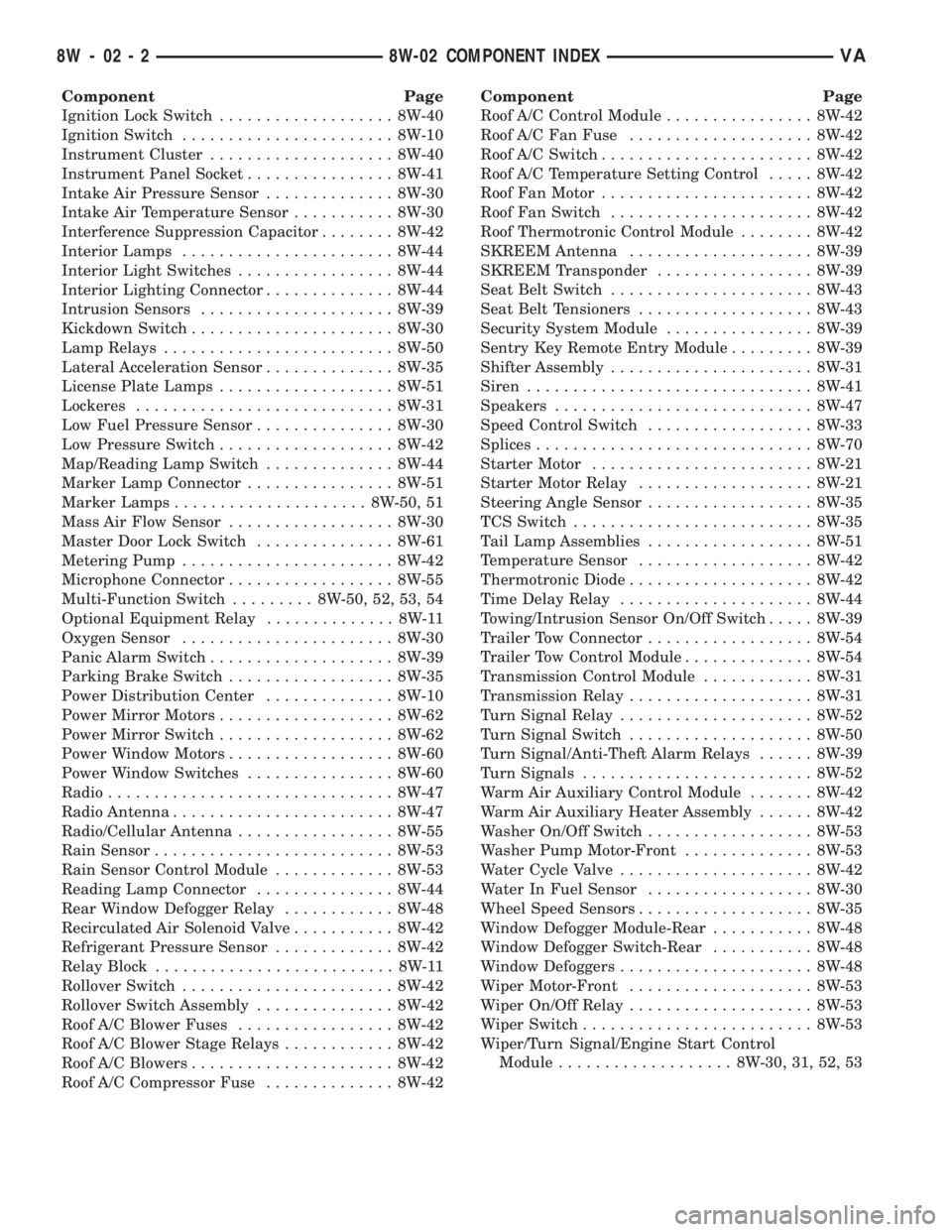
Component Page
Ignition Lock Switch................... 8W-40
Ignition Switch....................... 8W-10
Instrument Cluster.................... 8W-40
Instrument Panel Socket................ 8W-41
Intake Air Pressure Sensor.............. 8W-30
Intake Air Temperature Sensor........... 8W-30
Interference Suppression Capacitor........ 8W-42
Interior Lamps....................... 8W-44
Interior Light Switches................. 8W-44
Interior Lighting Connector.............. 8W-44
Intrusion Sensors..................... 8W-39
Kickdown Switch...................... 8W-30
Lamp Relays......................... 8W-50
Lateral Acceleration Sensor.............. 8W-35
License Plate Lamps................... 8W-51
Lockeres............................ 8W-31
Low Fuel Pressure Sensor............... 8W-30
Low Pressure Switch................... 8W-42
Map/Reading Lamp Switch.............. 8W-44
Marker Lamp Connector................ 8W-51
Marker Lamps..................... 8W-50, 51
Mass Air Flow Sensor.................. 8W-30
Master Door Lock Switch............... 8W-61
Metering Pump....................... 8W-42
Microphone Connector.................. 8W-55
Multi-Function Switch......... 8W-50, 52, 53, 54
Optional Equipment Relay.............. 8W-11
Oxygen Sensor....................... 8W-30
Panic Alarm Switch.................... 8W-39
Parking Brake Switch.................. 8W-35
Power Distribution Center.............. 8W-10
Power Mirror Motors................... 8W-62
Power Mirror Switch................... 8W-62
Power Window Motors.................. 8W-60
Power Window Switches................ 8W-60
Radio............................... 8W-47
Radio Antenna........................ 8W-47
Radio/Cellular Antenna................. 8W-55
Rain Sensor.......................... 8W-53
Rain Sensor Control Module............. 8W-53
Reading Lamp Connector............... 8W-44
Rear Window Defogger Relay............ 8W-48
Recirculated Air Solenoid Valve........... 8W-42
Refrigerant Pressure Sensor............. 8W-42
Relay Block.......................... 8W-11
Rollover Switch....................... 8W-42
Rollover Switch Assembly............... 8W-42
Roof A/C Blower Fuses................. 8W-42
Roof A/C Blower Stage Relays............ 8W-42
Roof A/C Blowers...................... 8W-42
Roof A/C Compressor Fuse.............. 8W-42Component Page
Roof A/C Control Module................ 8W-42
Roof A/C Fan Fuse.................... 8W-42
Roof A/C Switch....................... 8W-42
Roof A/C Temperature Setting Control..... 8W-42
Roof Fan Motor....................... 8W-42
Roof Fan Switch...................... 8W-42
Roof Thermotronic Control Module........ 8W-42
SKREEM Antenna.................... 8W-39
SKREEM Transponder................. 8W-39
Seat Belt Switch...................... 8W-43
Seat Belt Tensioners................... 8W-43
Security System Module................ 8W-39
Sentry Key Remote Entry Module......... 8W-39
Shifter Assembly...................... 8W-31
Siren............................... 8W-41
Speakers............................ 8W-47
Speed Control Switch.................. 8W-33
Splices.............................. 8W-70
Starter Motor........................ 8W-21
Starter Motor Relay................... 8W-21
Steering Angle Sensor.................. 8W-35
TCS Switch.......................... 8W-35
Tail Lamp Assemblies.................. 8W-51
Temperature Sensor................... 8W-42
Thermotronic Diode.................... 8W-42
Time Delay Relay..................... 8W-44
Towing/Intrusion Sensor On/Off Switch..... 8W-39
Trailer Tow Connector.................. 8W-54
Trailer Tow Control Module.............. 8W-54
Transmission Control Module............ 8W-31
Transmission Relay.................... 8W-31
Turn Signal Relay..................... 8W-52
Turn Signal Switch.................... 8W-50
Turn Signal/Anti-Theft Alarm Relays...... 8W-39
Turn Signals......................... 8W-52
Warm Air Auxiliary Control Module....... 8W-42
Warm Air Auxiliary Heater Assembly...... 8W-42
Washer On/Off Switch.................. 8W-53
Washer Pump Motor-Front.............. 8W-53
Water Cycle Valve..................... 8W-42
Water In Fuel Sensor.................. 8W-30
Wheel Speed Sensors................... 8W-35
Window Defogger Module-Rear........... 8W-48
Window Defogger Switch-Rear........... 8W-48
Window Defoggers..................... 8W-48
Wiper Motor-Front.................... 8W-53
Wiper On/Off Relay.................... 8W-53
Wiper Switch......................... 8W-53
Wiper/Turn Signal/Engine Start Control
Module................... 8W-30, 31, 52, 53
8W - 02 - 2 8W-02 COMPONENT INDEXVA