2006 MERCEDES-BENZ SPRINTER head gasket
[x] Cancel search: head gasketPage 829 of 2305
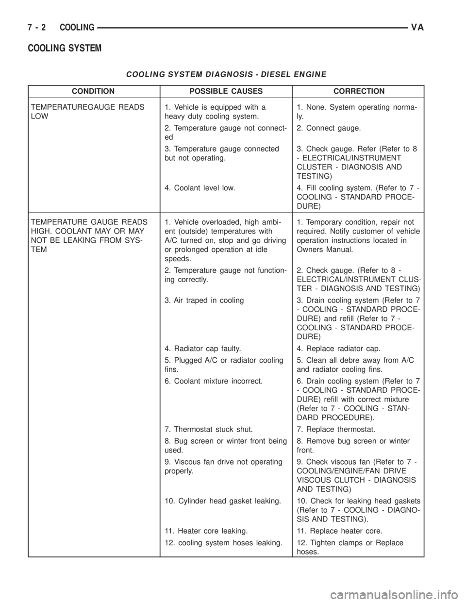
COOLING SYSTEM
COOLING SYSTEM DIAGNOSIS - DIESEL ENGINE
CONDITION POSSIBLE CAUSES CORRECTION
TEMPERATUREGAUGE READS
LOW1. Vehicle is equipped with a
heavy duty cooling system.1. None. System operating norma-
ly.
2. Temperature gauge not connect-
ed2. Connect gauge.
3. Temperature gauge connected
but not operating.3. Check gauge. Refer (Refer to 8
- ELECTRICAL/INSTRUMENT
CLUSTER - DIAGNOSIS AND
TESTING)
4. Coolant level low. 4. Fill cooling system. (Refer to 7 -
COOLING - STANDARD PROCE-
DURE)
TEMPERATURE GAUGE READS
HIGH. COOLANT MAY OR MAY
NOT BE LEAKING FROM SYS-
TEM1. Vehicle overloaded, high ambi-
ent (outside) temperatures with
A/C turned on, stop and go driving
or prolonged operation at idle
speeds.1. Temporary condition, repair not
required. Notify customer of vehicle
operation instructions located in
Owners Manual.
2. Temperature gauge not function-
ing correctly.2. Check gauge. (Refer to 8 -
ELECTRICAL/INSTRUMENT CLUS-
TER - DIAGNOSIS AND TESTING)
3. Air traped in cooling 3. Drain cooling system (Refer to 7
- COOLING - STANDARD PROCE-
DURE) and refill (Refer to 7 -
COOLING - STANDARD PROCE-
DURE)
4. Radiator cap faulty. 4. Replace radiator cap.
5. Plugged A/C or radiator cooling
fins.5. Clean all debre away from A/C
and radiator cooling fins.
6. Coolant mixture incorrect. 6. Drain cooling system (Refer to 7
- COOLING - STANDARD PROCE-
DURE) refill with correct mixture
(Refer to 7 - COOLING - STAN-
DARD PROCEDURE).
7. Thermostat stuck shut. 7. Replace thermostat.
8. Bug screen or winter front being
used.8. Remove bug screen or winter
front.
9. Viscous fan drive not operating
properly.9. Check viscous fan (Refer to 7 -
COOLING/ENGINE/FAN DRIVE
VISCOUS CLUTCH - DIAGNOSIS
AND TESTING)
10. Cylinder head gasket leaking. 10. Check for leaking head gaskets
(Refer to 7 - COOLING - DIAGNO-
SIS AND TESTING).
11. Heater core leaking. 11. Replace heater core.
12. cooling system hoses leaking. 12. Tighten clamps or Replace
hoses.
7 - 2 COOLINGVA
Page 838 of 2305

Operate tester pump to apply 103.4 kPa (15 psi)
pressure to system. If hoses enlarge excessively or
bulges while testing, replace as necessary. Observe
gauge pointer and determine condition of cooling sys-
tem according to following criteria:
Holds Steady:If pointer remains steady for two
minutes, serious coolant leaks are not present in sys-
tem. However, there could be an internal leak that
does not appear with normal system test pressure. If
it is certain that coolant is being lost and leaks can-
not be detected, inspect for interior leakage or per-
form Internal Leakage Test.
Drops Slowly:Indicates a small leak or seepage
is occurring. Examine all connections for seepage or
slight leakage with a flashlight. Inspect radiator,
hoses, gasket edges and heater. Seal small leak holes
with a Sealer Lubricant (or equivalent). Repair leak
holes and inspect system again with pressure
applied.
Drops Quickly:Indicates that serious leakage is
occurring. Examine system for external leakage. If
leaks are not visible, inspect for internal leakage.
Large radiator leak holes should be repaired by a
reputable radiator repair shop.
INTERNAL LEAKAGE INSPECTION
Remove engine oil pan drain plug and drain a
small amount of engine oil. If coolant is present in
the pan, it will drain first because it is heavier than
oil. An alternative method is to operate engine for a
short period to churn the oil. After this is done,
remove engine dipstick and inspect for water glob-ules. Also inspect transmission dipstick for water
globules and transmission fluid cooler for leakage.
WARNING: WITH RADIATOR PRESSURE TESTER
TOOL INSTALLED ON RADIATOR, DO NOT ALLOW
PRESSURE TO EXCEED 110 KPA (20 PSI). PRES-
SURE WILL BUILD UP QUICKLY IF A COMBUSTION
LEAK IS PRESENT. TO RELEASE PRESSURE,
ROCK TESTER FROM SIDE TO SIDE. WHEN
REMOVING TESTER, DO NOT TURN TESTER MORE
THAN 1/2 TURN IF SYSTEM IS UNDER PRESSURE.
Operate engine without pressure cap on coolant
container until thermostat opens. Attach a Pressure
Tester to container. If pressure builds up quickly it
indicates a combustion leak exists. This is usually
the result of a cylinder head gasket leak or crack in
engine. Repair as necessary.
If there is not an immediate pressure increase,
pump the Pressure Tester. Do this until indicated
pressure is within system range of 110 kPa (16 psi).
Fluctuation of gauge pointer indicates compression or
combustion leakage into cooling system.
Because the vehicle is equipped with a catalytic
converter,do notremove spark plug cables or short
out cylinders to isolate compression leak.
If the needle on dial of pressure tester does not
fluctuate, race engine a few times to check for an
abnormal amount of coolant or steam. This would be
emitting from exhaust pipe. Coolant or steam from
exhaust pipe may indicate a faulty cylinder head gas-
ket, cracked engine cylinder block or cylinder head.
A convenient check for exhaust gas leakage into
cooling system is provided by a commercially avail-
able Block Leak Check tool. Follow manufacturers
instructions when using this product.
COMBUSTION LEAKAGE TEST - WITHOUT PRES-
SURE TESTER
DO NOT WASTE reusable coolant. If solution is
clean, drain coolant into a clean and suitably marked
container for reuse.
WARNING: Do not remove cylinder block drain
plugs or loosen radiator drain with system hot and
under pressure. serious burns from coolant can
occur.
Drain sufficient coolant to allow thermostat
removal.
Remove accessory drive belt.
Add coolant to pressure container to bring level to
within 6.3 mm (1/4 in) of top of thermostat housing.
CAUTION: Avoid overheating. Do not operate
engine for an excessive period of time. Open drain-
cock immediately after test to eliminate boil over.
Fig. 2 PRESSURE TESTING
1 - PRESSURE RESERVOIR CAP
2 - PRESSURE RESERVOIR
3 - PRESSURE TESTER
VAENGINE 7 - 11
Page 1579 of 2305
NOTE: If the retaining lock is installed, remove it,
rotate engine and install lock once again.
(2) Carry out test of other cylinders in the firing
order of engine.
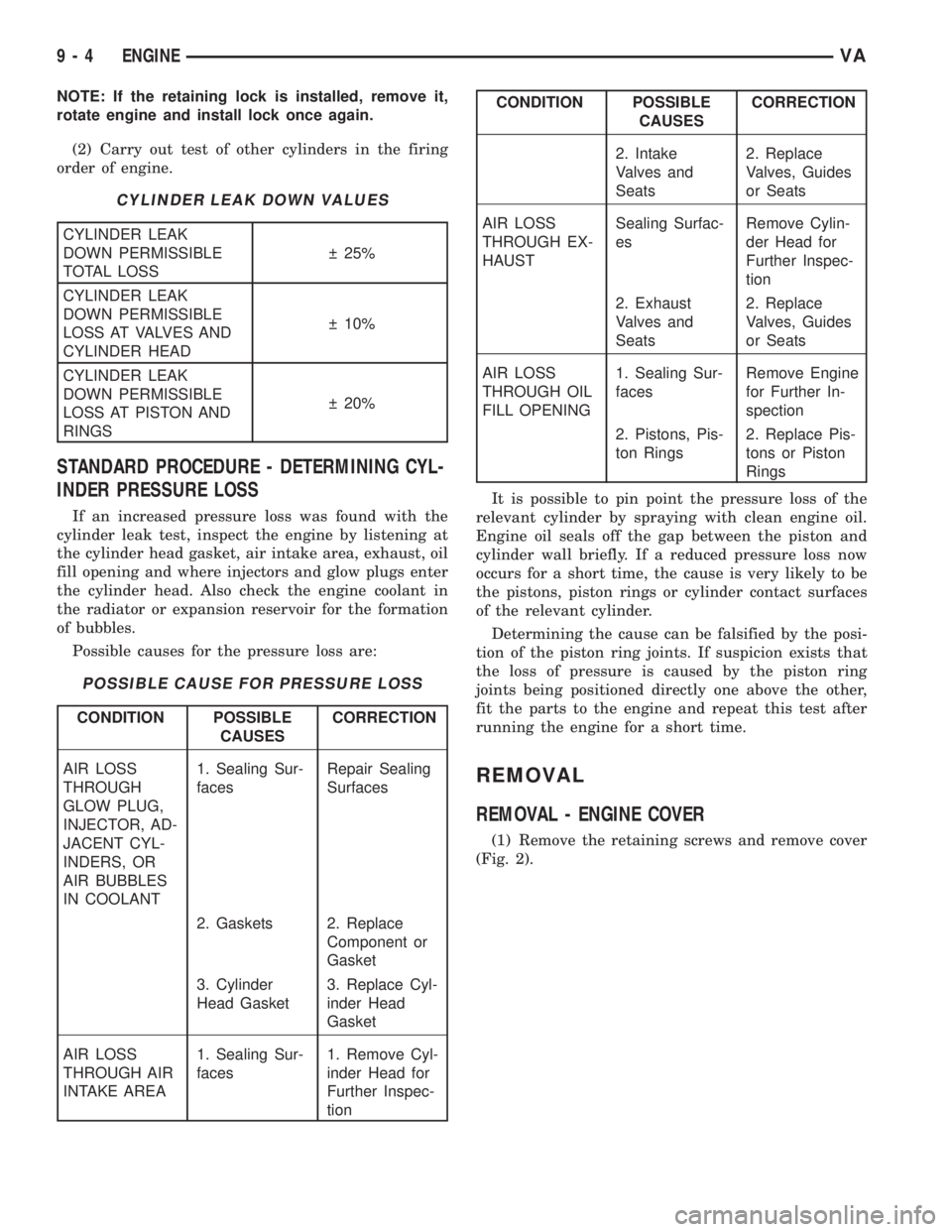
CYLINDER LEAK DOWN VALUES
CYLINDER LEAK
DOWN PERMISSIBLE
TOTAL LOSS 25%
CYLINDER LEAK
DOWN PERMISSIBLE
LOSS AT VALVES AND
CYLINDER HEAD 10%
CYLINDER LEAK
DOWN PERMISSIBLE
LOSS AT PISTON AND
RINGS 20%
STANDARD PROCEDURE - DETERMINING CYL-
INDER PRESSURE LOSS
If an increased pressure loss was found with the
cylinder leak test, inspect the engine by listening at
the cylinder head gasket, air intake area, exhaust, oil
fill opening and where injectors and glow plugs enter
the cylinder head. Also check the engine coolant in
the radiator or expansion reservoir for the formation
of bubbles.
Possible causes for the pressure loss are:
POSSIBLE CAUSE FOR PRESSURE LOSS
CONDITION POSSIBLE
CAUSESCORRECTION
AIR LOSS
THROUGH
GLOW PLUG,
INJECTOR, AD-
JACENT CYL-
INDERS, OR
AIR BUBBLES
IN COOLANT1. Sealing Sur-
facesRepair Sealing
Surfaces
2. Gaskets 2. Replace
Component or
Gasket
3. Cylinder
Head Gasket3. Replace Cyl-
inder Head
Gasket
AIR LOSS
THROUGH AIR
INTAKE AREA1. Sealing Sur-
faces1. Remove Cyl-
inder Head for
Further Inspec-
tion
CONDITION POSSIBLE
CAUSESCORRECTION
2. Intake
Valves and
Seats2. Replace
Valves, Guides
or Seats
AIR LOSS
THROUGH EX-
HAUSTSealing Surfac-
esRemove Cylin-
der Head for
Further Inspec-
tion
2. Exhaust
Valves and
Seats2. Replace
Valves, Guides
or Seats
AIR LOSS
THROUGH OIL
FILL OPENING1. Sealing Sur-
facesRemove Engine
for Further In-
spection
2. Pistons, Pis-
ton Rings2. Replace Pis-
tons or Piston
Rings
It is possible to pin point the pressure loss of the
relevant cylinder by spraying with clean engine oil.
Engine oil seals off the gap between the piston and
cylinder wall briefly. If a reduced pressure loss now
occurs for a short time, the cause is very likely to be
the pistons, piston rings or cylinder contact surfaces
of the relevant cylinder.
Determining the cause can be falsified by the posi-
tion of the piston ring joints. If suspicion exists that
the loss of pressure is caused by the piston ring
joints being positioned directly one above the other,
fit the parts to the engine and repeat this test after
running the engine for a short time.
REMOVAL
REMOVAL - ENGINE COVER
(1) Remove the retaining screws and remove cover
(Fig. 2).
9 - 4 ENGINEVA
Page 1597 of 2305
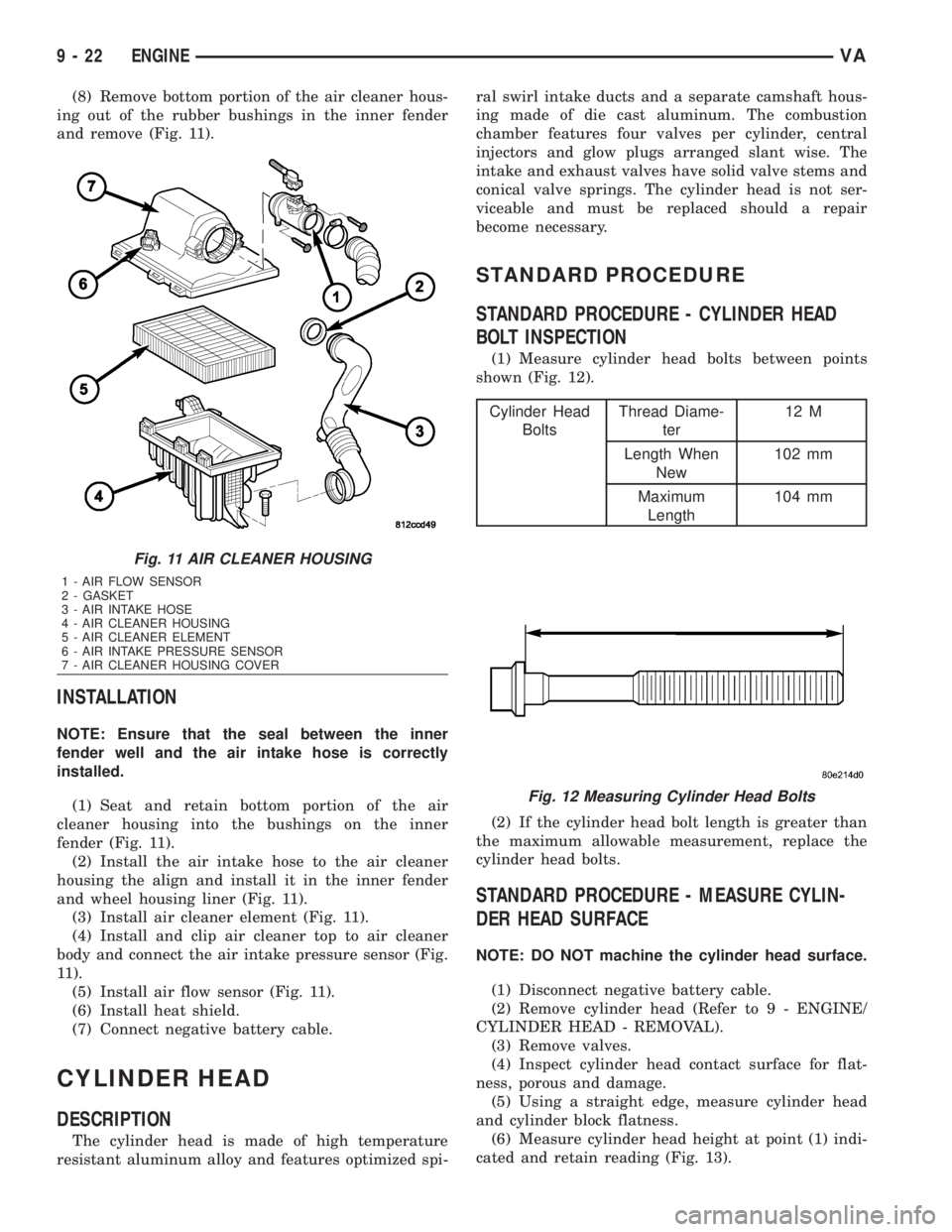
(8) Remove bottom portion of the air cleaner hous-
ing out of the rubber bushings in the inner fender
and remove (Fig. 11).
INSTALLATION
NOTE: Ensure that the seal between the inner
fender well and the air intake hose is correctly
installed.
(1) Seat and retain bottom portion of the air
cleaner housing into the bushings on the inner
fender (Fig. 11).
(2) Install the air intake hose to the air cleaner
housing the align and install it in the inner fender
and wheel housing liner (Fig. 11).
(3) Install air cleaner element (Fig. 11).
(4) Install and clip air cleaner top to air cleaner
body and connect the air intake pressure sensor (Fig.
11).
(5) Install air flow sensor (Fig. 11).
(6) Install heat shield.
(7) Connect negative battery cable.
CYLINDER HEAD
DESCRIPTION
The cylinder head is made of high temperature
resistant aluminum alloy and features optimized spi-ral swirl intake ducts and a separate camshaft hous-
ing made of die cast aluminum. The combustion
chamber features four valves per cylinder, central
injectors and glow plugs arranged slant wise. The
intake and exhaust valves have solid valve stems and
conical valve springs. The cylinder head is not ser-
viceable and must be replaced should a repair
become necessary.
STANDARD PROCEDURE
STANDARD PROCEDURE - CYLINDER HEAD
BOLT INSPECTION
(1) Measure cylinder head bolts between points
shown (Fig. 12).
Cylinder Head
BoltsThread Diame-
ter12 M
Length When
New102 mm
Maximum
Length104 mm
(2) If the cylinder head bolt length is greater than
the maximum allowable measurement, replace the
cylinder head bolts.
STANDARD PROCEDURE - MEASURE CYLIN-
DER HEAD SURFACE
NOTE: DO NOT machine the cylinder head surface.
(1) Disconnect negative battery cable.
(2) Remove cylinder head (Refer to 9 - ENGINE/
CYLINDER HEAD - REMOVAL).
(3) Remove valves.
(4) Inspect cylinder head contact surface for flat-
ness, porous and damage.
(5) Using a straight edge, measure cylinder head
and cylinder block flatness.
(6) Measure cylinder head height at point (1) indi-
cated and retain reading (Fig. 13).
Fig. 11 AIR CLEANER HOUSING
1 - AIR FLOW SENSOR
2 - GASKET
3 - AIR INTAKE HOSE
4 - AIR CLEANER HOUSING
5 - AIR CLEANER ELEMENT
6 - AIR INTAKE PRESSURE SENSOR
7 - AIR CLEANER HOUSING COVER
Fig. 12 Measuring Cylinder Head Bolts
9 - 22 ENGINEVA
Page 1600 of 2305
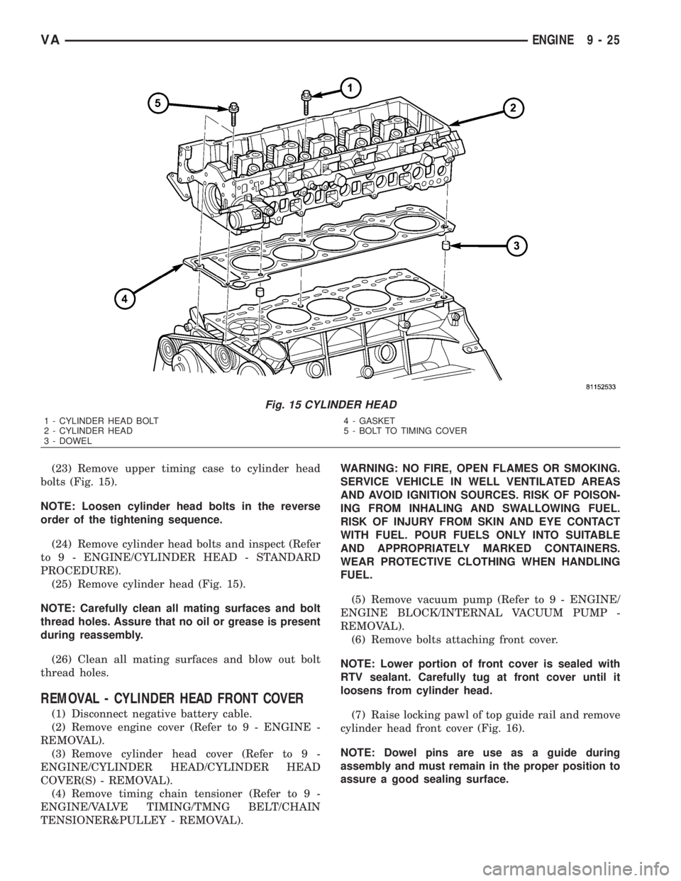
(23) Remove upper timing case to cylinder head
bolts (Fig. 15).
NOTE: Loosen cylinder head bolts in the reverse
order of the tightening sequence.
(24) Remove cylinder head bolts and inspect (Refer
to 9 - ENGINE/CYLINDER HEAD - STANDARD
PROCEDURE).
(25) Remove cylinder head (Fig. 15).
NOTE: Carefully clean all mating surfaces and bolt
thread holes. Assure that no oil or grease is present
during reassembly.
(26) Clean all mating surfaces and blow out bolt
thread holes.
REMOVAL - CYLINDER HEAD FRONT COVER
(1) Disconnect negative battery cable.
(2) Remove engine cover (Refer to 9 - ENGINE -
REMOVAL).
(3) Remove cylinder head cover (Refer to 9 -
ENGINE/CYLINDER HEAD/CYLINDER HEAD
COVER(S) - REMOVAL).
(4) Remove timing chain tensioner (Refer to 9 -
ENGINE/VALVE TIMING/TMNG BELT/CHAIN
TENSIONER&PULLEY - REMOVAL).WARNING: NO FIRE, OPEN FLAMES OR SMOKING.
SERVICE VEHICLE IN WELL VENTILATED AREAS
AND AVOID IGNITION SOURCES. RISK OF POISON-
ING FROM INHALING AND SWALLOWING FUEL.
RISK OF INJURY FROM SKIN AND EYE CONTACT
WITH FUEL. POUR FUELS ONLY INTO SUITABLE
AND APPROPRIATELY MARKED CONTAINERS.
WEAR PROTECTIVE CLOTHING WHEN HANDLING
FUEL.
(5) Remove vacuum pump (Refer to 9 - ENGINE/
ENGINE BLOCK/INTERNAL VACUUM PUMP -
REMOVAL).
(6) Remove bolts attaching front cover.
NOTE: Lower portion of front cover is sealed with
RTV sealant. Carefully tug at front cover until it
loosens from cylinder head.
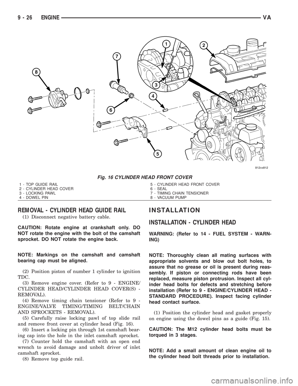
(7) Raise locking pawl of top guide rail and remove
cylinder head front cover (Fig. 16).
NOTE: Dowel pins are use as a guide during
assembly and must remain in the proper position to
assure a good sealing surface.
Fig. 15 CYLINDER HEAD
1 - CYLINDER HEAD BOLT
2 - CYLINDER HEAD
3 - DOWEL4 - GASKET
5 - BOLT TO TIMING COVER
VAENGINE 9 - 25
Page 1601 of 2305
REMOVAL - CYLINDER HEAD GUIDE RAIL
(1) Disconnect negative battery cable.
CAUTION: Rotate engine at crankshaft only. DO
NOT rotate the engine with the bolt of the camshaft
sprocket. DO NOT rotate the engine back.
NOTE: Markings on the camshaft and camshaft
bearing cap must be aligned.
(2) Position piston of number 1 cylinder to ignition
TDC.
(3) Remove engine cover. (Refer to 9 - ENGINE/
CYLINDER HEAD/CYLINDER HEAD COVER(S) -
REMOVAL).
(4) Remove timing chain tensioner (Refer to 9 -
ENGINE/VALVE TIMING/TIMING BELT/CHAIN
AND SPROCKETS - REMOVAL).
(5) Carefully raise locking pawl of top slide rail
and remove front cover at cylinder head (Fig. 16).
(6) Insert a locking pin through 1st camshaft bear-
ing cap into the hole in the inlet camshaft sprocket.
(7) Counter hold the camshaft with an open end
wrench to avoid damage and unbolt driver of inlet
camshaft sprocket.
(8) Remove top guide rail.
INSTALLATION
INSTALLATION - CYLINDER HEAD
WARNING: (Refer to 14 - FUEL SYSTEM - WARN-
ING)
NOTE: Thoroughly clean all mating surfaces with
appropriate solvents and blow out bolt holes, to
assure that no grease or oil is present during reas-
sembly. If piston or connecting rods have been
replaced, measure piston protrusion. Inspect all cyl-
inder head bolts for defects and stretching before
installation (Refer to 9 - ENGINE/CYLINDER HEAD -
STANDARD PROCEDURE). Inspect facing cylinder
head contact surface.
(1) Position the cylinder head and gasket properly
on engine using the dowel pins as a guide (Fig. 15).
CAUTION: The M12 cylinder head bolts must be
torqued in 3 stages.
NOTE: Add a small amount of clean engine oil to
the cylinder head bolt threads prior to installation.
Fig. 16 CYLINDER HEAD FRONT COVER
1 - TOP GUIDE RAIL
2 - CYLINDER HEAD COVER
3 - LOCKING PAWL
4 - DOWEL PIN5 - CYLINDER HEAD FRONT COVER
6 - SEAL
7 - TIMING CHAIN TENSIONER
8 - VACUUM PUMP
9 - 26 ENGINEVA
Page 1603 of 2305

INSTALLATION - CYLINDER HEAD FRONT
COVER
NOTE: Thoroughly clean all mating surfaces with
appropriate solvents to assure that no grease or oil
is present during reassembly.
NOTE: Dowel pins are used as a guide during
assembly and must remain in the proper position to
assure a good sealing surface.
(1) Apply sealant to the marked surfaces with a
bead thickness of 1.5 0.5 mm (Fig. 18).
NOTE: Install front cover of cylinder head within 10
minutes after applying sealant. Do not spread seal-
ing bead.
(2) Raise locking pawl of top guide rail and guide
front cover onto guide pins.
(3) Install bolts attaching front cover (Fig. 16)
Tighten bolts to 14N´m (124 lbs. in.).
WARNING: NO FIRE, OPEN FLAMES OR SMOKING.
REMOVE SOURCES OF IGNITION FROM THE AREA.
WEAR PROTECTIVE CLOTHING WHEN HANDLING
FUEL. RISK OF POISONING FROM INHALING AND
SWALLOWING FUEL. RISK OF INJURY FROM SKIN
AND EYE CONTACT WITH FUEL. POUR FUELS
ONLY INTO SUITABLE AND APPROPRIATELY
MARKED CONTAINERS.
(4) Install vacuum pump (Refer to 9 - ENGINE/
ENGINE BLOCK/INTERNAL VACUUM PUMP -
INSTALLATION).NOTE: Timing chain tensioner must be installed
with a new gasket.
(5) Install timing chain tensioner (Refer to 9 -
ENGINE/VALVE TIMING/TIMING BELT/CHAIN
AND SPROCKETS - INSTALLATION).
(6) Connect negative battery cable.
WARNING: USE EXTREME CAUTION WHEN THE
ENGINE IS OPERATING. DO NOT STAND IN A
DIRECT LINE WITH THE FAN. DO NOT PUT YOUR
HANDS NEAR THE PULLEYS, BELTS OR FAN. DO
NOT WEAR LOOSE CLOTHES.
(7) Start the engine and inspect for leaks. Care
must be taken to observe the fuel system warning
(Refer to 14 - FUEL SYSTEM - WARNING)
INSTALLATION - CYLINDER HEAD GUIDE RAIL
(1) Carefully position the top guide rail onto the
guide pins.
(2) Counter hold the camshaft with an open end
wrench and install driver of inlet camshaft sprocket.
Tight bolt to 50N´m (37 lbs. ft.).
(3) Remove camshaft sprocket locking pin.
(4) Carefully raise locking pawl of top guide rail
and install front cover at cylinder head (Fig. 16).
(5) Install timing chain tensioner with new gasket
(Refer to 9 - ENGINE/VALVE TIMING/TIMING
BELT/CHAIN AND SPROCKETS - INSTALLA-
TION).
(6) Install engine cover (Refer to 9 - ENGINE/
CYLINDER HEAD/CYLINDER HEAD COVER(S) -
INSTALLATION).
(7) Reconnect negative battery cable.
WARNING: US EXTREME CAUTION WHEN THE
ENGINE IS OPERATING. DO NOT STAND IN A
DIRECT LINE WITH THE FAN. DO NOT PUT YOUR
HANDS NEAR THE PULLEYS, BELTS OR FAN. DO
NOT WEAR LOOSE CLOTHES.
(8) Start engine and inspect for leaks.
CAMSHAFT(S)
STANDARD PROCEDURE
STANDARD PROCEDURE - CHECKING CAM-
SHAFT POSITION
(1) Disconnect negative battery cable.
(2) Remove engine cover (Refer to 9 - ENGINE
COVER - REMOVAL).
WARNING: (Refer to 14 - FUEL SYSTEM - WARN-
ING)
Fig. 18 CYLINDER HEAD COVER SEALING
SURFACE
1 - CYLINDER HEAD FRONT COVER
2 - SEALANT BEAD
9 - 28 ENGINEVA
Page 1609 of 2305
INSTALLATION
NOTE: Do Not tighten the cylinder head cover first.
The fuel injectors are aligned by way of the cylinder
head cover.
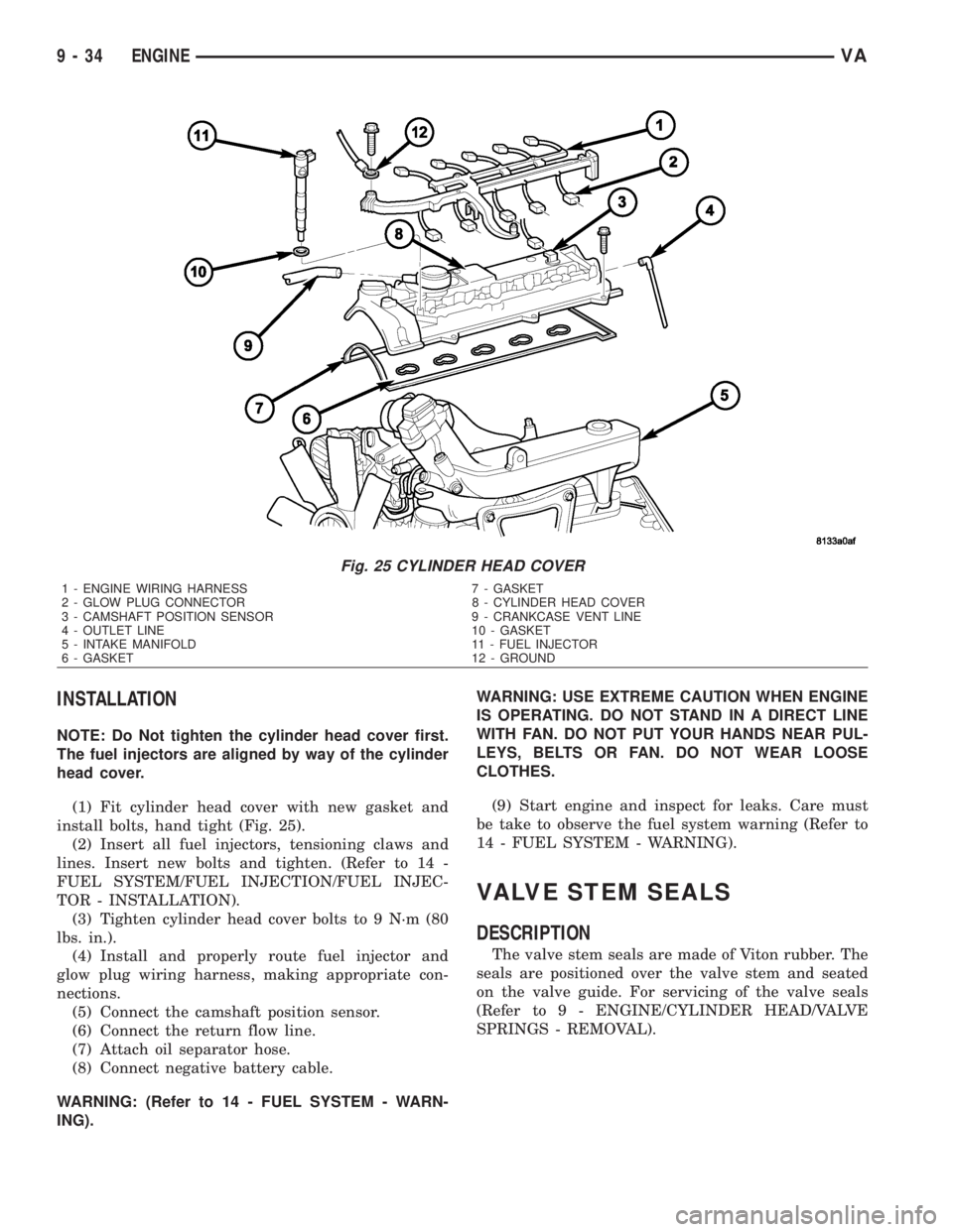
(1) Fit cylinder head cover with new gasket and
install bolts, hand tight (Fig. 25).
(2) Insert all fuel injectors, tensioning claws and
lines. Insert new bolts and tighten. (Refer to 14 -
FUEL SYSTEM/FUEL INJECTION/FUEL INJEC-
TOR - INSTALLATION).
(3) Tighten cylinder head cover bolts to 9 N´m (80
lbs. in.).
(4) Install and properly route fuel injector and
glow plug wiring harness, making appropriate con-
nections.
(5) Connect the camshaft position sensor.
(6) Connect the return flow line.
(7) Attach oil separator hose.
(8) Connect negative battery cable.
WARNING: (Refer to 14 - FUEL SYSTEM - WARN-
ING).WARNING: USE EXTREME CAUTION WHEN ENGINE
IS OPERATING. DO NOT STAND IN A DIRECT LINE
WITH FAN. DO NOT PUT YOUR HANDS NEAR PUL-
LEYS, BELTS OR FAN. DO NOT WEAR LOOSE
CLOTHES.
(9) Start engine and inspect for leaks. Care must
be take to observe the fuel system warning (Refer to
14 - FUEL SYSTEM - WARNING).
VALVE STEM SEALS
DESCRIPTION
The valve stem seals are made of Viton rubber. The
seals are positioned over the valve stem and seated
on the valve guide. For servicing of the valve seals
(Refer to 9 - ENGINE/CYLINDER HEAD/VALVE
SPRINGS - REMOVAL).
Fig. 25 CYLINDER HEAD COVER
1 - ENGINE WIRING HARNESS 7 - GASKET
2 - GLOW PLUG CONNECTOR 8 - CYLINDER HEAD COVER
3 - CAMSHAFT POSITION SENSOR 9 - CRANKCASE VENT LINE
4 - OUTLET LINE 10 - GASKET
5 - INTAKE MANIFOLD 11 - FUEL INJECTOR
6 - GASKET 12 - GROUND
9 - 34 ENGINEVA