2006 MERCEDES-BENZ SPRINTER ground
[x] Cancel search: groundPage 7 of 2305

TABLE OF CONTENTS - Continued
5.0 REQUIRED TOOLS AND EQUIPMENT.....................................13
6.0 GLOSSARY OF TERMS..................................................13
7.0 DIAGNOSTIC INFORMATION AND PROCEDURES...........................15
AIRBAG
AIRBAG WARNING INDICATOR - DRIVER HIGH.............................16
AIRBAG WARNING INDICATOR - DRIVER LOW..............................19
DRIVER SEAT BELT TENSIONER - INCORRECT FEEDBACK..................22
DRIVER SQUIB 1 - INCORRECT FEEDBACK................................22
INTERNAL 1...........................................................22
INTERNAL 2...........................................................22
INTERNAL 3...........................................................22
PASSENGER SEAT BELT TENSIONER - INCORRECT FEEDBACK..............22
PASSENGER SQUIB 1 - INCORRECT FEEDBACK............................22
STORED ENERGY FIRING 1..............................................22
STORED ENERGY FIRING 2..............................................22
DRIVER SEAT BELT TENSIONER CIRCUIT OPEN............................24
DRIVER SEAT BELT TENSIONER CIRCUIT SHORT..........................26
DRIVER SEAT BELT TENSIONER SHORT TO BATTERY.......................28
DRIVER SEAT BELT TENSIONER SHORT TO GROUND.......................31
DRIVER SQUIB 1 CIRCUIT OPEN.........................................33
DRIVER SQUIB 1 CIRCUIT SHORT........................................36
DRIVER SQUIB 1 SHORT TO BATTERY....................................39
DRIVER SQUIB 1 SHORT TO GROUND....................................42
LOSS OF IGNITION RUN - START.........................................45
PASSENGER SEAT BELT TENSIONER CIRCUIT OPEN.......................47
PASSENGER SEAT BELT TENSIONER CIRCUIT SHORT......................49
PASSENGER SEAT BELT TENSIONER SHORT TO BATTERY..................51
PASSENGER SEAT BELT TENSIONER SHORT TO GROUND..................54
PASSENGER SQUIB 1 CIRCUIT OPEN.....................................56
PASSENGER SQUIB 1 CIRCUIT SHORT....................................59
PASSENGER SQUIB 1 SHORT TO BATTERY................................62
PASSENGER SQUIB 1 SHORT TO GROUND................................65
*AIRBAG WARNING INDICATOR FLASHING.................................68
CABIN HEATER
A. HEATER PRE-TEST...................................................69
CIRC PUMP CONTROL OPEN............................................72
CIRC PUMP CONTROL SHORTED.........................................74
COMBUST FAN SHORTED...............................................76
COMBUST FAN SPEED INCORRECT......................................76
COMBUSTION FAN OPEN................................................76
CONTROL UNIT FAULTY.................................................77
DOSING PUMP OPEN...................................................78
DOSING PUMP SHORTED...............................................81
FAN STAGE 1 RELAY CONTROL OPEN....................................83
FAN STAGE 1 RELAY CONTROL SHORTED.................................85
FLAME DETECT PRIOR TO COMBUST.....................................87
FLAME OUT...........................................................88
NO START.............................................................88
FLAME SENSOR OPEN..................................................91
ii
Page 9 of 2305

TABLE OF CONTENTS - Continued
A/C COMPRESSOR CONTROL SHORTED LOW (ACTIVE)....................132
AIR OUTLET TEMP SENSOR HIGH OR OPEN (ACTIVE).....................134
AIR OUTLET TEMP SENSOR SHORTED LOW (ACTIVE).....................136
ATC FUNCTION TEST COOL FAILURE....................................138
ATC FUNCTION TEST FAILURE..........................................138
ATC FUNCTION TEST HEAT FAILURE.....................................138
AUX FAN RELAY CONTROL HIGH OR OPEN (ACTIVE)......................140
AUX FAN RELAY CONTROL SHORTED LOW (ACTIVE)......................142
BLOWER STAGE 1 HIGH OR OPEN (ACTIVE)..............................144
BLOWER STAGE 1 SHORTED LOW (ACTIVE)..............................146
CABIN HEATER CONTROL HIGH OR OPEN (ACTIVE).......................148
CABIN HEATER CONTROL SHORTED LOW (ACTIVE).......................150
CIRC PUMP CONTROL HIGH OR OPEN (ACTIVE)..........................152
CIRC PUMP CONTROL SHORTED LOW (ACTIVE)..........................154
EVAP TEMP SENSOR HIGH OR OPEN (ACTIVE)...........................156
EVAP TEMP SENSOR SHORTED LOW (ACTIVE)...........................158
NO COMMUNICATION BUS (ACTIVE).....................................160
NO COMMUNICATION WITH ECM (ACTIVE)...............................163
NO COMMUNICATION WITH IC (ACTIVE)..................................165
RECIRC AIR SOLENOID CONTROL HIGH OR OPEN (ACTIVE)................167
RECIRC AIR SOLENOID CONTROL SHORTED LOW (ACTIVE)................169
REFRIG PRESS SENSOR HIGH OR OPEN (ACTIVE)........................171
REFRIG PRESS SENSOR SHORTED LOW (ACTIVE)........................173
WATER CYCLE VALVE CONTROL HIGH OR OPEN (ACTIVE).................175
WATER CYCLE VALVE CONTROL SHORTED LOW (ACTIVE).................177
INSTRUMENT CLUSTER
AMBIENT TEMP SENSOR OPEN/SHORT TO BATTERY......................179
AMBIENT TEMP SENSOR SHORT TO GROUND............................181
FUEL LEVEL SENSOR OPEN/SHORT TO BATTERY.........................182
FUEL LEVEL SENSOR SHORT TO GROUND...............................184
INSTRUMENT CLUSTER INTERNAL FAILURE B1043........................185
INSTRUMENT CLUSTER INTERNAL FAILURE B1053........................186
INSTRUMENT CLUSTER OVERVOLTAGE..................................187
NO CAN COMMUNICATION WITH ABS....................................188
NO CAN COMMUNICATION WITH ECM...................................190
NO CAN COMMUNICATION WITH TCM....................................192
PREGLOW INDICATOR LAMP FAILURE...................................194
SRS INDICATOR LAMP FAILURE.........................................195
POWER DOOR LOCKS/RKE
DRIVER DOOR AJAR INDICATOR DRIVER CIRCUIT SHORT TO GROUND......196
PASSENGER DOOR AJAR INDICATOR DRIVER CIRCUIT SHORT TO GROUND .198
REPLACE CONTROL MODULE..........................................200
RKE INTERFACE CIRCUIT SHORT TO GROUND - CTM......................201
RKE INTERFACE CIRCUIT SHORT TO GROUND - SKREEM..................203
RKE INTERFACE CIRCUIT SHORT TO VOLTAGE - CTM.....................205
RKE INTERFACE CIRCUIT SHORT TO VOLTAGE - SKREEM..................206
THE ACM HAS UNLOCKED THE DOORS..................................208
UNKNOWN TROUBLE CODE UNKNOWN DTC TYPE 2......................209
*RKE INOPERATIVE....................................................210
*RKE POOR RANGE...................................................211
iv
Page 10 of 2305

TABLE OF CONTENTS - Continued
VEHICLE THEFT/SECURITY
DRIVER CYLINDER LOCK SWITCH CIRCUIT SHORT TO GROUND............212
DRIVER CYLINDER UNLOCK SWITCH CIRCUIT SHORT TO GROUND.........214
FRONT DOOR JAMB SWITCH CIRCUIT SHORT TO GROUND................216
INTERNAL ERROR - SSM...............................................218
TOWING INCLINATION SENSOR BEYOND LIMITS..........................218
TOWING INCLINATION SENSOR VALUE IS INVALID.........................218
TOWING INCLINATION SENSOR VALUE IS MISSING........................218
INTRUSION SENSOR 1 CIRCUIT OPEN/SHORT TO GROUND................220
INTRUSION SENSOR 1 GROUND CIRCUIT OPEN..........................222
INTRUSION SENSOR 2 CIRCUIT OPEN/SHORT TO GROUND................223
INTRUSION SENSOR 2 GROUND CIRCUIT OPEN..........................225
INTRUSION SENSOR 3 CIRCUIT OPEN/SHORT TO GROUND................226
INTRUSION SENSOR 3 GROUND CIRCUIT OPEN..........................228
REAR OR SLIDING DOOR JAMB SWITCH CIRCUIT SHORT TO GROUND......229
RKE INTERFACE CIRCUIT FAILURE - SSM................................231
SECURITY SYSTEM INTERFACE FAILURE - SSM...........................233
SIREN CIRCUIT OPEN/SHORTED TO GROUND............................235
SIREN INTERNAL FAILURE.............................................237
SIREN SIGNAL CONTROL CIRCUIT SHORT TO GROUND....................238
WINDSHIELD WIPER & WASHER
CHECKING THE RAIN SENSOR/WIPER OPERATION........................239
VERIFICATION TESTS
VERIFICATION TESTS..................................................244
8.0 COMPONENT LOCATIONS..............................................249
8.1AIRBAG SYSTEM.................................................249
8.2AIRBAG CONTROL MODULE.......................................249
8.3DRIVER AIRBAG SQUIB...........................................249
8.4CLOCKSPRING..................................................250
8.5SEAT BELT TENSIONER...........................................250
8.6HEATING & A/C...................................................250
8.6.1AUTOMATIC TEMPERATURE CONTROL (ATC) SYSTEM
COMPONENTS...........................................250
8.6.2CABIN HEATER & HEATER BOOSTER SYSTEM COMPONENTS .251
8.6.3AUTO TEMP CONTROL, CABIN HEATER, & HEATER BOOSTER
FUSES & RELAYS........................................251
8.6.4EVAP TEMP SENSOR & AIR OUTLET TEMP SENSOR..........251
8.7INSTRUMENT CLUSTER...........................................252
8.7.1AMBIENT TEMPERATURE SENSOR.........................252
8.8POWER DOOR LOCKS/RKE........................................252
8.8.1CENTRAL TIMER MODULE.................................252
8.8.2SENTRY KEY REMOTE ENTRY MODULE.....................253
8.8.3DOOR LOCK MOTOR/AJAR SWITCH........................253
8.8.4CONTACT PLATES........................................253
8.8.5DOOR LOCK MOTOR/AJAR SWITCH CONNECTORS...........254
v
Page 15 of 2305

secured to the floor under the Driver seat and
receives power from the Fuse Block No. 1. When-
ever the ignition key is turned to the run or start
position, the ACM performs a system test. The ACM
cannot be repaired or adjusted.
The microprocessor in the ACM monitors the
internal and external airbag system electrical cir-
cuits to determine the system readiness. When a
monitored system is determine to be out of range,
the ACM will set both active and stored diagnostic
trouble codes (DTC). The ACM also contains an
energy-storage capacitor. This capacitor stores
enough electrical energy to deploy the front airbag
components for two seconds following a battery
disconnect or failure during an impact.
The Accelerometer in the ACM is used to sense
the rate of vehicle deceleration, provide verification
of the direction and severity of an impact. When the
preprogrammed conditions are met, the ACM sends
an electrical signal to deploy the appropriate front
airbag system components and a deployment noti-
fication.
To provide an accident response notification, the
ACM is hardwired to the Central Timer module
(CTM) and Engine Control Module (ECM). When a
deployment occurs the ACM provides a 50ms 10.0
volt pulse to the CTM and ECM. When the Accident
Report notification signal is received the CTM un-
locks the door locks and the ECM stalls the engine.
The Accident signal will set a DTC in the CTM and
the door locks will not work until the DTC has been
erased. The ECM will set a DTC if the Accident
Report circuit is shorted to battery voltage. The
ACM saves the deployment record and after three
deployments the ACM must be replaced. The
DRBIIItcan be used to test the Accident Report
Notification feature: select the SYSTEM TEST from
the ACM main menu. Then select the Analog Crash
Output System Test.
The ACM is hardwired to the Instrument Cluster
(MIC) to control Warning Indicator (SRS indicator).
When DTCs becomes activate, the ACM illuminates
the Warning Indicator by pulling the indicator
circuit low. The SRS indicator is the only point at
which the customer can observe symptoms of a
system malfunction.
As part of the system test the ACM illuminates
the Warning Indicator on for 4.0 second bulb test.
After the lamp check, if the indicator turns off, it
means that the ACM has checked the system and
found it to be free of discernible malfunctions.
NON-CRITICAL DTCs
If the lamp comes on and stays on for a period
longer than 4.0 seconds (about 10.0 seconds) is
usually a stored DTC (intermittent problem) in the
system.
CRITICAL DTCs
DTCs that could lead to a condition where the
safety devises may not deploy or incorrectly deploy.
In the event of such a DTC, the safety of the vehicle
occupants can no longer be guaranteed. If the lamp
remains on, there could be an active DTC in the
system. Some DTCs, Internal Module and squib
DTCs, will keep the indicator illuminated even if
the codes are no longer active.
ACM NOT CONFIGURED FOR PASSENGER
AIRBAG AND TENSIONER
If after replacing the ACM the Airbag Warning
Indicator flashes continuously the ACM must be
configured for the Passenger Airbag and Tensioner.
Select Miscellaneous from the ACM main menu and
configure the Passenger Airbag Tensioner squibs.
WARNING:THE AIRBAG SYSTEM IS A
SENSITIVE, COMPLEX ELECTROMECHANICAL
UNIT. BEFORE ATTEMPTING TO DIAGNOSE OR
SERVICE ANY AIRBAG SYSTEM OR RELATED
STEERING WHEEL, STEERING COLUMN, OR
INSTRUMENT PANEL COMPONENTS YOU MUST
FIRST DISCONNECT AND ISOLATE THE
BATTERY NEGATIVE (GROUND) CABLE. WAIT
TWO MINUTES FOR THE SYSTEM CAPACITOR
TO DISCHARGE BEFORE FURTHER SYSTEM
SERVICE. THIS IS THE ONLY SURE WAY TO
DISABLE THE AIRBAG SYSTEM. FAILURE TO
DO THIS COULD RESULT IN ACCIDENTAL
AIRBAG DEPLOYMENT AND POSSIBLE
PERSONAL INJURY.
WARNING: TO AVOID PERSONAL INJURY OR
DEATH, NEVER STRIKE OR KICK THE
AIRBAG CONTROL MODULE, AS IT CAN
DAMAGE THE IMPACT SENSOR OR AFFECT
ITS CALIBRATION.
WARNING: IF AN AIRBAG CONTROL
MODULE IS ACCIDENTALLY DROPPED
DURING SERVICE, THE MODULE MUST BE
SCRAPPED AND REPLACED WITH A NEW
UNIT. FAILURE TO TAKE THE PROPER
PRECAUTIONS COULD RESULT IN
ACCIDENTAL AIRBAG DEPLOYMENT AND
PERSONAL INJURY OR DEATH.
3.1.1 DRIVER AIRBAG
The airbag protective trim cover is the most
visible part of the driver side airbag system. The
airbag is mounted directly to the steering wheel.
Located under the trim cover are the airbag cushion
and the airbag cushion supporting components.
2
GENERAL INFORMATION
Page 24 of 2305

3.7 USING THE DRBIIIT
Refer to the DRBIIItuser guide for instructions
and assistance with reading trouble codes, erasing
trouble codes, and other DRBIIItfunctions.
3.8 DRBIIITERROR MESSAGES
Under normal operation, the DRBIIItwill dis-
play one of only two error messages: user-requested
WARM Boot or User-Requested COLD Boot. If the
DRBIIItshould display any other error message,
record the entire display and call the STAR Center.
This is a sample of such an error message display:
ver: 2.14
date: 26 Jul93
file: key_iff.cc
date: Jul26 1993
line: 548
err: 0xi
User-Requested COLD Boot
Press MORE to switch between this display
and the application screen.
Press F4 when done noting information.
3.9 DRBIIITDOES NOT POWER UP
(BLANK SCREEN)
If the LED's do not light or no sound is emitted at
start up, check for loose cable connections or a bad
cable. Check the vehicle battery voltage (data link
connector cavity 16). A minimum of 11 volts is
required to adequately power the DRBIIIt. Check
for proper grounds at DLC cavities 4 and 5.
If all connections are proper between the
DRBIIItand the vehicle or other devices, and the
vehicle battery is fully charged, an inoperative
DRBIIItmay be the result or a faulty cable or
vehicle wiring.
3.10 DISPLAY IS NOT VISIBLE
Low temperatures will affect the visibility of the
display. Adjust the contrast to compensate for this
condition.
4.0 DISCLAIMERS, SAFETY,
WARNINGS
4.1 DISCLAIMERS
All information, illustrations, and specifications
contained in this manual are based on the latest
information available at the time of publication.
The right is reserved to make changes at any time
without notice.
4.2 SAFETY
4.2.1 TECHNICIAN SAFETY INFORMATION
WARNING: WHEN OPERATING, ENGINES
PRODUCE AN ODORLESS GAS CALLED
CARBON MONOXIDE. INHALING CARBON
MONOXIDE GAS CAN RESULT IN SLOWER
REACTION TIMES AND CAN LEAD TO
PERSONAL INJURY OR DEATH. WHEN THE
ENGINE IS OPERATING, KEEP SERVICE
AREAS WELL VENTILATED OR ATTACH THE
VEHICLE EXHAUST SYSTEM TO THE SHOP
EXHAUST REMOVAL SYSTEM.
Set the parking brake and block the wheel before
testing or repairing the vehicle. It is especially
important to block the wheels on front-wheel drive
vehicles; the parking brake does not hold drive
wheels.
When servicing a vehicle, always wear eye pro-
tection, and remove any metal jewelry such as
rings, watchbands or bracelets that might make an
inadvertent electrical contact.
When diagnosing a body system problem, it is
important to follow approved procedures where
applicable. These procedures can be found in this
11
GENERAL INFORMATION
Page 25 of 2305
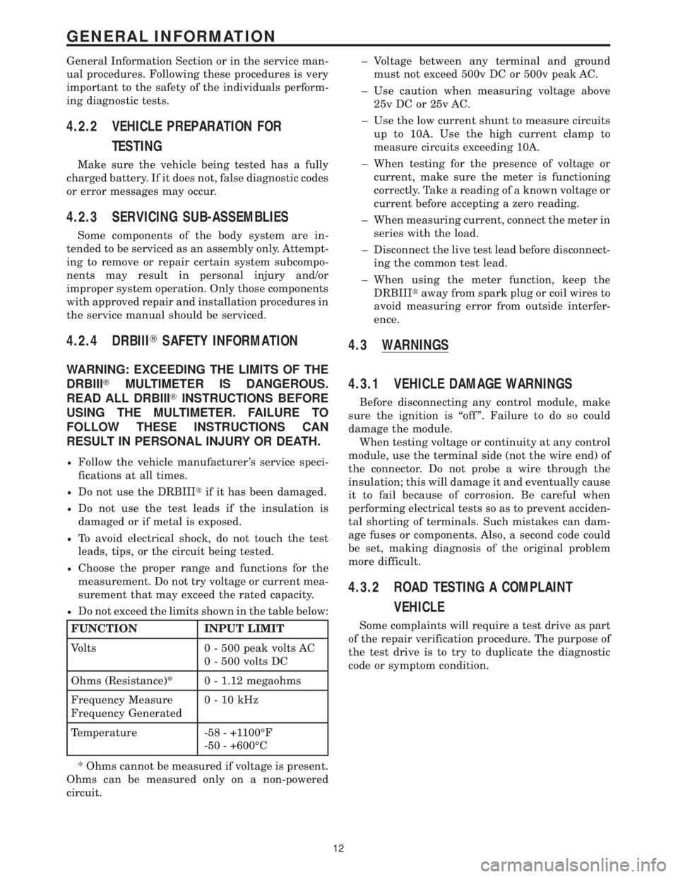
General Information Section or in the service man-
ual procedures. Following these procedures is very
important to the safety of the individuals perform-
ing diagnostic tests.
4.2.2 VEHICLE PREPARATION FOR
TESTING
Make sure the vehicle being tested has a fully
charged battery. If it does not, false diagnostic codes
or error messages may occur.
4.2.3 SERVICING SUB-ASSEMBLIES
Some components of the body system are in-
tended to be serviced as an assembly only. Attempt-
ing to remove or repair certain system subcompo-
nents may result in personal injury and/or
improper system operation. Only those components
with approved repair and installation procedures in
the service manual should be serviced.
4.2.4 DRBIIITSAFETY INFORMATION
WARNING: EXCEEDING THE LIMITS OF THE
DRBIIITMULTIMETER IS DANGEROUS.
READ ALL DRBIIITINSTRUCTIONS BEFORE
USING THE MULTIMETER. FAILURE TO
FOLLOW THESE INSTRUCTIONS CAN
RESULT IN PERSONAL INJURY OR DEATH.
²Follow the vehicle manufacturer 's service speci-
fications at all times.
²Do not use the DRBIIItif it has been damaged.
²Do not use the test leads if the insulation is
damaged or if metal is exposed.
²To avoid electrical shock, do not touch the test
leads, tips, or the circuit being tested.
²Choose the proper range and functions for the
measurement. Do not try voltage or current mea-
surement that may exceed the rated capacity.
²Do not exceed the limits shown in the table below:
FUNCTION INPUT LIMIT
Volts 0 - 500 peak volts AC
0 - 500 volts DC
Ohms (Resistance)* 0 - 1.12 megaohms
Frequency Measure
Frequency Generated0-10kHz
Temperature -58 - +1100ÉF
-50 - +600ÉC
* Ohms cannot be measured if voltage is present.
Ohms can be measured only on a non-powered
circuit.± Voltage between any terminal and ground
must not exceed 500v DC or 500v peak AC.
± Use caution when measuring voltage above
25v DC or 25v AC.
± Use the low current shunt to measure circuits
up to 10A. Use the high current clamp to
measure circuits exceeding 10A.
± When testing for the presence of voltage or
current, make sure the meter is functioning
correctly. Take a reading of a known voltage or
current before accepting a zero reading.
± When measuring current, connect the meter in
series with the load.
± Disconnect the live test lead before disconnect-
ing the common test lead.
± When using the meter function, keep the
DRBIIItaway from spark plug or coil wires to
avoid measuring error from outside interfer-
ence.
4.3 WARNINGS
4.3.1 VEHICLE DAMAGE WARNINGS
Before disconnecting any control module, make
sure the ignition is ``off ''. Failure to do so could
damage the module.
When testing voltage or continuity at any control
module, use the terminal side (not the wire end) of
the connector. Do not probe a wire through the
insulation; this will damage it and eventually cause
it to fail because of corrosion. Be careful when
performing electrical tests so as to prevent acciden-
tal shorting of terminals. Such mistakes can dam-
age fuses or components. Also, a second code could
be set, making diagnosis of the original problem
more difficult.
4.3.2 ROAD TESTING A COMPLAINT
VEHICLE
Some complaints will require a test drive as part
of the repair verification procedure. The purpose of
the test drive is to try to duplicate the diagnostic
code or symptom condition.
12
GENERAL INFORMATION
Page 32 of 2305
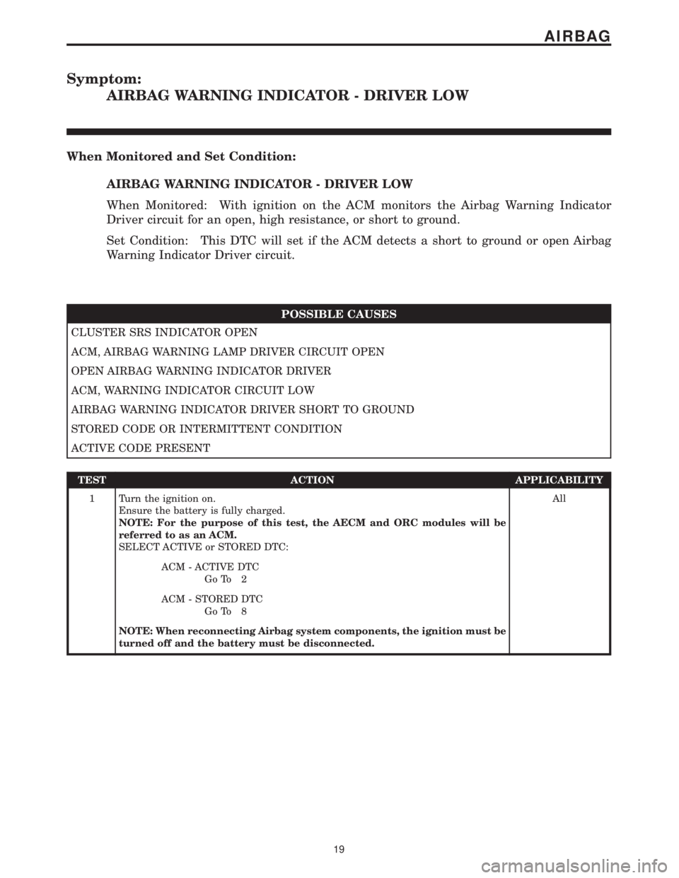
Symptom:
AIRBAG WARNING INDICATOR - DRIVER LOW
When Monitored and Set Condition:
AIRBAG WARNING INDICATOR - DRIVER LOW
When Monitored: With ignition on the ACM monitors the Airbag Warning Indicator
Driver circuit for an open, high resistance, or short to ground.
Set Condition: This DTC will set if the ACM detects a short to ground or open Airbag
Warning Indicator Driver circuit.
POSSIBLE CAUSES
CLUSTER SRS INDICATOR OPEN
ACM, AIRBAG WARNING LAMP DRIVER CIRCUIT OPEN
OPEN AIRBAG WARNING INDICATOR DRIVER
ACM, WARNING INDICATOR CIRCUIT LOW
AIRBAG WARNING INDICATOR DRIVER SHORT TO GROUND
STORED CODE OR INTERMITTENT CONDITION
ACTIVE CODE PRESENT
TEST ACTION APPLICABILITY
1 Turn the ignition on.
Ensure the battery is fully charged.
NOTE: For the purpose of this test, the AECM and ORC modules will be
referred to as an ACM.
SELECT ACTIVE or STORED DTC:All
ACM - ACTIVE DTC
Go To 2
ACM - STORED DTC
Go To 8
NOTE: When reconnecting Airbag system components, the ignition must be
turned off and the battery must be disconnected.
19
AIRBAG
Page 33 of 2305
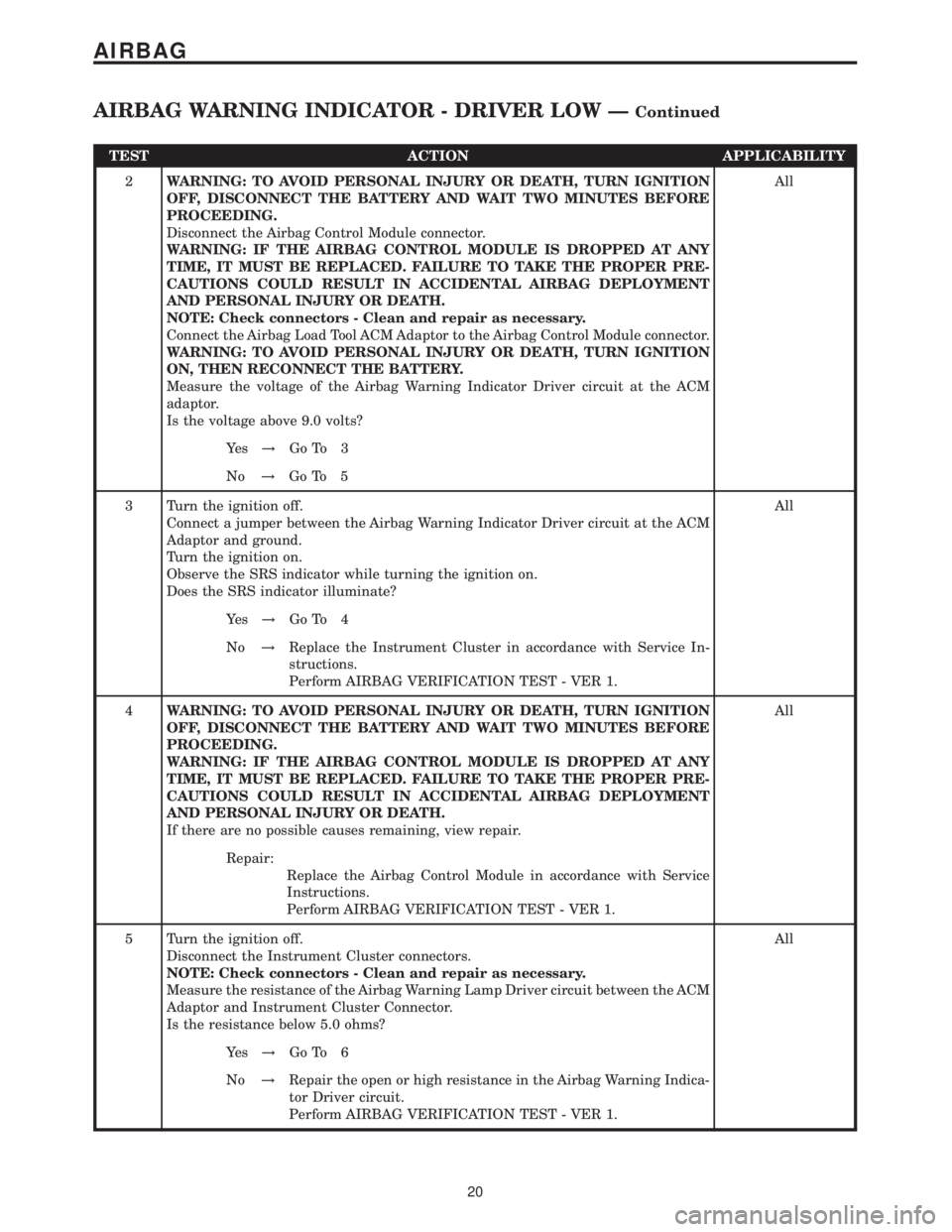
TEST ACTION APPLICABILITY
2WARNING: TO AVOID PERSONAL INJURY OR DEATH, TURN IGNITION
OFF, DISCONNECT THE BATTERY AND WAIT TWO MINUTES BEFORE
PROCEEDING.
Disconnect the Airbag Control Module connector.
WARNING: IF THE AIRBAG CONTROL MODULE IS DROPPED AT ANY
TIME, IT MUST BE REPLACED. FAILURE TO TAKE THE PROPER PRE-
CAUTIONS COULD RESULT IN ACCIDENTAL AIRBAG DEPLOYMENT
AND PERSONAL INJURY OR DEATH.
NOTE: Check connectors - Clean and repair as necessary.
Connect the Airbag Load Tool ACM Adaptor to the Airbag Control Module connector.
WARNING: TO AVOID PERSONAL INJURY OR DEATH, TURN IGNITION
ON, THEN RECONNECT THE BATTERY.
Measure the voltage of the Airbag Warning Indicator Driver circuit at the ACM
adaptor.
Is the voltage above 9.0 volts?All
Ye s!Go To 3
No!Go To 5
3 Turn the ignition off.
Connect a jumper between the Airbag Warning Indicator Driver circuit at the ACM
Adaptor and ground.
Turn the ignition on.
Observe the SRS indicator while turning the ignition on.
Does the SRS indicator illuminate?All
Ye s!Go To 4
No!Replace the Instrument Cluster in accordance with Service In-
structions.
Perform AIRBAG VERIFICATION TEST - VER 1.
4WARNING: TO AVOID PERSONAL INJURY OR DEATH, TURN IGNITION
OFF, DISCONNECT THE BATTERY AND WAIT TWO MINUTES BEFORE
PROCEEDING.
WARNING: IF THE AIRBAG CONTROL MODULE IS DROPPED AT ANY
TIME, IT MUST BE REPLACED. FAILURE TO TAKE THE PROPER PRE-
CAUTIONS COULD RESULT IN ACCIDENTAL AIRBAG DEPLOYMENT
AND PERSONAL INJURY OR DEATH.
If there are no possible causes remaining, view repair.All
Repair:
Replace the Airbag Control Module in accordance with Service
Instructions.
Perform AIRBAG VERIFICATION TEST - VER 1.
5 Turn the ignition off.
Disconnect the Instrument Cluster connectors.
NOTE: Check connectors - Clean and repair as necessary.
Measure the resistance of the Airbag Warning Lamp Driver circuit between the ACM
Adaptor and Instrument Cluster Connector.
Is the resistance below 5.0 ohms?All
Ye s!Go To 6
No!Repair the open or high resistance in the Airbag Warning Indica-
tor Driver circuit.
Perform AIRBAG VERIFICATION TEST - VER 1.
20
AIRBAG
AIRBAG WARNING INDICATOR - DRIVER LOW ÐContinued