2006 MERCEDES-BENZ SPRINTER fuse
[x] Cancel search: fusePage 857 of 2305
actuators.These outputs allow the CTM the ability to
control numerous accessory systems in the vehicle.
The CTM monitors its own internal circuitry as
well as many of its input and output circuits, and
will store a Diagnostic Trouble Code (DTC) in elec-
tronic memory for any failure it detects. These DTCs
can be retrieved and diagnosed using a DRBIIItscan
tool. Refer to the appropriate diagnostic information.
HARD WIRED INPUTS
The hard wired inputs to the CTM include the fol-
lowing:
²Fused B(+)
²Fused ignition switch output (run-acc)
²Fused ignition switch output (run-start)
²Ground
²Key-in ignition switch sense
²Sliding door switch sense
²Passenger door switch sense
²Driver door switch sense
²PCI bus circuit
HARD WIRED OUTPUTS
The hard wired outputs of the CTM include the fol-
lowing:
²Door lock relay output
²Door unlock relay output
²VTSS indicator driver
MESSAGING
The CTM uses the following messages received
from other electronic modules over the PCI data bus:
²Airbag Deploy (ACM)
²Beep request (CMTC)
²Charging System Failure (PCM)
²Chime request (EMIC)
²Engine RPM (PCM)
²OK to Arm VTSS (PCM)
²Security indicator request (SKIM)
²System Voltage (PCM)
²Valid/Invalid Key (SKIM)
²Vehicle Distance (PCM)
²Vehicle Speed (PCM)
DIAGNOSIS AND TESTING - CENTRAL TIMER
MODULE
WARNING: To avoid personal injury or death, on
vehicles equipped with airbags, disable the supple-
mental restraint system before attempting any
steering wheel, steering column, airbag, seat belt
tensioner, or instrument panel component diagno-
sis or service. Disconnect and isolate the battery
negative (ground) cable, then wait two minutes for
the system capacitor to discharge before perform-
ing further diagnosis or service. This is the only
sure way to disable the supplemental restraint sys-tem. Failure to take the proper precautions could
result in accidental airbag deployment.
The hard wired inputs to and outputs from the
central timer module (CTM) may be diagnosed and
tested using conventional diagnostic tools and meth-
ods. Refer to the appropriate wiring information.
However, conventional diagnostic methods may not
prove conclusive in the diagnosis of the CTM. In
order to obtain conclusive testing of the CTM, the
programmable communications interface (PCI) data
bus network and all of the modules that provide
inputs to or receive outputs from the CTM must also
be checked. The most reliable, efficient, and accurate
means to diagnose the CTM, the PCI data bus net-
work, and the modules that provide inputs to, or
receive outputs from, the CTM requires the use of a
DRBIIItscan tool. Refer to the appropriate diagnos-
tic information.
REMOVAL
(1) Disconnect and isolate the battery negative
cable.
(2) Slide the driver seat to the full forward posi-
tion.
(3) Disconnect the wire harness connector for the
seat belt latch. (Fig. 1).
(4) Remove the screws that secure the closeout
panel beneathe the driver seat cushion and remove
the panel.
(5) Remove the screws that secure the central
timer module to the bracket.
(6) Disconnect the wire harness connectors from
the central timer module.
(7) Remove the central timer module from the
vehicle.
8E - 2 ELECTRONIC CONTROL MODULESVA
Page 875 of 2305
(3) Using a voltmeter connected to the battery
posts (see the instructions provided by the manufac-
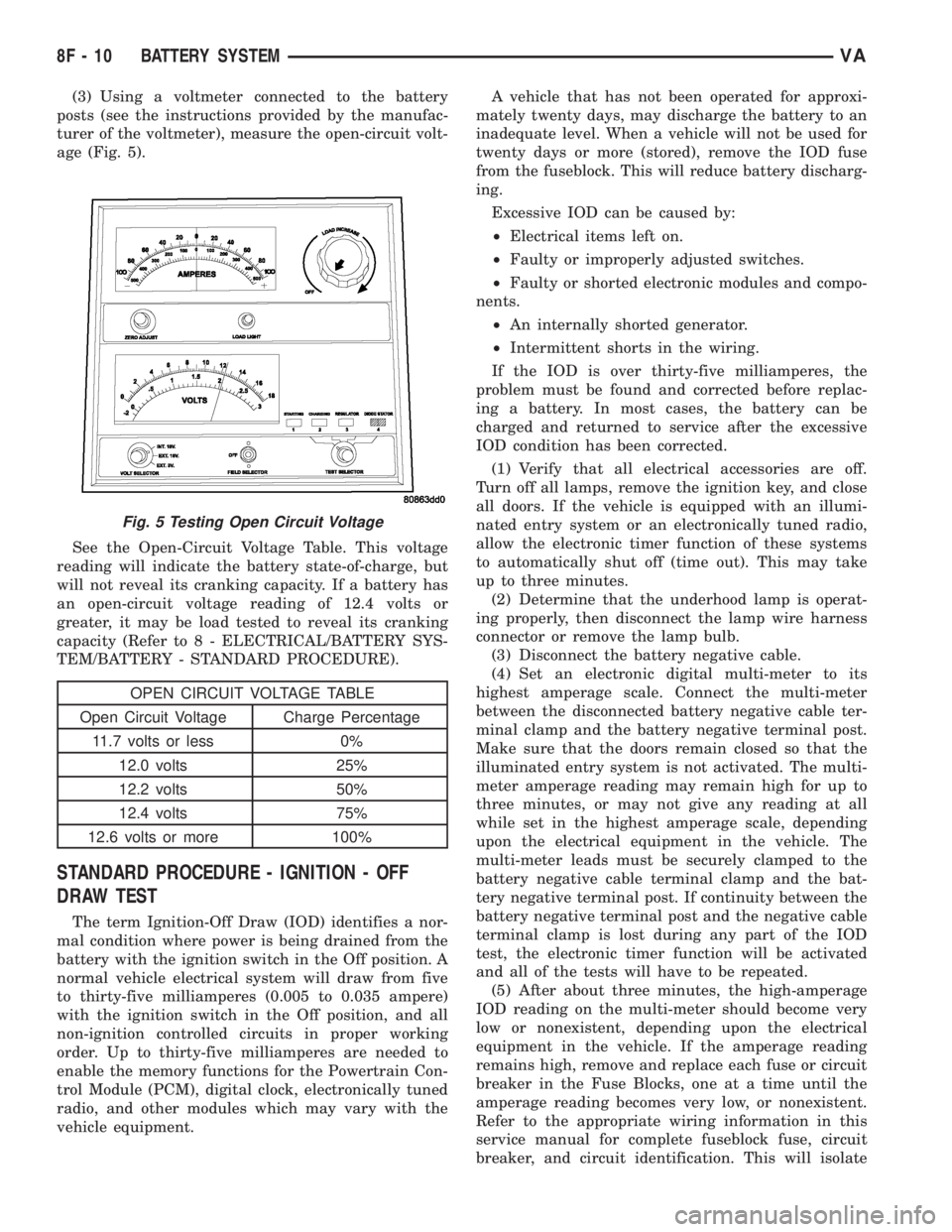
turer of the voltmeter), measure the open-circuit volt-
age (Fig. 5).
See the Open-Circuit Voltage Table. This voltage
reading will indicate the battery state-of-charge, but
will not reveal its cranking capacity. If a battery has
an open-circuit voltage reading of 12.4 volts or
greater, it may be load tested to reveal its cranking
capacity (Refer to 8 - ELECTRICAL/BATTERY SYS-
TEM/BATTERY - STANDARD PROCEDURE).
OPEN CIRCUIT VOLTAGE TABLE
Open Circuit Voltage Charge Percentage
11.7 volts or less 0%
12.0 volts 25%
12.2 volts 50%
12.4 volts 75%
12.6 volts or more 100%
STANDARD PROCEDURE - IGNITION - OFF
DRAW TEST
The term Ignition-Off Draw (IOD) identifies a nor-
mal condition where power is being drained from the
battery with the ignition switch in the Off position. A
normal vehicle electrical system will draw from five
to thirty-five milliamperes (0.005 to 0.035 ampere)
with the ignition switch in the Off position, and all
non-ignition controlled circuits in proper working
order. Up to thirty-five milliamperes are needed to
enable the memory functions for the Powertrain Con-
trol Module (PCM), digital clock, electronically tuned
radio, and other modules which may vary with the
vehicle equipment.A vehicle that has not been operated for approxi-
mately twenty days, may discharge the battery to an
inadequate level. When a vehicle will not be used for
twenty days or more (stored), remove the IOD fuse
from the fuseblock. This will reduce battery discharg-
ing.
Excessive IOD can be caused by:
²Electrical items left on.
²Faulty or improperly adjusted switches.
²Faulty or shorted electronic modules and compo-
nents.
²An internally shorted generator.
²Intermittent shorts in the wiring.
If the IOD is over thirty-five milliamperes, the
problem must be found and corrected before replac-
ing a battery. In most cases, the battery can be
charged and returned to service after the excessive
IOD condition has been corrected.
(1) Verify that all electrical accessories are off.
Turn off all lamps, remove the ignition key, and close
all doors. If the vehicle is equipped with an illumi-
nated entry system or an electronically tuned radio,
allow the electronic timer function of these systems
to automatically shut off (time out). This may take
up to three minutes.
(2) Determine that the underhood lamp is operat-
ing properly, then disconnect the lamp wire harness
connector or remove the lamp bulb.
(3) Disconnect the battery negative cable.
(4) Set an electronic digital multi-meter to its
highest amperage scale. Connect the multi-meter
between the disconnected battery negative cable ter-
minal clamp and the battery negative terminal post.
Make sure that the doors remain closed so that the
illuminated entry system is not activated. The multi-
meter amperage reading may remain high for up to
three minutes, or may not give any reading at all
while set in the highest amperage scale, depending
upon the electrical equipment in the vehicle. The
multi-meter leads must be securely clamped to the
battery negative cable terminal clamp and the bat-
tery negative terminal post. If continuity between the
battery negative terminal post and the negative cable
terminal clamp is lost during any part of the IOD
test, the electronic timer function will be activated
and all of the tests will have to be repeated.
(5) After about three minutes, the high-amperage
IOD reading on the multi-meter should become very
low or nonexistent, depending upon the electrical
equipment in the vehicle. If the amperage reading
remains high, remove and replace each fuse or circuit
breaker in the Fuse Blocks, one at a time until the
amperage reading becomes very low, or nonexistent.
Refer to the appropriate wiring information in this
service manual for complete fuseblock fuse, circuit
breaker, and circuit identification. This will isolate
Fig. 5 Testing Open Circuit Voltage
8F - 10 BATTERY SYSTEMVA
Page 876 of 2305
each circuit and identify the circuit that is the source
of the high-amperage IOD. If the amperage reading
remains high after removing and replacing each fuse
and circuit breaker, disconnect the wire harness from
the generator. If the amperage reading now becomes
very low or nonexistent, refer to Charging System for
the proper charging system diagnosis and testing
procedures. After the high-amperage IOD has been
corrected, switch the multi-meter to progressively
lower amperage scales and, if necessary, repeat the
fuse and circuit breaker remove-and-replace process
to identify and correct all sources of excessive IOD. It
is now safe to select the lowest milliampere scale of
the multi-meter to check the low-amperage IOD.
CAUTION: Do not open any doors, or turn on any
electrical accessories with the lowest milliampere
scale selected, or the multi-meter may be damaged.
(6) Observe the multi-meter reading. The low-am-
perage IOD should not exceed thirty-five milliam-
peres (0.035 ampere). If the current draw exceeds
thirty-five milliamperes, isolate each circuit using the
fuse and circuit breaker remove-and-replace process
in Step 5. The multi-meter reading will drop to
within the acceptable limit when the source of the
excessive current draw is disconnected. Repair this
circuit as required; whether a wiring short, incorrect
switch adjustment, or a component failure is at fault.
STANDARD PROCEDURE - USING MICRO 420
BATTERY TESTER
Always use the Micro 420 Instruction Manual that
was supplied with the tester as a reference. If theInstruction Manual is not available the following pro-
cedure can be used:
WARNING: ALWAYS WEAR APPROPRIATE EYE
PROTECTION AND USE EXTREME CAUTION WHEN
WORKING WITH BATTERIES.
BATTERY TESTING
(1) If testing the battery OUT-OF-VEHICLE, clean
the battery terminals with a wire brush before test-
ing. If the battery is equipped with side post termi-
nals, install and tighten the supplied lead terminal
stud adapters. Do not use steel bolts. Failure to prop-
erly install the stud adapters, or using stud adapters
that are dirty or worn-out may result in false test
readings.
(2) If testing the battery IN-THE-VEHICLE, make
certain all of the vehicle accessory loads are OFF,
including the ignition.The preferred test position
is at the battery terminal. If the battery is not
accessible, you may test using both the positive and
negative jumper posts. Select TESTING AT JUMPER
POST when connecting to that location.
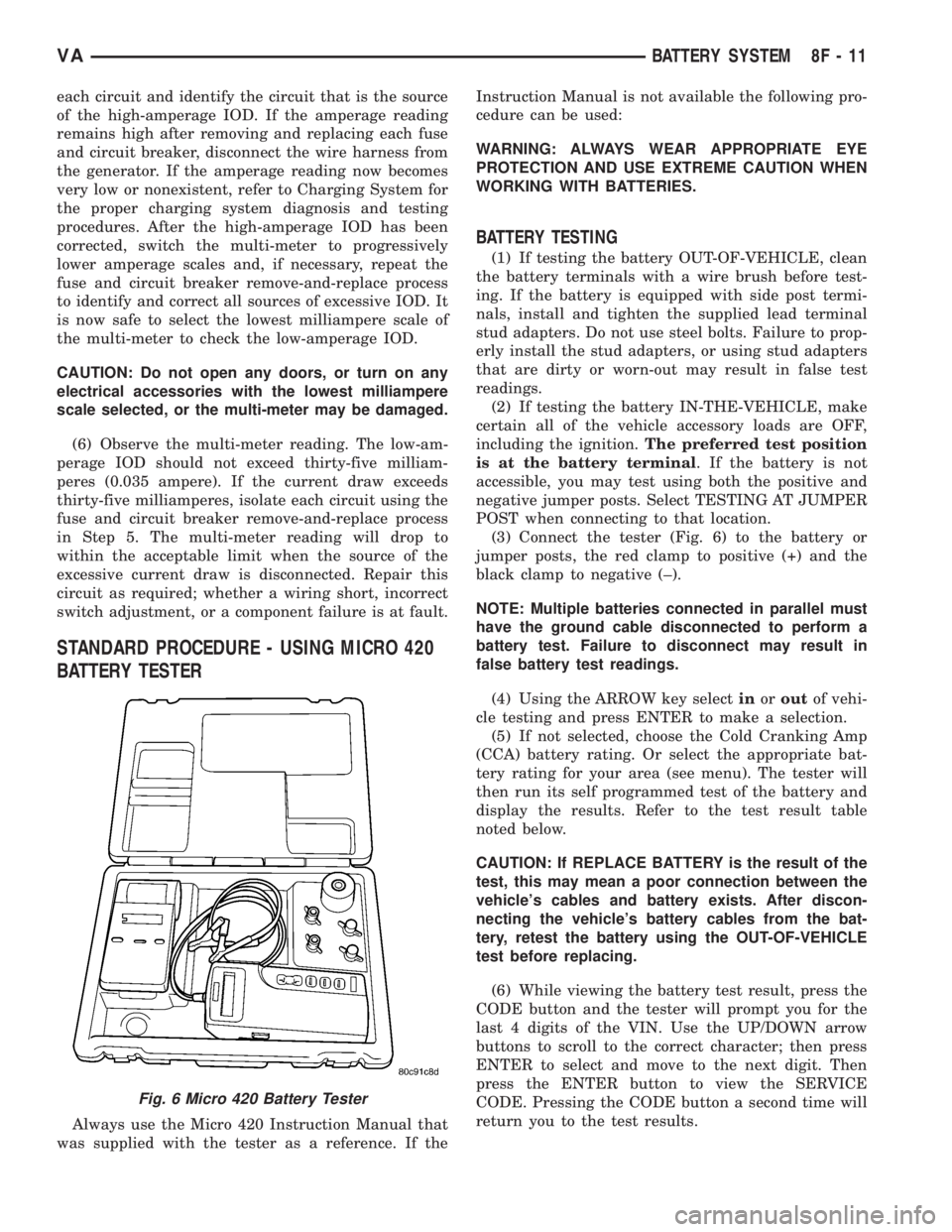
(3) Connect the tester (Fig. 6) to the battery or
jumper posts, the red clamp to positive (+) and the
black clamp to negative (±).
NOTE: Multiple batteries connected in parallel must
have the ground cable disconnected to perform a
battery test. Failure to disconnect may result in
false battery test readings.
(4) Using the ARROW key selectinoroutof vehi-
cle testing and press ENTER to make a selection.
(5) If not selected, choose the Cold Cranking Amp
(CCA) battery rating. Or select the appropriate bat-
tery rating for your area (see menu). The tester will
then run its self programmed test of the battery and
display the results. Refer to the test result table
noted below.
CAUTION: If REPLACE BATTERY is the result of the
test, this may mean a poor connection between the
vehicle's cables and battery exists. After discon-
necting the vehicle's battery cables from the bat-
tery, retest the battery using the OUT-OF-VEHICLE
test before replacing.
(6) While viewing the battery test result, press the
CODE button and the tester will prompt you for the
last 4 digits of the VIN. Use the UP/DOWN arrow
buttons to scroll to the correct character; then press
ENTER to select and move to the next digit. Then
press the ENTER button to view the SERVICE
CODE. Pressing the CODE button a second time will
return you to the test results.
Fig. 6 Micro 420 Battery Tester
VABATTERY SYSTEM 8F - 11
Page 900 of 2305
INSTALLATION
(1) Raise and support vehicle.
(2) Position starter motor to transmission housing.
(3) Install 2 mounting bolts. Refer to Torque Spec-
ifications.
(4) Lower vehicle.
(5) Connect battery cable and solenoid wiring to
solenoid (2 nuts). Refer to Torque Specifications.
(6) Position wiring harness trough and install
retaining bolt.
(7) Install new nylon tie-wraps to wiring trough.
(8) Connect negative battery cable.
STARTER MOTOR RELAY
DESCRIPTION
The starter relay is an electromechanical device
that switches battery current to the pull-in coil of the
starter solenoid when ignition switch is turned to
Start position. The starter relay is located in the
Fuse/Relay Block. The Fuse/Relay Block is located
under, and to the left side of the drivers seat. See
Fuse/Relay Block cover for relay identification and
location.
The starter relay is an International Standards
Organization (ISO) relay. Relays conforming to ISO
specifications have common physical dimensions, cur-rent capacities, terminal patterns, and terminal func-
tions.
The starter relay cannot be repaired or adjusted
and, if faulty or damaged, it must be replaced.
REMOVAL
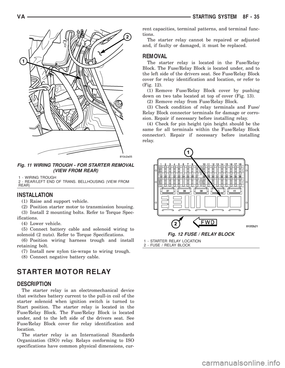
The starter relay is located in the Fuse/Relay
Block. The Fuse/Relay Block is located under, and to
the left side of the drivers seat. See Fuse/Relay Block
cover for relay identification and location, or refer to
(Fig. 12).
(1) Remove Fuse/Relay Block cover by pushing
down on two tabs located at top of cover (Fig. 13).
(2) Remove relay from Fuse/Relay Block.
(3) Check condition of relay terminals and Fuse/
Relay Block connector terminals for damage or corro-
sion. Repair if necessary before installing relay.
(4) Check for pin height (pin height should be the
same for all terminals within the Fuse/Relay Block
connector). Repair if necessary before installing
relay.
Fig. 11 WIRING TROUGH - FOR STARTER REMOVAL
(VIEW FROM REAR)
1 - WIRING TROUGH
2 - REAR/LEFT END OF TRANS. BELLHOUSING (VIEW FROM
REAR)
Fig. 12 FUSE / RELAY BLOCK
1 - STARTER RELAY LOCATION
2 - FUSE / RELAY BLOCK
VASTARTING SYSTEM 8F - 35
Page 901 of 2305

INSTALLATION
The starter relay is located in the Fuse/Relay
Block. The Fuse/Relay Block is located under, and to
the left side of the drivers seat. See Fuse/Relay Block
cover for relay identification and location, or refer to
(Fig. 12).
(1) Install relay into Fuse/Relay Block.
(2) Install cover to side of Fuse/Relay Block (snaps
on).
Fig. 13 FUSE / RELAY BLOCK COVER
1 - LEFT SIDE OF DRIVERS SEAT
2 - FUSE / RELAY BLOCK
3 - RELEASE TABS (2)
4 - COVER (ACCESS PANEL)
8F - 36 STARTING SYSTEMVA
Page 902 of 2305

HEATED SYSTEMS
TABLE OF CONTENTS
page page
HEATED GLASS........................... 1
HEATED MIRRORS......................... 9HEATED SEATS........................... 10
HEATED GLASS
TABLE OF CONTENTS
page page
HEATED GLASS
DESCRIPTION..........................1
OPERATION............................1
DIAGNOSIS AND TESTING
ELECTRIC BACKLIGHT (EBL) SYSTEM.....2
REAR WINDOW DEFOGGER RELAY
DESCRIPTION..........................3
OPERATION............................3
REMOVAL.............................4
INSTALLATION..........................4REAR WINDOW DEFOGGER SWITCH
DESCRIPTION..........................4
OPERATION............................4
DIAGNOSIS AND TESTING
REAR WINDOW DEFOGGER SWITCH......5
REMOVAL.............................6
INSTALLATION..........................6
REAR WINDOW DEFOGGER GRID
STANDARD PROCEDURE
GRID LINE AND TERMINAL REPAIR........7
HEATED GLASS
DESCRIPTION
CAUTION: Grid lines can be damaged or scraped
off with sharp instruments. Care should be taken in
cleaning glass or removing foreign materials,
decals or stickers. Normal glass cleaning solvents
or hot water used with rags or toweling is recom-
mended.
The rear window defogger system, also known as
the electric backlight (EBL), consists of a backglass
with two vertical bus bars linked by a series of grid
lines fired onto the inside surface of the rear window.
The EBL system is turned On or Off by a control
switch (Fig. 1) located in the instrument panel near
the right side of the steering wheel, which sends a
request signal to the rear window defogger module
that operates the left and right rear window defogger
relays located in the fuse/relay block under the driv-
ers seat.
Circuit protection is provided by a 30 amp fuse
also located in the fuse/relay block.
OPERATION
When the rear window defogger switch is pressed
to the On position, current is directed through the
switch to the rear window defogger module. The rear
window defogger module then grounds the control
side of the left and right rear window defogger (EBL)
Fig. 1 Rear Window Defogger Switch
1 - REAR WINDOW DEFOGGER SWITCH
2 - INSTRUMENT PANEL
VAHEATED SYSTEMS 8G - 1
Page 903 of 2305
relays which allows battery current to flow to the
rear window defogger grid lines. The heated grid
lines heat the rear glass to help clear the rear win-
dow surfaces of fog or frost.
The electric backlight (EBL) system is controlled
by the EBL timing circuity, which is integral to the
rear window defogger module. A yellow indicator in
the switch will illuminate to indicate when the EBL
system is turned on.
NOTE: The EBL system turns off automatically after
approximately 10 minutes of initial operation. Each
following activation cycle of the EBL system will
last approximately five minutes.
The EBL system will be automatically turned off
after a programmed time interval of about ten min-
utes. After the initial time interval has expired, if the
rear window defogger switch is pressed to the On
position again during the same ignition cycle, the
EBL system will automatically turn off after about
five minutes.
The EBL system will automatically shut off if the
ignition switch is turned to the Off position, or it can
be turned off manually by pressing the defogger
switch a second time.
DIAGNOSIS AND TESTING
ELECTRIC BACKLIGHT (EBL) SYSTEM
NOTE: Illumination of the defogger switch indicator
lamp means that there is electrical current available
at the output of the rear window defogger logic cir-
cuitry, but does not confirm that the electrical cur-
rent is reaching the rear glass heating grid lines.
NOTE: For circuit descriptions and diagrams of the
EBL system, refer to 8W - WIRING DIAGRAM
INFORMATION.
Operation of the electrical backlight (EBL) system
can be confirmed by the following:
(1) Turn the ignition switch to the On position. Set
the rear window defogger switch in the On position.
The rear window defogger operation can be checked
by feeling the rear window glass. A distinct difference
in temperature between the grid lines and the adja-
cent clear glass should be detected within three to
four minutes of operation.
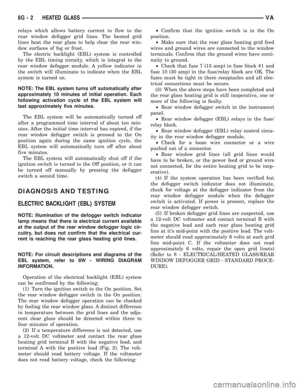
(2) If a temperature difference is not detected, use
a 12-volt DC voltmeter and contact the rear glass
heating grid terminal B with the negative lead, and
terminal A with the positive lead (Fig. 2). The volt-
meter should read battery voltage. If the voltmeter
does not read battery voltage, check the following:²Confirm that the ignition switch is in the On
position.
²Make sure that the rear glass heating grid feed
wires and ground wires are connected to the window
terminals. Confirm that the ground wires have conti-
nuity to ground.
²Check that fuse 7 (15 amp) in fuse block #1 and
fuse 10 (30 amp) in the fuse/relay block are OK. The
fuses must be tight in there receptacles and all elec-
trical connections must be secure.
(3) When the above steps have been completed and
the rear glass heating grid is still inoperative, one or
more of the following is faulty.
²Rear window defogger switch in the instrument
panel.
²Rear window defogger (EBL) relays in the fuse/
relay block.
²Rear window defogger (EBL) relay control circu-
ity in the rear window defogger module.
²Check for a loose wire connector or a wire
pushed out of a connector.
²Rear window grid lines (all grid lines would
have to be broken, or the power feed or ground wire
not connected, for the entire heating grid to be inop-
erative).
(4) If the system operation has been verified but
the defogger switch indicator does not illuminate,
check for voltage at the defogger indicator from the
rear window defogger module when the defogger
switch is activated. If power is present, replace the
rear window defogger switch.
(5) If broken defogger grid lines are suspected, use
a 12-volt DC voltmeter and contact terminal B with
the negative lead and each rear glass heating grid
line at it's mid-point with the positive lead. The volt-
meter should read approximately 6 volts at each grid
line mid-point C. If the voltmeter does not read
approximately 6 volts, repair the open grid line(s)
(Refer to 8 - ELECTRICAL/HEATED GLASS/REAR
WINDOW DEFOGGER GRID - STANDARD PROCE-
DURE).
8G - 2 HEATED GLASSVA
Page 904 of 2305
REAR WINDOW DEFOGGER
RELAY
DESCRIPTION
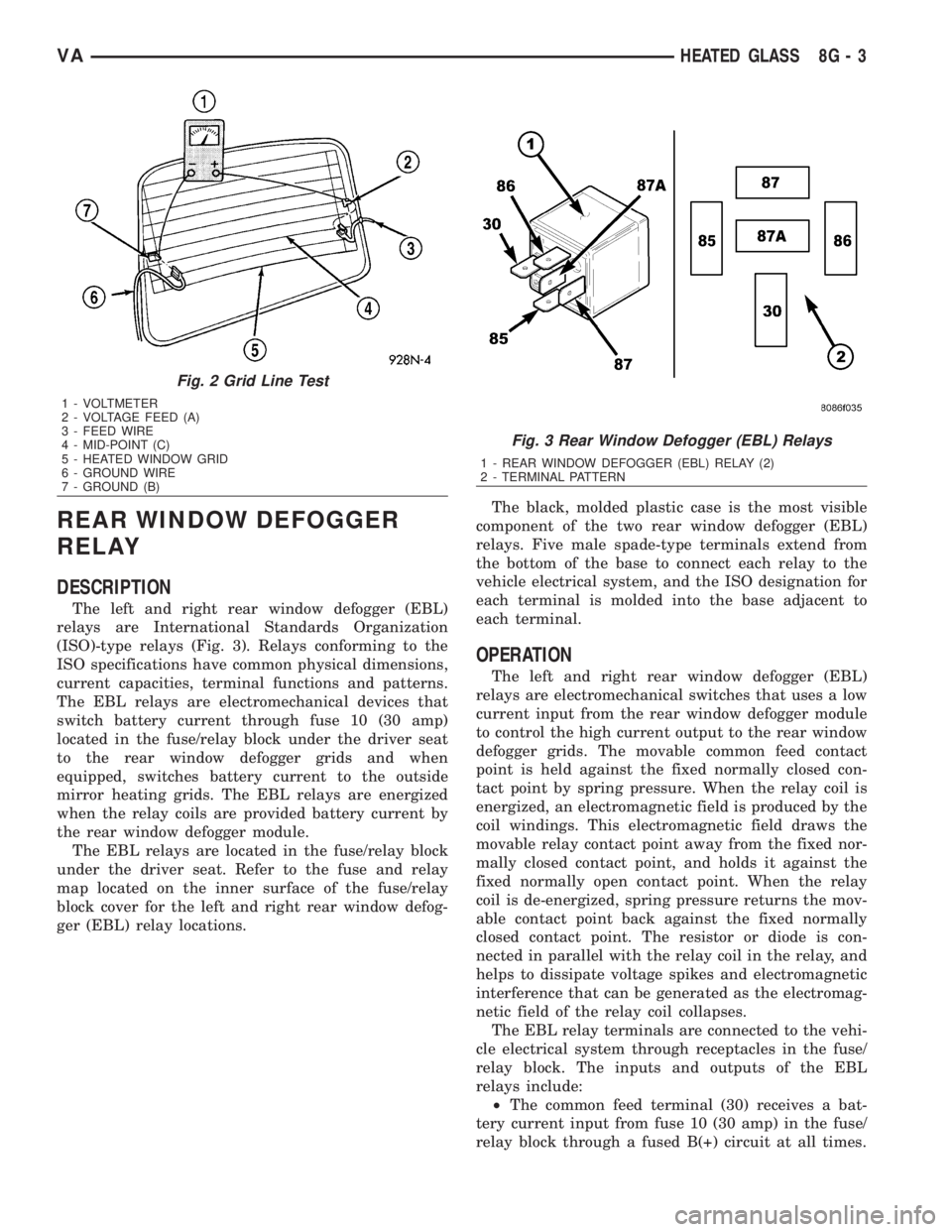
The left and right rear window defogger (EBL)
relays are International Standards Organization
(ISO)-type relays (Fig. 3). Relays conforming to the
ISO specifications have common physical dimensions,
current capacities, terminal functions and patterns.
The EBL relays are electromechanical devices that
switch battery current through fuse 10 (30 amp)
located in the fuse/relay block under the driver seat
to the rear window defogger grids and when
equipped, switches battery current to the outside
mirror heating grids. The EBL relays are energized
when the relay coils are provided battery current by
the rear window defogger module.
The EBL relays are located in the fuse/relay block
under the driver seat. Refer to the fuse and relay
map located on the inner surface of the fuse/relay
block cover for the left and right rear window defog-
ger (EBL) relay locations.The black, molded plastic case is the most visible
component of the two rear window defogger (EBL)
relays. Five male spade-type terminals extend from
the bottom of the base to connect each relay to the
vehicle electrical system, and the ISO designation for
each terminal is molded into the base adjacent to
each terminal.
OPERATION
The left and right rear window defogger (EBL)
relays are electromechanical switches that uses a low
current input from the rear window defogger module
to control the high current output to the rear window
defogger grids. The movable common feed contact
point is held against the fixed normally closed con-
tact point by spring pressure. When the relay coil is
energized, an electromagnetic field is produced by the
coil windings. This electromagnetic field draws the
movable relay contact point away from the fixed nor-
mally closed contact point, and holds it against the
fixed normally open contact point. When the relay
coil is de-energized, spring pressure returns the mov-
able contact point back against the fixed normally
closed contact point. The resistor or diode is con-
nected in parallel with the relay coil in the relay, and
helps to dissipate voltage spikes and electromagnetic
interference that can be generated as the electromag-
netic field of the relay coil collapses.
The EBL relay terminals are connected to the vehi-
cle electrical system through receptacles in the fuse/
relay block. The inputs and outputs of the EBL
relays include:
²The common feed terminal (30) receives a bat-
tery current input from fuse 10 (30 amp) in the fuse/
relay block through a fused B(+) circuit at all times.
Fig. 2 Grid Line Test
1 - VOLTMETER
2 - VOLTAGE FEED (A)
3 - FEED WIRE
4 - MID-POINT (C)
5 - HEATED WINDOW GRID
6 - GROUND WIRE
7 - GROUND (B)
Fig. 3 Rear Window Defogger (EBL) Relays
1 - REAR WINDOW DEFOGGER (EBL) RELAY (2)
2 - TERMINAL PATTERN
VAHEATED GLASS 8G - 3