Page 666 of 2305

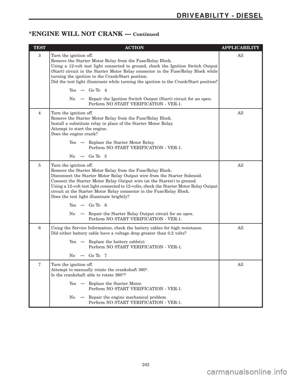
TEST ACTION APPLICABILITY
3 Turn the ignition off.
Remove the Starter Motor Relay from the Fuse/Relay Block.
Using a 12-volt test light connected to ground, check the Ignition Switch Output
(Start) circuit in the Starter Motor Relay connector in the Fuse/Relay Block while
turning the ignition to the Crank/Start position.
Did the test light illuminate while turning the ignition to the Crank/Start position?All
Ye s!Go To 4
No!Repair the Ignition Switch Output (Start) circuit for an open.
Perform NO START VERIFICATION - VER-1.
4 Turn the ignition off.
Remove the Starter Motor Relay from the Fuse/Relay Block.
Install a substitute relay in place of the Starter Motor Relay.
Attempt to start the engine.
Does the engine crank?All
Ye s!Replace the Starter Motor Relay.
Perform NO START VERIFICATION - VER-1.
No!Go To 5
5 Turn the ignition off.
Remove the Starter Motor Relay from the Fuse/Relay Block.
Disconnect the Starter Motor Relay Output wire from the Starter Solenoid.
Connect the Starter Motor Relay Output wire (at the Starter) to ground.
Using a 12-volt test light connected to 12-volts, check the Starter Motor Relay Output
circuit at the Starter Motor Relay connector in the Fuse/Relay Block.
Does the test light illuminate brightly?All
Ye s!Go To 6
No!Repair the Starter Relay Output circuit for an open.
Perform NO START VERIFICATION - VER-1.
6 Using the Service Information, check the battery cables for high resistance.
Did either battery cable have a voltage drop greater than 0.2 volts?All
Ye s!Replace the battery cable(s).
Perform NO START VERIFICATION - VER-1.
No!Go To 7
7 Turn the ignition off.
Attempt to manually rotate the crankshaft 360É.
Is the crankshaft able to rotate 360É?All
Ye s!Replace the Starter Motor.
Perform NO START VERIFICATION - VER-1.
No!Repair the engine mechanical problem.
Perform NO START VERIFICATION - VER-1.
243
DRIVEABILITY - DIESEL
*ENGINE WILL NOT CRANK ÐContinued
Page 667 of 2305

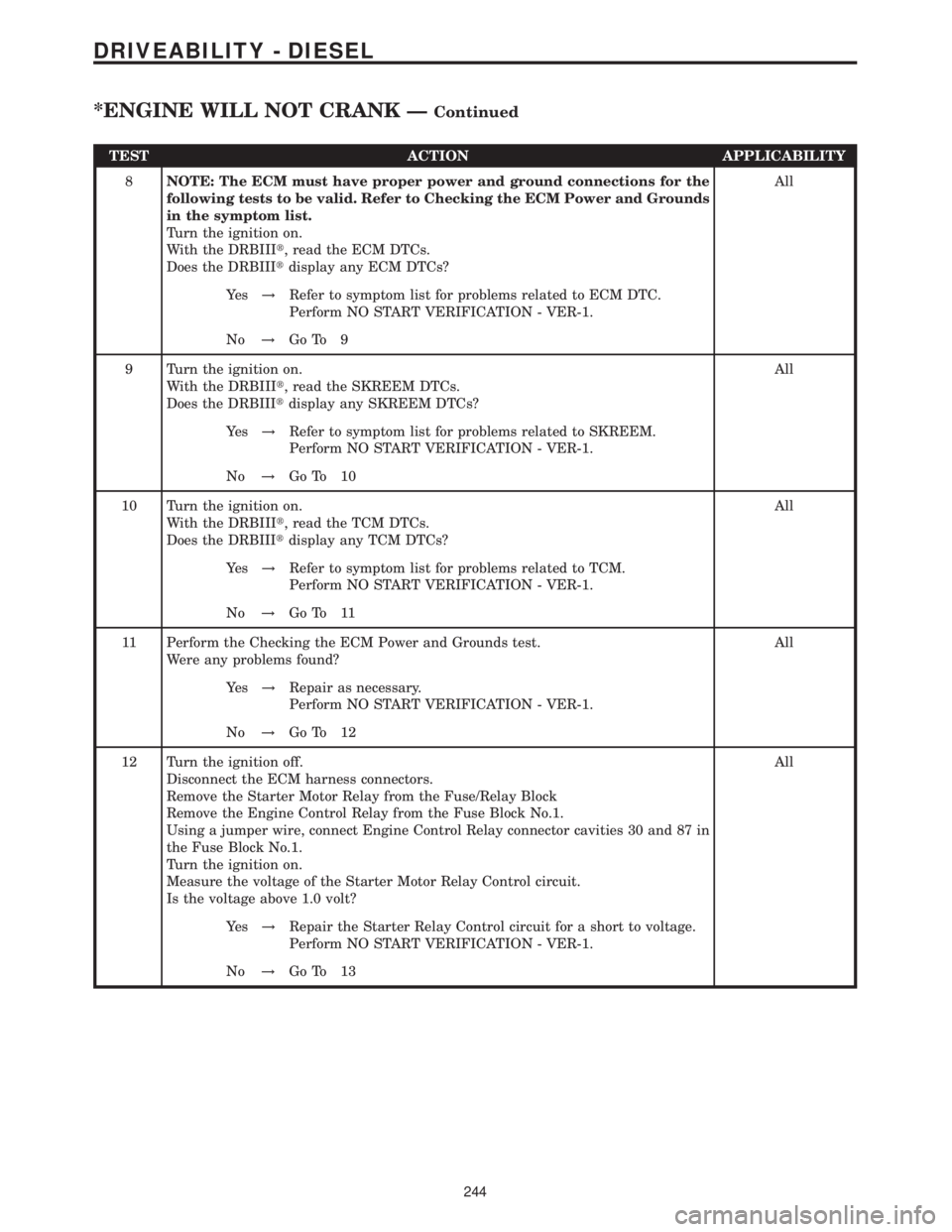
TEST ACTION APPLICABILITY
8NOTE: The ECM must have proper power and ground connections for the
following tests to be valid. Refer to Checking the ECM Power and Grounds
in the symptom list.
Turn the ignition on.
With the DRBIIIt, read the ECM DTCs.
Does the DRBIIItdisplay any ECM DTCs?All
Ye s!Refer to symptom list for problems related to ECM DTC.
Perform NO START VERIFICATION - VER-1.
No!Go To 9
9 Turn the ignition on.
With the DRBIIIt, read the SKREEM DTCs.
Does the DRBIIItdisplay any SKREEM DTCs?All
Ye s!Refer to symptom list for problems related to SKREEM.
Perform NO START VERIFICATION - VER-1.
No!Go To 10
10 Turn the ignition on.
With the DRBIIIt, read the TCM DTCs.
Does the DRBIIItdisplay any TCM DTCs?All
Ye s!Refer to symptom list for problems related to TCM.
Perform NO START VERIFICATION - VER-1.
No!Go To 11
11 Perform the Checking the ECM Power and Grounds test.
Were any problems found?All
Ye s!Repair as necessary.
Perform NO START VERIFICATION - VER-1.
No!Go To 12
12 Turn the ignition off.
Disconnect the ECM harness connectors.
Remove the Starter Motor Relay from the Fuse/Relay Block
Remove the Engine Control Relay from the Fuse Block No.1.
Using a jumper wire, connect Engine Control Relay connector cavities 30 and 87 in
the Fuse Block No.1.
Turn the ignition on.
Measure the voltage of the Starter Motor Relay Control circuit.
Is the voltage above 1.0 volt?All
Ye s!Repair the Starter Relay Control circuit for a short to voltage.
Perform NO START VERIFICATION - VER-1.
No!Go To 13
244
DRIVEABILITY - DIESEL
*ENGINE WILL NOT CRANK ÐContinued
Page 668 of 2305

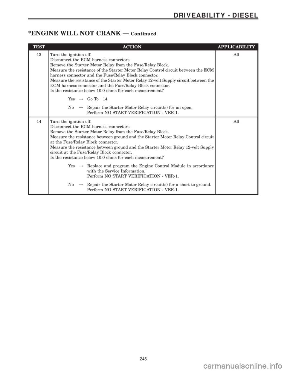
TEST ACTION APPLICABILITY
13 Turn the ignition off.
Disconnect the ECM harness connectors.
Remove the Starter Motor Relay from the Fuse/Relay Block.
Measure the resistance of the Starter Motor Relay Control circuit between the ECM
harness connector and the Fuse/Relay Block connector.
Measure the resistance of the Starter Motor Relay 12-volt Supply circuit between the
ECM harness connector and the Fuse/Relay Block connector.
Is the resistance below 10.0 ohms for each measurement?All
Ye s!Go To 14
No!Repair the Starter Motor Relay circuit(s) for an open.
Perform NO START VERIFICATION - VER-1.
14 Turn the ignition off.
Disconnect the ECM harness connectors.
Remove the Starter Motor Relay from the Fuse/Relay Block.
Measure the resistance between ground and the Starter Motor Relay Control circuit
at the Fuse/Relay Block connector.
Measure the resistance between ground and the Starter Motor Relay 12-volt Supply
circuit at the Fuse/Relay Block connector.
Is the resistance below 10.0 ohms for each measurement?All
Ye s!Replace and program the Engine Control Module in accordance
with the Service Information.
Perform NO START VERIFICATION - VER-1.
No!Repair the Starter Motor Relay circuit(s) for a short to ground.
Perform NO START VERIFICATION - VER-1.
245
DRIVEABILITY - DIESEL
*ENGINE WILL NOT CRANK ÐContinued
Page 678 of 2305

9.0 CONNECTOR PINOUTS
ACCELERATOR PEDAL POSITION SENSOR (OBD)CAV CIRCUIT FUNCTION
1 18BL/DG ACCEL PEDAL POSITION SENSOR SIGNAL NO. 1
2 18BR/GY ACCEL PEDAL POSITION SENSOR GROUND NO. 2
3 18GY/DG ACCEL PEDAL POSITION SENSOR SIGNAL NO. 2
4 18BL/RD ACCEL PEDAL POSITION SENSOR 5 VOLT SUPPLY
5 18BR/BL ACCEL PEDAL POSITION SENSOR GROUND NO. 1
AIRBAG CONTROL MODULE - YELLOWCAV CIRCUIT FUNCTION
1 20BL DRIVER SEAT BELT TENSIONER LINE 2
2 20BR/YL DRIVER SEAT BELT TENSIONER LINE 1
3 20BL PASSENGER SEAT BELT TENSIONER LINE 2
4 20BR PASSENGER SEAT BELT TENSIONER LINE 1
5 20BK FUSED IGNITION SWITCH OUTPUT (RUN-START)
6 20BR GROUND
7 20YL AIRBAG WARNING INDICATOR DRIVER
8- -
9 20BK/RD K-ACM
10 20DG DRIVER AIRBAG SQUIB 1 LINE 2
11 20VT DRIVER AIRBAG SQUIB 1 LINE 1
12 - -
13 20BL/DG PASSENGER AIRBAG SQUIB 1 LINE 2
14 20BR/DG PASSENGER AIRBAG SQUIB 1 LINE 1
15 - -
16 - -
17 - -
18 - -
19 - -
20 20DG ENHANCED ACCIDENT REPORT DRIVER
21 -
22 -
23 -
24 -
25 -
BOOST PRESSURE SENSOR (OBD)CAV CIRCUIT FUNCTION
1 18BR/WT SENSOR GROUND
2 18WT/DG BOOST PRESSURE SENSOR SIGNAL
3 18WT/RD BOOST PRESSURE SENSOR 5 VOLT SUPPLY
C
O
N
N
E
C
T
O
R
P
I
N
O
U
T
S
255
CONNECTOR PINOUTS
Page 679 of 2305
BOOST PRESSURE SERVOMOTOR (OBD)CAV CIRCUIT FUNCTION
1 16YL/BK FUSED ENGINE CONTROL RELAY OUTPUT
2 16YL/WT GROUND
3- -
4 16YL/DG BOOST PRESSURE SERVOMOTOR CONTROL
5- -
CAMSHAFT POSITION SENSOR - BLACKCAV CIRCUIT FUNCTION
1 20BR/DG CAMSHAFT POSITION SENSOR GROUND
2 20YL/GY CAMSHAFT POSITION SENSOR SIGNAL
3 18RD/BL (EXCEPT OBD) CAMSHAFT POSITION SENSOR 12 VOLT SUPPLY
3 20RD/BL (OBD) CAMSHAFT POSITION SENSOR 5 VOLT SUPPLY
C
O
N
N
E
C
T
O
R
P
I
N
O
U
T
S
256
CONNECTOR PINOUTS
Page 680 of 2305

CONTROLLER ANTILOCK BRAKECAV CIRCUIT FUNCTION
1 12BR GROUND
2 12RD FUSED B(+)
3- -
4- -
5 14BR GROUND
6 14RD FUSED B(+)
7- -
8 20BK/DG SENSOR SIGNAL
9 20YL/WT SENSOR SIGNAL
10 20YL/RD SENSOR SIGNAL
11 18BL/BK K-ABS/SHIFTER ASSEMBLY
12 18BK LEFT FRONT WHEEL SPEED SENSOR (+)
13 - -
14 20WT LEFT REAR WHEEL SPEED SENSOR (+)
15 18BR RIGHT FRONT WHEEL SPEED SENSOR (-)
16 18BK RIGHT FRONT WHEEL SPEED SENSOR (+)
17 - -
18 - -
19 - -
20 20WT BRAKE SWITCH OUTPUT
21 20BR GROUND
22 - -
23 18BK/RD FUSED OPTIONAL EQUIPMENT RELAY OUTPUT
24 20DG/WT CAN C BUS (+)
25 20BR SENSOR GROUND
26 20WT/GY BRAKE PRESSURE SENSOR SIGNAL
27 18BK/BL TCS SWITCH (ASR) SENSE
28 18BR LEFT FRONT WHEEL SPEED SENSOR (-)
29 20BR LEFT REAR WHEEL SPEED SENSOR (-)
30 20BR RIGHT REAR WHEEL SPEED SENSOR (-)
31 20YL RIGHT REAR WHEEL SPEED SENSOR (+)
32 18BK/RD BRAKE LAMP SWITCH OUTPUT
33 - -
34 - -
35 - -
36 - -
37 - -
38 - -
39 20RD/BL POWER INPUT
40 20DG CAN C BUS (-)
41 20DG/YL SENSOR SIGNAL
42 20WT/RD 5 VOLT SUPPLY
CRANKCASE HEATER - BLACKCAV CIRCUIT FUNCTION
1 18BR (EXCEPT OBD) GROUND
1 18BK/RD (OBD) CRANKCASE HEATER SIGNAL
2 16BK/RD (EXCEPT OBD) FUSED ENGINE CONTROL RELAY OUTPUT
2 18BK/BR (OBD) CRANKCASE HEATER GROUND
C
O
N
N
E
C
T
O
R
P
I
N
O
U
T
S
257
CONNECTOR PINOUTS
Page 681 of 2305

CRANKSHAFT POSITION SENSOR - BLACKCAV CIRCUIT FUNCTION
1 20DG (EXCEPT OBD) CRANKSHAFT POSITION SENSOR SIGNAL NO. 2
1 20DG/WT (OBD) CRANKSHAFT POSITION SENSOR SIGNAL NO. 1
2 20DG/WT (EXCEPT OBD) CRANKSHAFT POSITION SENSOR SIGNAL NO. 1
2 20DG (OBD) CRANKSHAFT POSITION SENSOR SIGNAL NO. 2
DATA LINK CONNECTOR - BLACKCAV CIRCUIT FUNCTION
1 20WT/DG K-SKREEM
2- -
3 20DG/YL ENGINE RPM
4 20BR GROUND
5 20BR GROUND
6- -
7 20BL/YL K-ECM
8 20BK/BL/DG FUSED IGNITION SWITCH OUTPUT (RUN-START)
9 20BL/BK K-ABS/SHIFTER ASSEMBLY
10 - -
11 20BL K-TCM/RADIO
12 20GY/DG/RD K-CTM/SSM
13 20BK/RD K-ACM
14 - -
15 20WT/GY K-IC/ATC/HBM/CHM
16 20RD/YL FUSED B(+)
EGR VALVE - BLACKCAV CIRCUIT FUNCTION
1 20RD/YL (EXCEPT OBD) EGR VALVE CONTROL
1 20DG/WT (OBD) EGR VALVE CONTROL
2 16BK/GY (EXCEPT OBD) FUSED ENGINE CONTROL RELAY OUTPUT
2 16BK/DG (OBD) FUSED ENGINE CONTROL RELAY OUTPUT
3 18BR/BK (EXCEPT OBD) SENSOR GROUND
3 20BR/DG (OBD) SENSOR GROUND
4- -
C
O
N
N
E
C
T
O
R
P
I
N
O
U
T
S
258
CONNECTOR PINOUTS
Page 683 of 2305

ENGINE CONTROL MODULE C2 (OBD)CAV CIRCUIT FUNCTION
1 16BK/RD FUSED ENGINE CONTROL RELAY OUTPUT
2 14BR GROUND
3 14BK/BL FUSED ENGINE CONTROL RELAY OUTPUT
4 14BR GROUND
5 14BK/BL FUSED ENGINE CONTROL RELAY OUTPUT
6 14BR GROUND
7 18RD S/C SWITCH 12 VOLT SUPPLY
8 18BR/WT HIGH IDLE ON SIGNAL
10 18WT/RD BOOST PRESSURE SENSOR 5 VOLT SUPPLY
11 18WT/DG BOOST PRESSURE SENSOR SIGNAL
12 18BR/WT SENSOR GROUND
13 18GY/DG ACCEL PEDAL POSITION SENSOR SIGNAL NO. 2
14 18BR/GY ACCEL PEDAL POSITION SENSOR GROUND NO. 2
17 18BR/DG KICKDOWN SWITCH SIGNAL
18 20DG/YL ENGINE RPM
19 18BK FUSED IGNITION SWITCH OUTPUT (RUN-START)
24 18BL/RD ACCEL PEDAL POSITION SENSOR 5 VOLT SUPPLY
25 18BL/DG ACCEL PEDAL POSITION SENSOR SIGNAL NO. 1
26 18BR/BL ACCEL PEDAL POSITION SENSOR GROUND NO. 1
28 18BR/DG INTAKE AIR TEMPERATURE SENSOR GROUND
31 20BL/YL K-ECM
32 20DG ENHANCED ACCIDENT REPORT DRIVER
36 18VT IGNITION SWITCH OUTPUT (START)
37 18DG ACCEL/SET SIGNAL
38 18BK VERIFICATION SIGNAL
42 18DG/WT INTAKE AIR TEMPERATURE SENSOR SIGNAL
43 18BK/RD GLOW PLUG MODULE CONTROL
44 18YL/BL ENGINE CONTROL RELAY CONTROL
50 18YL DECEL/SET SIGNAL
51 18GY OFF SIGNAL
52 18BL RESUME SIGNAL
53 20DG/WT CAN C BUS (+)
54 20DG CAN C BUS (-)
55 18BR/RD FUEL PUMP RELAY CONTROL
58 18VT/DG STARTER MOTOR RELAY CONTROL
ENGINE COOLANT TEMPERATURE SENSOR - BLACKCAV CIRCUIT FUNCTION
1 20BR/WT ENGINE COOLANT TEMPERATURE SENSOR GROUND
2 20DG/RD ENGINE COOLANT TEMPERATURE SENSOR SIGNAL
C
O
N
N
E
C
T
O
R
P
I
N
O
U
T
S
260
CONNECTOR PINOUTS