2006 MERCEDES-BENZ SPRINTER fuse
[x] Cancel search: fusePage 2158 of 2305
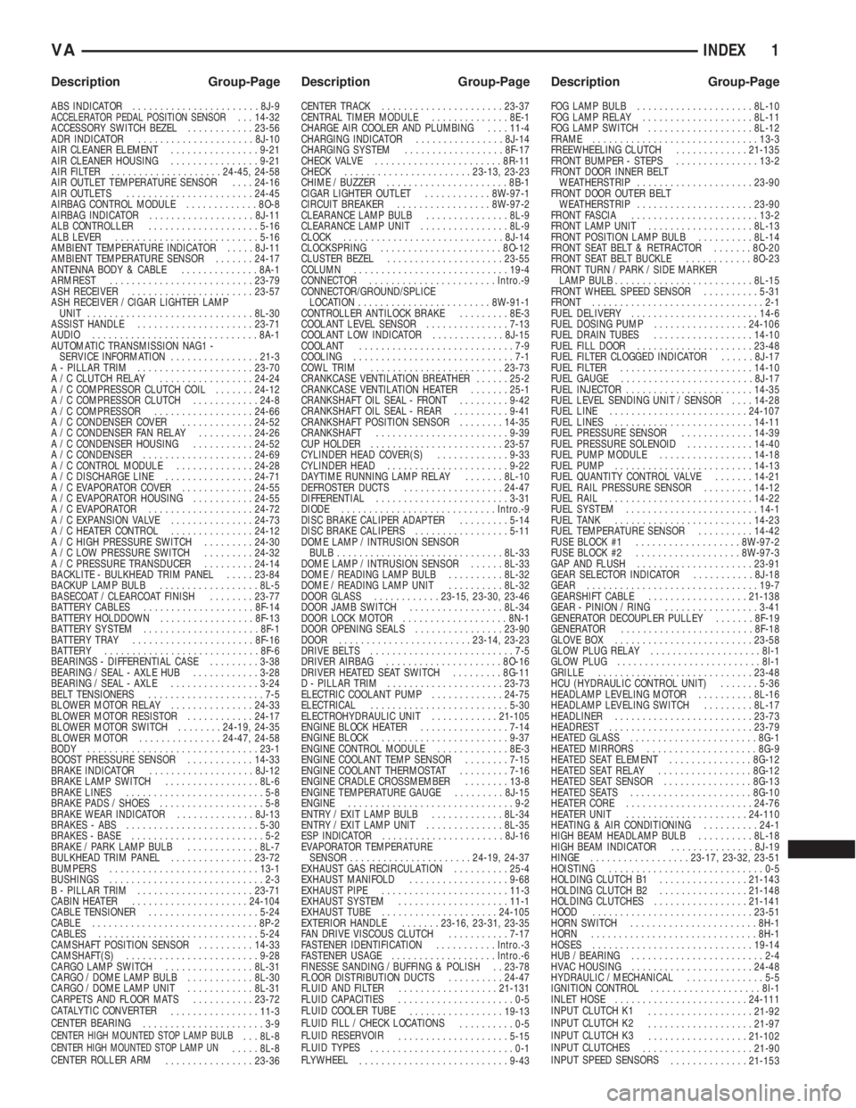
INDEX
ABS INDICATOR.......................8J-9ACCELERATOR PEDAL POSITION SENSOR. . . 14-32
ACCESSORY SWITCH BEZEL............23-56
ADR INDICATOR.....................8J-10
AIR CLEANER ELEMENT................9-21
AIR CLEANER HOUSING................9-21
AIR FILTER ....................24-45, 24-58
AIR OUTLET TEMPERATURE SENSOR....24-16
AIR OUTLETS.......................24-45
AIRBAG CONTROL MODULE.............8O-8
AIRBAG INDICATOR...................8J-11
ALB CONTROLLER....................5-16
ALB LEVER..........................5-16
AMBIENT TEMPERATURE INDICATOR.....8J-11
AMBIENT TEMPERATURE SENSOR.......24-17
ANTENNA BODY & CABLE..............8A-1
ARMREST..........................23-79
ASH RECEIVER......................23-57
ASH RECEIVER / CIGAR LIGHTER LAMP
UNIT..............................8L-30
ASSIST HANDLE.....................23-71
AUDIO..............................8A-1
AUTOMATIC TRANSMISSION NAG1 -
SERVICE INFORMATION................21-3
A - PILLAR TRIM.....................23-70
A / C CLUTCH RELAY.................24-24
A / C COMPRESSOR CLUTCH COIL.......24-12
A / C COMPRESSOR CLUTCH............24-8
A / C COMPRESSOR..................24-66
A / C CONDENSER COVER.............24-52
A / C CONDENSER FAN RELAY..........24-26
A / C CONDENSER HOUSING...........24-52
A / C CONDENSER....................24-69
A / C CONTROL MODULE..............24-28
A / C DISCHARGE LINE................24-71
A / C EVAPORATOR COVER.............24-55
A / C EVAPORATOR HOUSING...........24-55
A / C EVAPORATOR...................24-72
A / C EXPANSION VALVE...............24-73
A / C HEATER CONTROL...............24-12
A / C HIGH PRESSURE SWITCH.........24-30
A / C LOW PRESSURE SWITCH.........24-32
A / C PRESSURE TRANSDUCER.........24-14
BACKLITE - BULKHEAD TRIM PANEL.....23-84
BACKUP LAMP BULB..................8L-5
BASECOAT / CLEARCOAT FINISH........23-77
BATTERY CABLES....................8F-14
BATTERY HOLDDOWN.................8F-13
BATTERY SYSTEM.....................8F-1
BATTERY TRAY......................8F-16
BATTERY............................8F-6
BEARINGS - DIFFERENTIAL CASE.........3-38
BEARING / SEAL - AXLE HUB............3-28
BEARING / SEAL - AXLE................3-24
BELT TENSIONERS.....................7-5
BLOWER MOTOR RELAY...............24-33
BLOWER MOTOR RESISTOR............24-17
BLOWER MOTOR SWITCH........24-19, 24-35
BLOWER MOTOR...............24-47, 24-58
BODY...............................23-1
BOOST PRESSURE SENSOR............14-33
BRAKE INDICATOR...................8J-12
BRAKE LAMP SWITCH.................8L-6
BRAKE LINES.........................5-8
BRAKE PADS / SHOES...................5-8
BRAKE WEAR INDICATOR..............8J-13
BRAKES - ABS........................5-30
BRAKES - BASE........................5-2
BRAKE / PARK LAMP BULB.............8L-7
BULKHEAD TRIM PANEL...............23-72
BUMPERS...........................13-1
BUSHINGS............................2-3
B - PILLAR TRIM.....................23-71
CABIN HEATER.....................24-104
CABLE TENSIONER....................5-24
CABLE..............................8P-2
CABLES.............................5-24
CAMSHAFT POSITION SENSOR..........14-33
CAMSHAFT(S)........................9-28
CARGO LAMP SWITCH................8L-31
CARGO / DOME LAMP BULB............8L-30
CARGO / DOME LAMP UNIT............8L-31
CARPETS AND FLOOR MATS...........23-72
CATALYTIC CONVERTER
................11-3
CENTER BEARING
......................3-9
CENTER HIGH MOUNTED STOP LAMP BULB. . . 8L-8CENTER HIGH MOUNTED STOP LAMP UN.....8L-8
CENTER ROLLER ARM
................23-36CENTER TRACK......................23-37
CENTRAL TIMER MODULE..............8E-1
CHARGE AIR COOLER AND PLUMBING....11-4
CHARGING INDICATOR................8J-14
CHARGING SYSTEM..................8F-17
CHECK VALVE.......................8R-11
CHECK.......................23-13, 23-23
CHIME / BUZZER......................8B-1
CIGAR LIGHTER OUTLET............8W-97-1
CIRCUIT BREAKER.................8W-97-2
CLEARANCE LAMP BULB...............8L-9
CLEARANCE LAMP UNIT................8L-9
CLOCK.............................8J-14
CLOCKSPRING......................8O-12
CLUSTER BEZEL.....................23-55
COLUMN............................19-4
CONNECTOR.......................Intro.-9
CONNECTOR/GROUND/SPLICE
LOCATION........................8W-91-1
CONTROLLER ANTILOCK BRAKE.........8E-3
COOLANT LEVEL SENSOR...............7-13
COOLANT LOW INDICATOR.............8J-15
COOLANT............................7-9
COOLING.............................7-1
COWL TRIM........................23-73
CRANKCASE VENTILATION BREATHER......25-2
CRANKCASE VENTILATION HEATER.......25-1
CRANKSHAFT OIL SEAL - FRONT.........9-42
CRANKSHAFT OIL SEAL - REAR..........9-41
CRANKSHAFT POSITION SENSOR........14-35
CRANKSHAFT........................9-39
CUP HOLDER........................23-57
CYLINDER HEAD COVER(S).............9-33
CYLINDER HEAD......................9-22
DAYTIME RUNNING LAMP RELAY.......8L-10
DEFROSTER DUCTS..................24-47
DIFFERENTIAL........................3-31
DIODE............................Intro.-9
DISC BRAKE CALIPER ADAPTER.........5-14
DISC BRAKE CALIPERS.................5-11
DOME LAMP / INTRUSION SENSOR
BULB..............................8L-33
DOME LAMP / INTRUSION SENSOR......8L-33
DOME / READING LAMP BULB..........8L-32
DOME / READING LAMP UNIT..........8L-32
DOOR GLASS............23-15, 23-30, 23-46
DOOR JAMB SWITCH.................8L-34
DOOR LOCK MOTOR...................8N-1
DOOR OPENING SEALS................23-90
DOOR........................23-14, 23-23
DRIVE BELTS..........................7-5
DRIVER AIRBAG.....................8O-16
DRIVER HEATED SEAT SWITCH.........8G-11
D - PILLAR TRIM.....................23-73
ELECTRIC COOLANT PUMP.............24-75
ELECTRICAL.........................5-30
ELECTROHYDRAULIC UNIT............21-105
ENGINE BLOCK HEATER................7-14
ENGINE BLOCK.......................9-37
ENGINE CONTROL MODULE.............8E-3
ENGINE COOLANT TEMP SENSOR........7-15
ENGINE COOLANT THERMOSTAT.........7-16
ENGINE CRADLE CROSSMEMBER........13-8
ENGINE TEMPERATURE GAUGE.........8J-15
ENGINE..............................9-2
ENTRY / EXIT LAMP BULB.............8L-34
ENTRY / EXIT LAMP UNIT..............8L-35
ESP INDICATOR......................8J-16
EVAPORATOR TEMPERATURE
SENSOR......................24-19, 24-37
EXHAUST GAS RECIRCULATION..........25-4
EXHAUST MANIFOLD..................9-68
EXHAUST PIPE.......................11-3
EXHAUST SYSTEM....................11-1
EXHAUST TUBE.....................24-105
EXTERIOR HANDLE.......23-16, 23-31, 23-35
FAN DRIVE VISCOUS CLUTCH...........7-17
FASTENER IDENTIFICATION...........Intro.-3
FASTENER USAGE...................Intro.-6
FINESSE SANDING / BUFFING & POLISH . . 23-78
FLOOR DISTRIBUTION DUCTS..........24-47
FLUID AND FILTER..................21-131
FLUID CAPACITIES.....................0-5
FLUID COOLER TUBE
.................19-13
FLUID FILL / CHECK LOCATIONS
..........0-5
FLUID RESERVOIR
....................5-15
FLUID TYPES
..........................0-1
FLYWHEEL
...........................9-43FOG LAMP BULB.....................8L-10
FOG LAMP RELAY....................8L-11
FOG LAMP SWITCH...................8L-12
FRAME..............................13-3
FREEWHEELING CLUTCH.............21-135
FRONT BUMPER - STEPS...............13-2
FRONT DOOR INNER BELT
WEATHERSTRIP.....................23-90
FRONT DOOR OUTER BELT
WEATHERSTRIP.....................23-90
FRONT FASCIA.......................13-2
FRONT LAMP UNIT...................8L-13
FRONT POSITION LAMP BULB..........8L-14
FRONT SEAT BELT & RETRACTOR.......8O-20
FRONT SEAT BELT BUCKLE............8O-23
FRONT TURN / PARK / SIDE MARKER
LAMP BULB.........................8L-15
FRONT WHEEL SPEED SENSOR..........5-31
FRONT...............................2-1
FUEL DELIVERY.......................14-6
FUEL DOSING PUMP.................24-106
FUEL DRAIN TUBES..................14-10
FUEL FILL DOOR.....................23-48
FUEL FILTER CLOGGED INDICATOR......8J-17
FUEL FILTER........................14-10
FUEL GAUGE........................8J-17
FUEL INJECTOR.......................14-35
FUEL LEVEL SENDING UNIT / SENSOR....14-28
FUEL LINE.........................24-107
FUEL LINES.........................14-11
FUEL PRESSURE SENSOR.............14-39
FUEL PRESSURE SOLENOID............14-40
FUEL PUMP MODULE.................14-18
FUEL PUMP.........................14-13
FUEL QUANTITY CONTROL VALVE.......14-21
FUEL RAIL PRESSURE SENSOR.........14-12
FUEL RAIL..........................14-22
FUEL SYSTEM........................14-1
FUEL TANK.........................14-23
FUEL TEMPERATURE SENSOR..........14-42
FUSE BLOCK #1...................8W-97-2
FUSE BLOCK #2...................8W-97-3
GAP AND FLUSH.....................23-91
GEAR SELECTOR INDICATOR...........8J-18
GEAR...............................19-7
GEARSHIFT CABLE..................21-138
GEAR - PINION / RING.................3-41
GENERATOR DECOUPLER PULLEY.......8F-19
GENERATOR........................8F-18
GLOVE BOX.........................23-58
GLOW PLUG RELAY....................8I-1
GLOW PLUG..........................8I-1
GRILLE............................23-48
HCU (HYDRAULIC CONTROL UNIT).......5-36
HEADLAMP LEVELING MOTOR..........8L-16
HEADLAMP LEVELING SWITCH.........8L-17
HEADLINER.........................23-73
HEADREST..........................23-79
HEATED GLASS.......................8G-1
HEATED MIRRORS....................8G-9
HEATED SEAT ELEMENT...............8G-12
HEATED SEAT RELAY.................8G-12
HEATED SEAT SENSOR................8G-13
HEATED SEATS ......................8G-10
HEATER CORE.......................24-76
HEATER UNIT......................24-110
HEATING & AIR CONDITIONING..........24-1
HIGH BEAM HEADLAMP BULB..........8L-18
HIGH BEAM INDICATOR...............8J-19
HINGE..................23-17, 23-32, 23-51
HOISTING............................0-5
HOLDING CLUTCH B1................21-143
HOLDING CLUTCH B2................21-148
HOLDING CLUTCHES.................21-141
HOOD.............................23-51
HORN SWITCH.......................8H-1
HORN..............................8H-1
HOSES.............................19-14
HUB / BEARING........................2-4
HVAC HOUSING......................24-48
HYDRAULIC / MECHANICAL..............5-5
IGNITION CONTROL....................8I-1
INLET HOSE........................24-111
INPUT CLUTCH K1
...................21-92
INPUT CLUTCH K2
...................21-97
INPUT CLUTCH K3
..................21-102
INPUT CLUTCHES
....................21-90
INPUT SPEED SENSORS
..............21-153
VAINDEX 1
Description Group-Page Description Group-Page Description Group-Page
Page 2171 of 2305

information available at the time of publication.
The right is reserved to make changes at any time
without notice.
4.2 SAFETY
4.2.1 TECHNICIAN SAFETY INFORMATION
WARNING: ENGINES PRODUCE CARBON
MONOXIDE THAT IS ODORLESS, CAUSES
SLOWER REACTION TIME, AND CAN LEAD
TO SERIOUS INJURY. WHEN THE ENGINE IS
OPERATING KEEP SERVICE AREAS WELL
VENTILATED OR ATTACH THE VEHICLE
EXHAUST SYSTEM TO THE SHOP EXHAUST
REMOVAL SYSTEM.
Set the parking brake and block the wheels before
testing or repairing the vehicle. If is especially
important to block the wheels on front-wheel drive
vehicles: the parking brake does not hold the drive
wheels.
Some operations in this manual require that
hydraulic tubes, hoses, and fittings, disconnected
for inspection or testing purposes. These systems,
when fully charged, contain fluid at high pressure.
Before disconnecting any hydraulic tubes, hoses,
and fittings, be sure that the system is fully depres-
surized.
When servicing a vehicle, always wear eye pro-
tection, and remove any metal jewelry such as
watchbands or bracelets that might make an inad-
vertent electrical contact.
When diagnosing a Transmission system prob-
lem, it is important to follow approved procedures
where applicable. These procedures can be found in
the service information. Following these procedures
is very important to the safety of individuals per-
forming diagnostic tests.
4.2.2 VEHICLE PREPARATION FOR
TESTING
Make sure the vehicle being tested has a fully
charged battery. If it does not, false diagnostic
DTC's or error messages may occur. It is extremely
important that accurate shift lever position data is
available to the TCM. The accuracy of any DTC
found in memory is doubtful unless the Shift Lever
Test, performed on the DRBIIItScan Tool, passes
without failure.
4.2.3 SERVICING SUB-ASSEMBLIES
Some components of the Transmission system are
intended to be serviced in assembly only. Attempt-
ing to remove or repair certain system sub-
components may result in personal injury and/orimproper system operation. Only those components
with approved repair and installation procedures in
the service information should be serviced.
4.2.4 DRBIIITSAFETY INFORMATION
WARNING: EXCEEDING THE LIMITS OF THE
DRBIIITMULTIMETER IS DANGEROUS. IT
CAN EXPOSE YOU TO SERIOUS OR
POSSIBLY FATAL INJURY. CAREFULLY
READ AND UNDERSTAND THE CAUTIONS
AND THE SPECIFICATION LIMITS.
²Follow the vehicle manufacturer's service speci-
fications at all times.
²Do not use the DRBIIItif it has been damaged.
²Do not use the test leads if the insulation is
damaged or if metal is exposed.
²To avoid electrical shock, do not touch the test
leads, tips or the circuit being tested.
²Choose the proper range and function for the
measurement. Do not try voltage or current mea-
surements that may exceed the rated capacity.
²Do not exceed the limits shown in the table.
FUNCTION INPUT LIMIT
Volts 0-500 volts peak AC
0-500 volts DC
Ohms (resistance)* 0-1.12 megohms
Frequency measured
Frequency generated0-10 khz
Temperature -58-1100ÉF
-50-600C
*Ohms cannot be measured if voltage is present.
Ohms can be measured only in a non-powered
circuit.
²Voltage between any terminal and ground must
not exceed 500v DC or 500v peak AC.
²Use caution when measured voltage above 25v
DC or 25v AC.
²The circuit being tested must be protected by a
10A fuse or circuit breaker.
²Use the low current shunt to measure circuits up
to 10A. Use the high current clamp to measure
circuits exceeding 10A.
²When testing for the presence of voltage or cur-
rent, make sure the meter is functioning cor-
rectly. Take a reading of a known voltage or
current before accepting a zero reading.
²When measuring current, connect the meter in
series with the load.
6
GENERAL INFORMATION
Page 2172 of 2305
²Disconnect the live test lead before disconnecting
the common test lead.
²When using the meter function, keep the
DRBIIItaway from spark plug or coil wires to
avoid measuring error from outside interference.
4.3 WARNINGS
4.3.1 VEHICLE DAMAGE WARNINGS
Before disconnecting any control module, make
sure the ignition is9lock9position. Failure to do so
could damage the module.
When testing voltage or continuity at any control
module, use the terminal side (not the wire end) of
the connector. Do not probe a wire through the
insulation: this will damage the wire and eventu-
ally cause the wire to fail because of corrosion.
Be careful when performing electrical tests so as
to prevent accidental shorting of terminals. Such
mistakes can damage fuses or components. Also, a
second DTC could be set, making diagnosis of the
original problem more difficult.
When replacing a blown fuse, it is important to
use only a fuse having the correct amperage rating.
The use of a fuse with a rating other than indicated
may result in a dangerous electrical system over-
load. If a properly rated fuse continues to blow, it
indicates a problem in the circuit that must be
corrected.
4.3.2 ROAD TESTING A COMPLAINT
VEHICLE
Some complaints will require a test drive as part
of the repair verification procedure. The purpose of
the test drive is to try to duplicate the diagnostic
DTC or symptom condition.
CAUTION: Before road testing a vehicle, be
sure that all components are reassembled.
During the test drive, do not try to read
DRBIIITscreen while in motion. Do not hang
the DRBIIITfrom the rear view mirror or
operate it yourself. Have an assistant
available to operate the DRBIIIT.
Road testing is an essential step in the diagnostic
process that must not be overlooked. Along with the
diagnostic information obtained from the DRBIIIt
Scan Tool and the original customer concern, the
road test helps verify the problem was current and
any repairs performed, fixed the vehicle correctly.
Always operate and observe the vehicle under ac-
tual driving conditions.
Just as important as the road test is, there are
preliminary inspections that should be performed
prior to the road test. Always check the fluid leveland condition before taking the vehicle on a road
test. Determine if the incorrect fluid is being used,
improper fluid will result in erratic transmission
operation.
Some of the conditions of incorrect fluid level are as
follows:
²Delayed engagement
²Poor shifting or erratic shifting
²Excessive noise
²Overheating
The next step is to verify that the shift linkage is
correctly adjusted. If the shift linkage is incorrectly
adjusted, a number of complaints can result.
The TCM monitors the Shift Lever Position (SLP)
continuously. If the linkage is incorrectly adjusted,
the TCM will sense a shift lever position that is not
correct for the gear chosen by the driver. This may
cause a DTC to be set.
The following complaints may also be the result of
an incorrectly adjusted or worn linkage:
²Delayed clutch engagement
²Erratic shifts
²Vehicle will drive in neutral
²Engine will not crank in park or neutral
²Gear shift linkage will be able to be shifted
without the key in the ignition
²Not able to remove the ignition key in park
²Parking pawl will not engage properly
The shift linkage should also be adjusted when
replacing the Transmission, repairing the valve
body, or when repairing any component between the
shift lever and the Transmission.
Some questions to ask yourself when performing
the road test are as follows:
²Is the complaint or concern what you think the
problem is, based on the drivers description of the
problem?
²Is the Transmission operating normally, or is
there a real problem?
²When does the problem occur?
²Is the problem only in one gear range?
²What temperature does the problem occur?
²Does the vehicle have to sit over night for the
problem to occur?
²Does the transmission go into Limp-in mode?
4.4.4 BULLETINS AND RECALLS
Always perform all Safety Recalls and Technical
Service Bulletins that are applicable to the prob-
lem.
7
GENERAL INFORMATION
Page 2181 of 2305
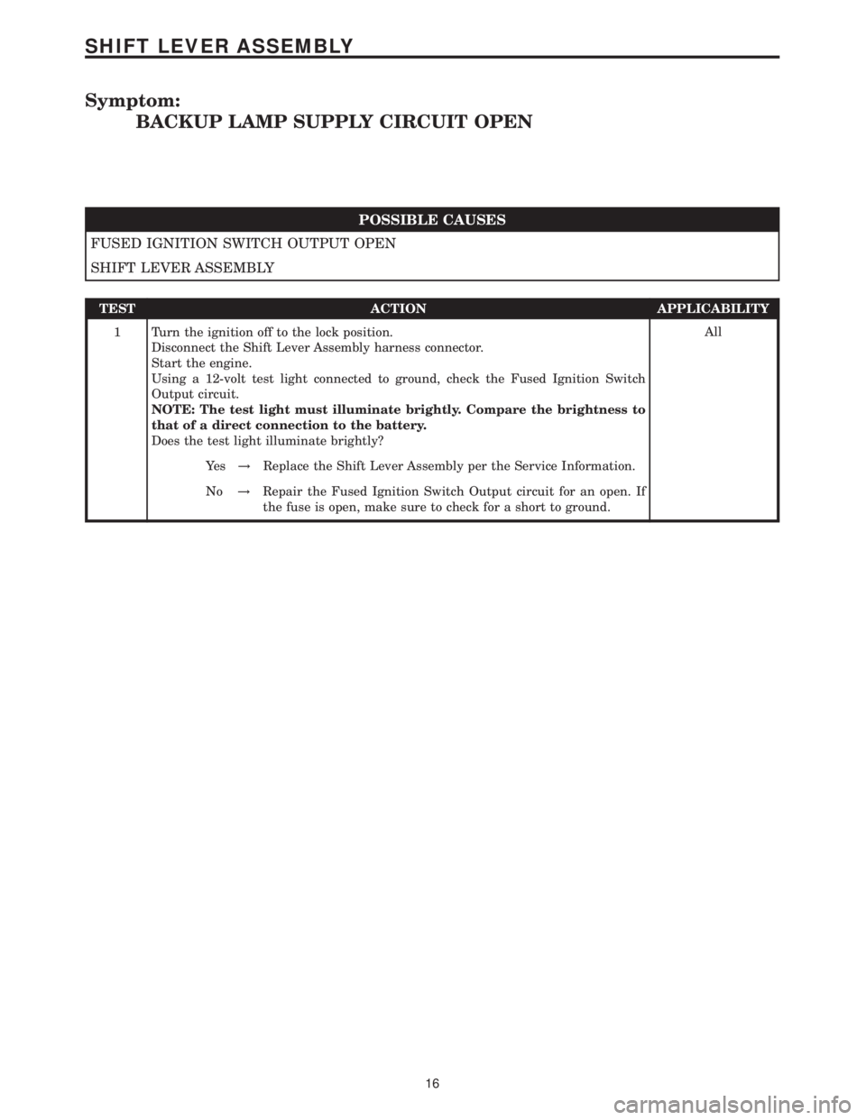
Symptom:
BACKUP LAMP SUPPLY CIRCUIT OPEN
POSSIBLE CAUSES
FUSED IGNITION SWITCH OUTPUT OPEN
SHIFT LEVER ASSEMBLY
TEST ACTION APPLICABILITY
1 Turn the ignition off to the lock position.
Disconnect the Shift Lever Assembly harness connector.
Start the engine.
Using a 12-volt test light connected to ground, check the Fused Ignition Switch
Output circuit.
NOTE: The test light must illuminate brightly. Compare the brightness to
that of a direct connection to the battery.
Does the test light illuminate brightly?All
Ye s!Replace the Shift Lever Assembly per the Service Information.
No!Repair the Fused Ignition Switch Output circuit for an open. If
the fuse is open, make sure to check for a short to ground.
16
SHIFT LEVER ASSEMBLY
Page 2296 of 2305
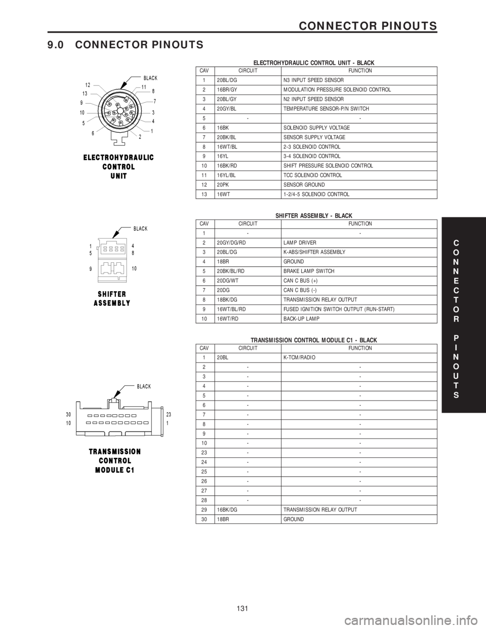
9.0 CONNECTOR PINOUTS
ELECTROHYDRAULIC CONTROL UNIT - BLACKCAV CIRCUIT FUNCTION
1 20BL/DG N3 INPUT SPEED SENSOR
2 16BR/GY MODULATION PRESSURE SOLENOID CONTROL
3 20BL/GY N2 INPUT SPEED SENSOR
4 20GY/BL TEMPERATURE SENSOR-P/N SWITCH
5- -
6 16BK SOLENOID SUPPLY VOLTAGE
7 20BK/BL SENSOR SUPPLY VOLTAGE
8 16WT/BL 2-3 SOLENOID CONTROL
9 16YL 3-4 SOLENOID CONTROL
10 16BK/RD SHIFT PRESSURE SOLENOID CONTROL
11 16YL/BL TCC SOLENOID CONTROL
12 20PK SENSOR GROUND
13 16WT 1-2/4-5 SOLENOID CONTROL
SHIFTER ASSEMBLY - BLACKCAV CIRCUIT FUNCTION
1- -
2 20GY/DG/RD LAMP DRIVER
3 20BL/DG K-ABS/SHIFTER ASSEMBLY
4 18BR GROUND
5 20BK/BL/RD BRAKE LAMP SWITCH
6 20DG/WT CAN C BUS (+)
7 20DG CAN C BUS (-)
8 18BK/DG TRANSMISSION RELAY OUTPUT
9 16WT/BL/RD FUSED IGNITION SWITCH OUTPUT (RUN-START)
10 16WT/RD BACK-UP LAMP
TRANSMISSION CONTROL MODULE C1 - BLACKCAV CIRCUIT FUNCTION
1 20BL K-TCM/RADIO
2- -
3- -
4- -
5- -
6- -
7- -
8- -
9- -
10 - -
23 - -
24 - -
25 - -
26 - -
27 - -
28 - -
29 16BK/DG TRANSMISSION RELAY OUTPUT
30 18BR GROUND
C
O
N
N
E
C
T
O
R
P
I
N
O
U
T
S
131
CONNECTOR PINOUTS
Page 2298 of 2305
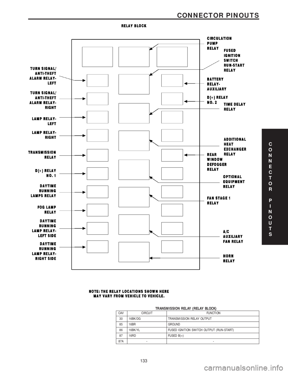
TRANSMISSION RELAY (RELAY BLOCK)CAV CIRCUIT FUNCTION
30 16BK/DG TRANSMISSION RELAY OUTPUT
85 16BR GROUND
86 16BK/YL FUSED IGNITION SWITCH OUTPUT (RUN-START)
87 16RD FUSED B(+)
87A - -
C
O
N
N
E
C
T
O
R
P
I
N
O
U
T
S
133
CONNECTOR PINOUTS