2006 MERCEDES-BENZ SPRINTER fuse
[x] Cancel search: fusePage 970 of 2305

MULTI - FUNCTION SWITCH
REMOVAL
WARNING: To avoid personal injury or death, on
vehicles equipped with airbags, disable the supple-
mental restraint system before attempting any
steering wheel, steering column, airbag, seat belt
tensioner, or instrument panel component diagno-
sis or service. Disconnect and isolate the battery
negative (ground) cable, then wait two minutes for
the system capacitor to discharge before perform-
ing further diagnosis or service. This is the only
sure way to disable the supplemental restraint sys-
tem. Failure to take the proper precautions could
result in accidental airbag deployment.
(1) Disconnect and isolate the battery negative
cable.
(2) Remove the fuse block from the underside of
the steering column. (Refer to 8 - ELECTRICAL/
POWER DISTRIBUTION/FUSE BLOCK -
REMOVAL).
(3) Remove the clockspring from the steering col-
umn. (Refer to 8 - ELECTRICAL/RESTRAINTS/
CLOCKSPRING - REMOVAL).
(4) If the vehicle is so equipped, remove the steer-
ing angle sensor from the steering column. (Refer to
5 - BRAKES/ELECTRICAL/STEERING ANGLE
SENSOR - REMOVAL).
(5) Remove the two screws that secure the upper
shroud to the top of the multi-function switch (Fig.
37).
(6) Remove the upper shroud from the top of the
multi-function switch.
(7) Remove the two screws that secure the multi-
function switch to the steering column.(8) Remove the multi-function switch from the
steering column.
(9) Remove the speed control switch from the back
of the multi-function switch. (Refer to 8 - ELECTRI-
CAL/SPEED CONTROL/SWITCH - REMOVAL).
INSTALLATION
WARNING: To avoid personal injury or death, on
vehicles equipped with airbags, disable the supple-
mental restraint system before attempting any
steering wheel, steering column, airbag, seat belt
tensioner, or instrument panel component diagno-
sis or service. Disconnect and isolate the battery
negative (ground) cable, then wait two minutes for
the system capacitor to discharge before perform-
ing further diagnosis or service. This is the only
sure way to disable the supplemental restraint sys-
tem. Failure to take the proper precautions could
result in accidental airbag deployment.
(1) Reinstall the speed control switch onto the
back of the multi-function switch. (Refer to 8 - ELEC-
TRICAL/SPEED CONTROL/SWITCH - INSTALLA-
TION).
(2) Position the multi-function switch onto the
steering column (Fig. 37).
(3) Install and tighten the two screws that secure
the multi-function switch to the steering column.
(4) Position the upper shroud onto the top of the
multi-function switch.
(5) Install and tighten the two screws that secure
the upper shroud to the top of the multi-function
switch.
(6) If the vehicle is so equipped, reinstall the steer-
ing angle sensor onto the steering column. (Refer to 5
- BRAKES/ELECTRICAL/STEERING ANGLE SEN-
SOR - INSTALLATION).
(7) Reinstall the clockspring onto the steering col-
umn. (Refer to 8 - ELECTRICAL/RESTRAINTS/
CLOCKSPRING - INSTALLATION).
(8) Reinstall the fuse block onto the underside of
the steering column. (Refer to 8 - ELECTRICAL/
POWER DISTRIBUTION/FUSE BLOCK - INSTAL-
LATION).
(9) Reconnect the battery negative cable.
PARK BRAKE SWITCH
REMOVAL
(1) Remove the trim cover from the park brake
lever (Fig. 38). (Refer to 5 - BRAKES/PARKING
BRAKE/LEVER - REMOVAL).
Fig. 37 Multi-Function Switch Remove/Install
1 - SCREW (2)
2 - UPPER SHROUD
3 - SWITCH
4 - SCREW (2)
VALAMPS/LIGHTING - EXTERIOR 8L - 21
Page 975 of 2305
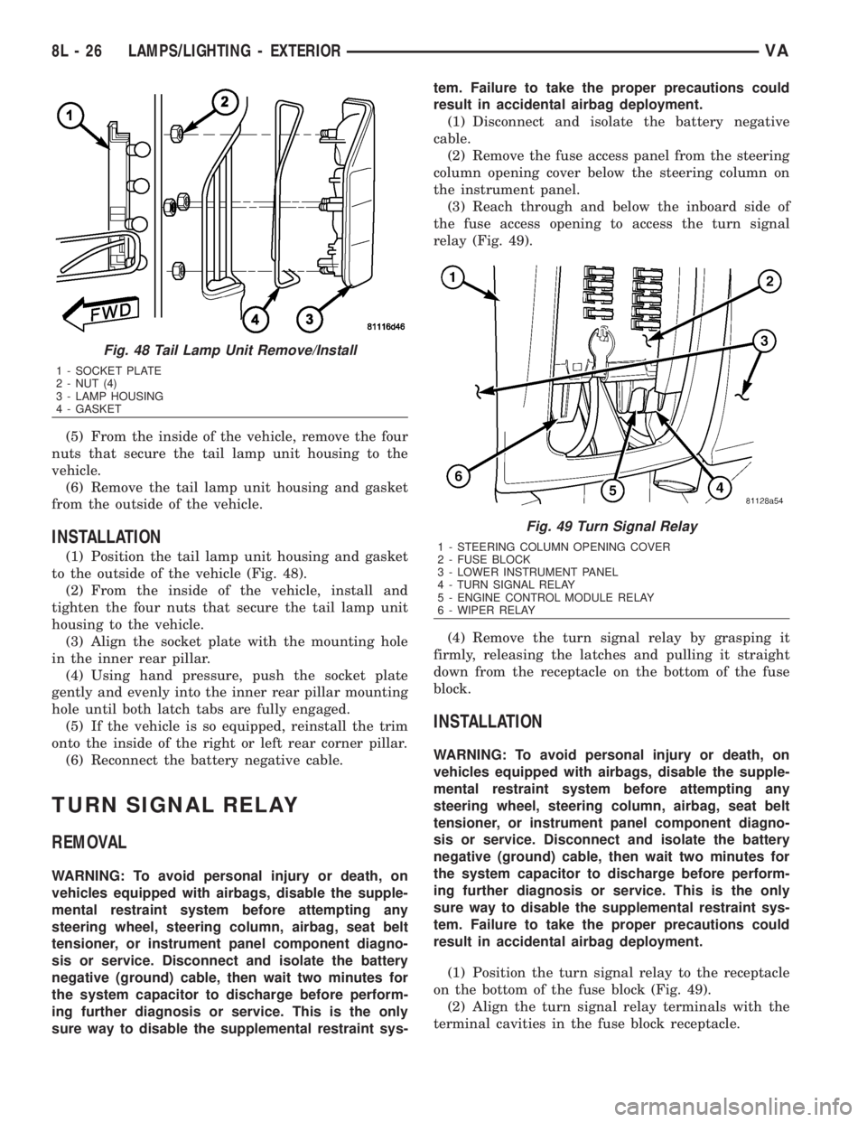
(5) From the inside of the vehicle, remove the four
nuts that secure the tail lamp unit housing to the
vehicle.
(6) Remove the tail lamp unit housing and gasket
from the outside of the vehicle.
INSTALLATION
(1) Position the tail lamp unit housing and gasket
to the outside of the vehicle (Fig. 48).
(2) From the inside of the vehicle, install and
tighten the four nuts that secure the tail lamp unit
housing to the vehicle.
(3) Align the socket plate with the mounting hole
in the inner rear pillar.
(4) Using hand pressure, push the socket plate
gently and evenly into the inner rear pillar mounting
hole until both latch tabs are fully engaged.
(5) If the vehicle is so equipped, reinstall the trim
onto the inside of the right or left rear corner pillar.
(6) Reconnect the battery negative cable.
TURN SIGNAL RELAY
REMOVAL
WARNING: To avoid personal injury or death, on
vehicles equipped with airbags, disable the supple-
mental restraint system before attempting any
steering wheel, steering column, airbag, seat belt
tensioner, or instrument panel component diagno-
sis or service. Disconnect and isolate the battery
negative (ground) cable, then wait two minutes for
the system capacitor to discharge before perform-
ing further diagnosis or service. This is the only
sure way to disable the supplemental restraint sys-tem. Failure to take the proper precautions could
result in accidental airbag deployment.
(1) Disconnect and isolate the battery negative
cable.
(2) Remove the fuse access panel from the steering
column opening cover below the steering column on
the instrument panel.
(3) Reach through and below the inboard side of
the fuse access opening to access the turn signal
relay (Fig. 49).
(4) Remove the turn signal relay by grasping it
firmly, releasing the latches and pulling it straight
down from the receptacle on the bottom of the fuse
block.
INSTALLATION
WARNING: To avoid personal injury or death, on
vehicles equipped with airbags, disable the supple-
mental restraint system before attempting any
steering wheel, steering column, airbag, seat belt
tensioner, or instrument panel component diagno-
sis or service. Disconnect and isolate the battery
negative (ground) cable, then wait two minutes for
the system capacitor to discharge before perform-
ing further diagnosis or service. This is the only
sure way to disable the supplemental restraint sys-
tem. Failure to take the proper precautions could
result in accidental airbag deployment.
(1) Position the turn signal relay to the receptacle
on the bottom of the fuse block (Fig. 49).
(2) Align the turn signal relay terminals with the
terminal cavities in the fuse block receptacle.
Fig. 48 Tail Lamp Unit Remove/Install
1 - SOCKET PLATE
2 - NUT (4)
3 - LAMP HOUSING
4 - GASKET
Fig. 49 Turn Signal Relay
1 - STEERING COLUMN OPENING COVER
2 - FUSE BLOCK
3 - LOWER INSTRUMENT PANEL
4 - TURN SIGNAL RELAY
5 - ENGINE CONTROL MODULE RELAY
6 - WIPER RELAY
8L - 26 LAMPS/LIGHTING - EXTERIORVA
Page 976 of 2305

(3) Push firmly and evenly on the top of the turn
signal relay until the terminals are fully seated in
the terminal cavities in the receptacle of the fuse
block and both latches are fully engaged.
(4) Reinstall the fuse access panel onto the steer-
ing column opening cover below the steering column
on the instrument panel.
(5) Reconnect the battery negative cable.
VALAMPS/LIGHTING - EXTERIOR 8L - 27
Page 978 of 2305
right rear door is standard equipment on wagon mod-
els. The sliding and rear door jamb switches are not
available for van models.
²Entry/Exit Lamp- An entry/exit lamp to illu-
minate each front and sliding side door step well is
optional equipment on wagon models.
²Time Delay Relay- Vehicles equipped with the
optional remote cargo lamp switches also have a time
delay relay located in the electrical center within the
driver side front seat riser.
Hard wired circuitry connects the interior lighting
system components to the electrical system of the
vehicle. These hard wired circuits are integral to sev-
eral wire harnesses, which are routed throughout the
vehicle and retained by many different methods.
These circuits may be connected to each other, to the
vehicle electrical system and to the interior lighting
system components through the use of a combination
of soldered splices, splice block connectors, and many
different types of wire harness terminal connectors
and insulators. Refer to the appropriate wiring infor-
mation. The wiring information includes wiring dia-
grams, proper wire and connector repair procedures,
further details on wire harness routing and reten-
tion, as well as pin-out and location views for the
various wire harness connectors, splices and grounds.
OPERATION
The interior lighting systems can be divided into
two general classifications based upon the circuit
that controls their operation: The interior lighting
circuit, or the exterior lighting circuit. The hard
wired circuits and components of the interior lighting
systems may be diagnosed and tested using conven-
tional diagnostic tools and procedures.
INTERIOR LIGHTING CIRCUIT
Depending upon the vehicle model (van or wagon)
and the selected vehicle options the interior lighting
circuit may include dome/cargo lamps located over-
head in the front and rear of the vehicle, a dome/
reading lamp located in the header area above the
windshield between the sun visors, and entry/exit
lamps located in the front and sliding side door step
wells.
WAGON MODELS
In all wagon models, the lamps in the interior
lighting circuit are provided with battery current at
all times by a fuse in the fuse block beneath the
steering column. The front, side, and rear door jamb
switches control a ground path for each of these
lamps, except for the optional reading lamp. If the
lamp has an optional integral switch, that switch has
three separate positions. The first position provides a
ground path independent of the door jamb switches
to turn the lamp On. The second, or center position
allows the door jamb switches to control the lamp.The third position segregates that lamp from the
door jamb switch input, turning the lamp Off. In the
case of the optional dome/reading lamp, the integral
lamp switch has a fourth position which will illumi-
nate only the reading lamp bulb.
VAN MODELS
Unless a van model is equipped with an optional
remote cargo lamp switch, all of the lamps in the
interior lighting circuit operate the same way as the
wagon models except that there are only two door
jamb switches, one for each front door. If the vehicle
is equipped with an optional remote cargo lamp
switch, the lamps in the rear of the vehicle on the
interior lighting circuit are provided with battery
current by the time delay relay. The time delay relay
is a smart relay containing active electronic elements
that comprise an electronic timer logic circuit. When
the remote cargo lamp switches provide the proper
input to the time delay relay, the relay logic responds
by energizing the relay control coil. The energized
relay control coil provides battery current to all of
the lamps on the rear interior lighting circuit and to
the indicator Light-Emitting Diode (LED) units in
the remote cargo switches causing each to illuminate.
If a remote cargo lamp switch remains On for more
than about fifteen minutes, the time delay relay will
then automatically de-energize the rear interior
lighting circuits until the remote cargo lamp switch
is cycled Off and then back On.
EXTERIOR LIGHTING CIRCUIT
The exterior lighting circuit provides battery cur-
rent to the optional ash receiver/cigar lighter lamp
and to the illumination Light-Emitting Diode (LED)
unit within the remote cargo lamp switch in the
instrument panel accessory switch bezel whenever
the exterior lamps are turned On.
SPECIFICATIONS - INTERIOR LIGHTING
VALAMPS/LIGHTING - INTERIOR 8L - 29
Page 988 of 2305
POWER MIRRORS
TABLE OF CONTENTS
page page
POWER MIRRORS
DESCRIPTION..........................3
POWER MIRROR SWITCH
DIAGNOSIS AND TESTING - POWER MIRROR
SWITCH.............................3REMOVAL.............................3
INSTALLATION..........................4
POWER MIRRORS
DESCRIPTION
The power operated outside rear view mirrors
allow the driver to adjust both outside mirrors elec-
trically from the driver side front seat position by
operating a switch on the driver side front door trim
panel. The power mirrors receive a non-switched bat-
tery feed through a fuse so that the system will
remain operational, regardless of the ignition switch
position.
POWER MIRROR SWITCH
DIAGNOSIS AND TESTING - POWER MIRROR
SWITCH
(1) Disconnect and isolate the battery negative
cable.
(2) Remove power mirror switch (Refer to 8 -
ELECTRICAL/POWER MIRRORS/POWER MIRROR
SWITCH - REMOVAL).
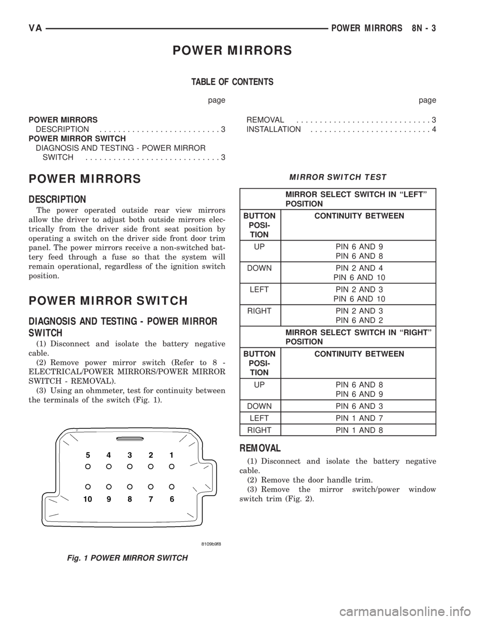
(3) Using an ohmmeter, test for continuity between
the terminals of the switch (Fig. 1).
MIRROR SWITCH TEST
MIRROR SELECT SWITCH IN ªLEFTº
POSITION
BUTTON
POSI-
TIONCONTINUITY BETWEEN
UP PIN 6 AND 9
PIN 6 AND 8
DOWN PIN 2 AND 4
PIN 6 AND 10
LEFT PIN 2 AND 3
PIN 6 AND 10
RIGHT PIN 2 AND 3
PIN 6 AND 2
MIRROR SELECT SWITCH IN ªRIGHTº
POSITION
BUTTON
POSI-
TIONCONTINUITY BETWEEN
UP PIN 6 AND 8
PIN 6 AND 9
DOWN PIN 6 AND 3
LEFT PIN 1 AND 7
RIGHT PIN 1 AND 8
REMOVAL
(1) Disconnect and isolate the battery negative
cable.
(2) Remove the door handle trim.
(3) Remove the mirror switch/power window
switch trim (Fig. 2).
Fig. 1 POWER MIRROR SWITCH
VAPOWER MIRRORS 8N - 3
Page 1000 of 2305

Communication Interface (SCI) data bus line for sup-
plemental restraint system programming or diagno-
sis and testing through the 16-way Data Link
Connector (DLC) located on the dash panel below the
driver side end of the instrument panel. A hard wired
output from the ACM is used for control of the airbag
indicator in the ElectroMechanical Instrument Clus-
ter (EMIC). (Refer to 8 - ELECTRICAL/INSTRU-
MENT CLUSTER/AIRBAG INDICATOR -
OPERATION).
The ACM microprocessor continuously monitors all
of the supplemental restraint system electrical cir-
cuits to determine the system readiness. If the ACM
detects a monitored system fault, it sets an appropri-
ate Diagnostic Trouble Code (DTC) and sends an out-
put to the EMIC to turn on the airbag indicator. The
ACM illuminates the indicator for about four seconds
each time the ignition switch is turned to the On
position as a bulb test. If the indicator remains illu-
minated for about ten seconds after the ignition
switch is turned to the On position, the ACM has
detected a non-critical fault that poses no danger to
the vehicle occupants. If the airbag indicator illumi-
nates solid (not flashing) while driving or stays on
longer than ten seconds following the bulb test, the
ACM has detected a critical fault that may cause the
airbags not to deploy when required or to deploy
when not required. An active fault only remains for
the duration of the fault, or in some cases, for the
duration of the current ignition switch cycle, while a
stored fault causes a DTC to be stored in memory by
the ACM.
The ACM receives battery current through a fused
ignition switch output circuit. The ACM receives
ground through a ground circuit and take out of the
vehicle wire harness. This take out has an eyelet ter-
minal connector secured by a nut to a ground stud on
the floor panel directly below the ACM within the
driver side seat riser. A case ground is also provided
for the ACM through a ground circuit and eyelet ter-
minal connector secured under the left rear ACM
mounting screw. These connections allow the ACM to
be operational whenever the ignition switch is in the
On position.
The ACM also contains an energy-storage capaci-
tor. When the ignition switch is in the On position,
this capacitor is continually being charged with
enough electrical energy to deploy the supplemental
restraint components for up to one second following a
battery disconnect or failure. The purpose of the
capacitor is to provide backup supplemental restraint
system protection in case there is a loss of battery
current supply to the ACM during an impact.
Two sensors are contained within the ACM, an
electronic impact sensor and a safing sensor. These
electronic sensors are accelerometers that sense the
rate of vehicle deceleration, which provide verifica-
tion of the direction and severity of an impact. Onmodels equipped with optional side curtain airbags,
the ACM also monitors inputs from two remote side
impact sensors located within the left and right front
door step wells to control deployment of the side cur-
tain airbag units.
The safing sensor is an electronic accelerometer
sensor within the ACM that provides an additional
logic input to the ACM microprocessor. The safing
sensor is used to verify the need for a supplemental
restraint deployment by detecting impact energy of a
lesser magnitude than that of the primary electronic
impact sensors, and must exceed a safing threshold
in order for the airbags to deploy. Vehicles equipped
with optional side curtain airbags feature a second
safing sensor within the ACM to provide confirma-
tion to the ACM microprocessor of side impact forces.
This second safing sensor is a bi-directional unit that
detects impact forces from either side of the vehicle.
Pre-programmed decision algorithms in the ACM
microprocessor determine when the deceleration rate
as signaled by the impact sensors and the safing sen-
sors indicate an impact that is severe enough to
require supplemental restraint system protection.
When the programmed conditions are met, the ACM
sends the proper electrical signals to deploy the front
airbags and seat belt tensioners and, if the vehicle is
so equipped, either side curtain airbag unit.
The ACM also provides a hard wired electrical
crash signal output following a supplemental
restraint deployment event. This output is used to
signal other electronic modules in the vehicle to pro-
vide their enhanced accident response features,
which include automatically disabling the engine
from running and unlocking all of the doors. How-
ever, these responses are each dependent upon the
circuits, components, and modules controlling these
features remaining intact from collateral damage
incurred during the vehicle impact.
A single ACM is used for all variations of the sup-
plemental restraint system available in this vehicle.
This ACM is programmable and in order to function
properly it must be programmed for the correct vehi-
cle supplemental restraint system equipment using
an initialization procedure. The initialization proce-
dure requires the use of a diagnostic scan tool. Refer
to the appropriate diagnostic information. The hard
wired inputs and outputs for the ACM may be diag-
nosed and tested using conventional diagnostic tools
and procedures. However, conventional diagnostic
methods will not prove conclusive in the diagnosis of
the ACM or the supplemental restraint system. The
most reliable, efficient, and accurate means to diag-
nose the ACM or the supplemental restraint system
requires the use of a diagnostic scan tool. Refer to
the appropriate diagnostic information.
VARESTRAINTS 8O - 9
Page 1006 of 2305
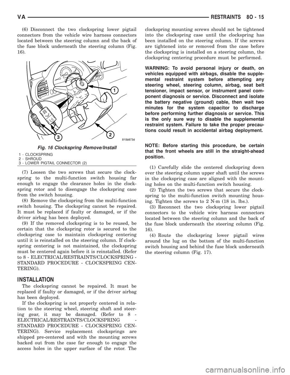
(6) Disconnect the two clockspring lower pigtail
connectors from the vehicle wire harness connectors
located between the steering column and the back of
the fuse block underneath the steering column (Fig.
16).
(7) Loosen the two screws that secure the clock-
spring to the multi-function switch housing far
enough to engage the clearance holes in the clock-
spring rotor and to disengage the clockspring case
from the switch housing.
(8) Remove the clockspring from the multi-function
switch housing. The clockspring cannot be repaired.
It must be replaced if faulty or damaged, or if the
driver airbag has been deployed.
(9) If the removed clockspring is to be reused, be
certain that the clockspring rotor is secured to the
clockspring case to maintain clockspring centering
until it is reinstalled on the steering column. If clock-
spring centering is not maintained, the clockspring
must be centered again before it is reinstalled. (Refer
to 8 - ELECTRICAL/RESTRAINTS/CLOCKSPRING -
STANDARD PROCEDURE - CLOCKSPRING CEN-
TERING).
INSTALLATION
The clockspring cannot be repaired. It must be
replaced if faulty or damaged, or if the driver airbag
has been deployed.
If the clockspring is not properly centered in rela-
tion to the steering wheel, steering shaft and steer-
ing gear, it may be damaged. (Refer to 8 -
ELECTRICAL/RESTRAINTS/CLOCKSPRING -
STANDARD PROCEDURE - CLOCKSPRING CEN-
TERING). Service replacement clocksprings are
shipped pre-centered and with the mounting screws
backed out from the case far enough to engage the
access holes in the upper surface of the rotor. Theclockspring mounting screws should not be tightened
into the clockspring case until the clockspring has
been installed on the steering column. If the screws
are tightened into or removed from the case before
the clockspring is installed on a steering column, the
clockspring centering procedure must be performed.
WARNING: To avoid personal injury or death, on
vehicles equipped with airbags, disable the supple-
mental restraint system before attempting any
steering wheel, steering column, airbag, seat belt
tensioner, impact sensor, or instrument panel com-
ponent diagnosis or service. Disconnect and isolate
the battery negative (ground) cable, then wait two
minutes for the system capacitor to discharge
before performing further diagnosis or service. This
is the only sure way to disable the supplemental
restraint system. Failure to take the proper precau-
tions could result in accidental airbag deployment.
NOTE: Before starting this procedure, be certain
that the front wheels are still in the straight-ahead
position.
(1) Carefully slide the centered clockspring down
over the steering column upper shaft until the screws
in the clockspring case are aligned with the mount-
ing holes on the multi-function switch housing.
(2) Tighten the two screws that secure the clock-
spring to the multi-function switch mounting hous-
ing. Tighten the screws to 2 N´m (18 in. lbs.).
(3) Reconnect the two clockspring lower pigtail
connectors to the vehicle wire harness connectors
located between the steering column and the back of
the fuse block underneath the steering column (Fig.
16).
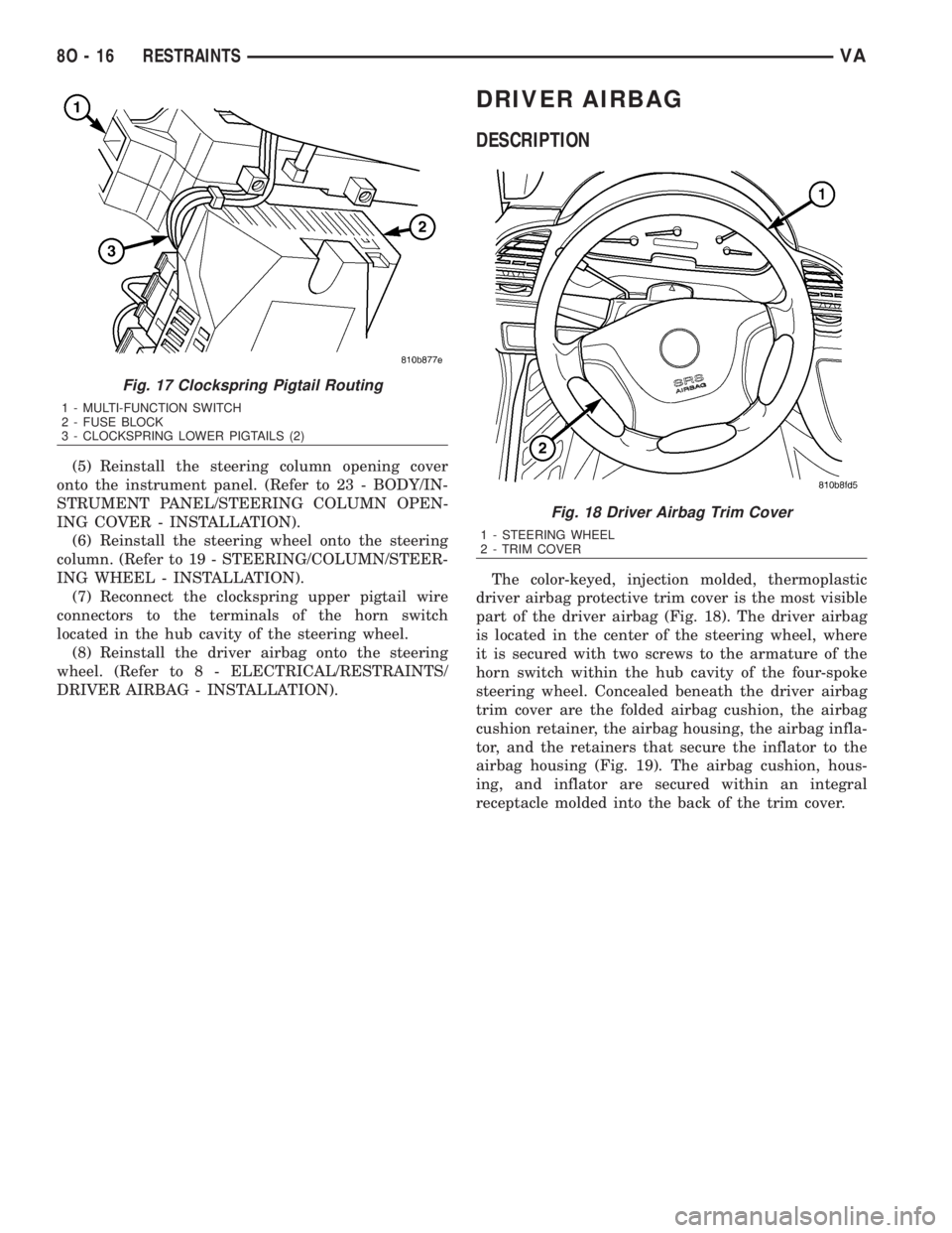
(4) Route the clockspring lower pigtail wires
around the lug on the bottom of the multi-function
switch housing and behind the fuse block underneath
the steering column (Fig. 17).
Fig. 16 Clockspring Remove/Install
1 - CLOCKSPRING
2 - SHROUD
3 - LOWER PIGTAIL CONNECTOR (2)
VARESTRAINTS 8O - 15
Page 1007 of 2305
(5) Reinstall the steering column opening cover
onto the instrument panel. (Refer to 23 - BODY/IN-
STRUMENT PANEL/STEERING COLUMN OPEN-
ING COVER - INSTALLATION).
(6) Reinstall the steering wheel onto the steering
column. (Refer to 19 - STEERING/COLUMN/STEER-
ING WHEEL - INSTALLATION).
(7) Reconnect the clockspring upper pigtail wire
connectors to the terminals of the horn switch
located in the hub cavity of the steering wheel.
(8) Reinstall the driver airbag onto the steering
wheel. (Refer to 8 - ELECTRICAL/RESTRAINTS/
DRIVER AIRBAG - INSTALLATION).
DRIVER AIRBAG
DESCRIPTION
The color-keyed, injection molded, thermoplastic
driver airbag protective trim cover is the most visible
part of the driver airbag (Fig. 18). The driver airbag
is located in the center of the steering wheel, where
it is secured with two screws to the armature of the
horn switch within the hub cavity of the four-spoke
steering wheel. Concealed beneath the driver airbag
trim cover are the folded airbag cushion, the airbag
cushion retainer, the airbag housing, the airbag infla-
tor, and the retainers that secure the inflator to the
airbag housing (Fig. 19). The airbag cushion, hous-
ing, and inflator are secured within an integral
receptacle molded into the back of the trim cover.
Fig. 17 Clockspring Pigtail Routing
1 - MULTI-FUNCTION SWITCH
2 - FUSE BLOCK
3 - CLOCKSPRING LOWER PIGTAILS (2)
Fig. 18 Driver Airbag Trim Cover
1 - STEERING WHEEL
2 - TRIM COVER
8O - 16 RESTRAINTSVA