2006 MERCEDES-BENZ SPRINTER fuse
[x] Cancel search: fusePage 1058 of 2305
RAIN SENSOR CONTROL MOD-
ULE
DESCRIPTION
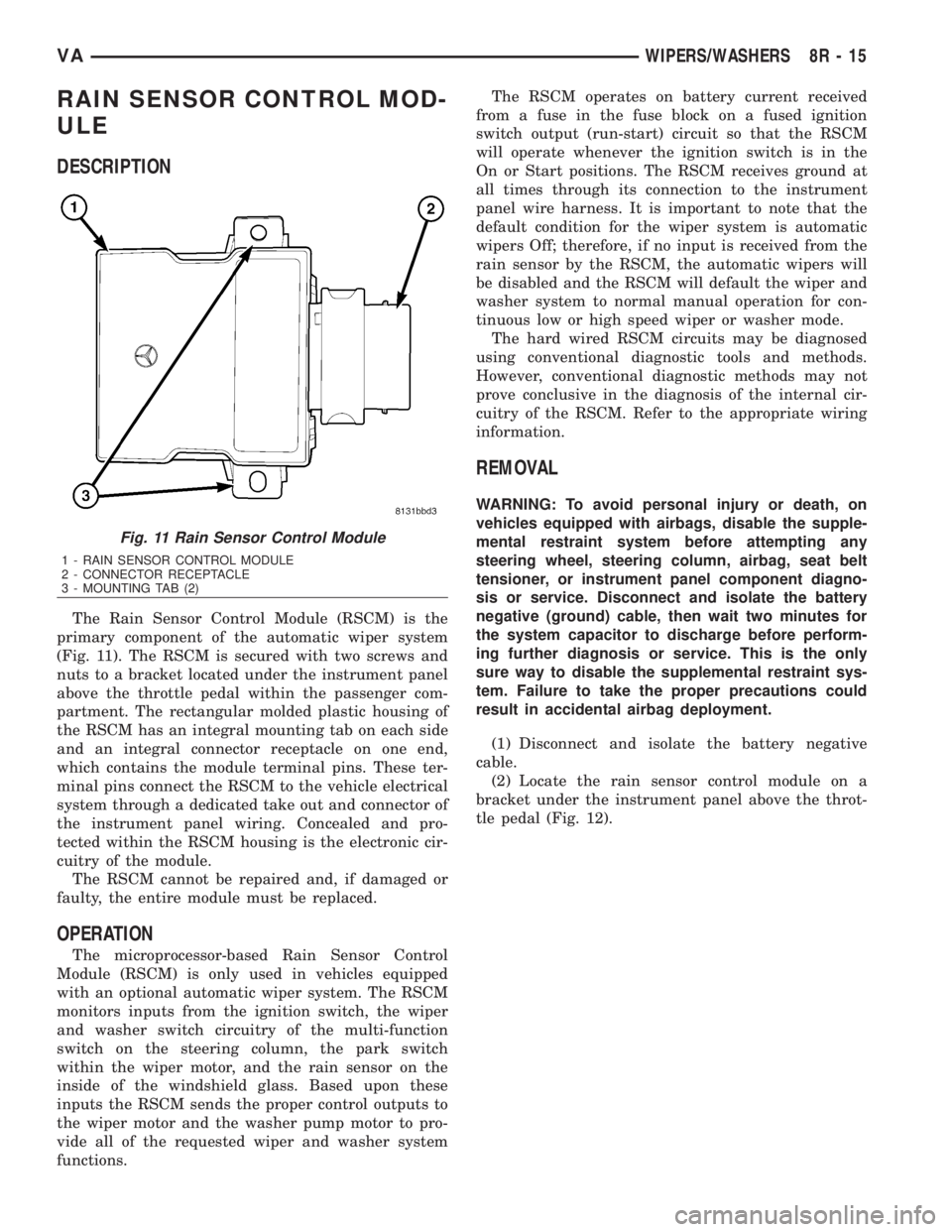
The Rain Sensor Control Module (RSCM) is the
primary component of the automatic wiper system
(Fig. 11). The RSCM is secured with two screws and
nuts to a bracket located under the instrument panel
above the throttle pedal within the passenger com-
partment. The rectangular molded plastic housing of
the RSCM has an integral mounting tab on each side
and an integral connector receptacle on one end,
which contains the module terminal pins. These ter-
minal pins connect the RSCM to the vehicle electrical
system through a dedicated take out and connector of
the instrument panel wiring. Concealed and pro-
tected within the RSCM housing is the electronic cir-
cuitry of the module.
The RSCM cannot be repaired and, if damaged or
faulty, the entire module must be replaced.
OPERATION
The microprocessor-based Rain Sensor Control
Module (RSCM) is only used in vehicles equipped
with an optional automatic wiper system. The RSCM
monitors inputs from the ignition switch, the wiper
and washer switch circuitry of the multi-function
switch on the steering column, the park switch
within the wiper motor, and the rain sensor on the
inside of the windshield glass. Based upon these
inputs the RSCM sends the proper control outputs to
the wiper motor and the washer pump motor to pro-
vide all of the requested wiper and washer system
functions.The RSCM operates on battery current received
from a fuse in the fuse block on a fused ignition
switch output (run-start) circuit so that the RSCM
will operate whenever the ignition switch is in the
On or Start positions. The RSCM receives ground at
all times through its connection to the instrument
panel wire harness. It is important to note that the
default condition for the wiper system is automatic
wipers Off; therefore, if no input is received from the
rain sensor by the RSCM, the automatic wipers will
be disabled and the RSCM will default the wiper and
washer system to normal manual operation for con-
tinuous low or high speed wiper or washer mode.
The hard wired RSCM circuits may be diagnosed
using conventional diagnostic tools and methods.
However, conventional diagnostic methods may not
prove conclusive in the diagnosis of the internal cir-
cuitry of the RSCM. Refer to the appropriate wiring
information.
REMOVAL
WARNING: To avoid personal injury or death, on
vehicles equipped with airbags, disable the supple-
mental restraint system before attempting any
steering wheel, steering column, airbag, seat belt
tensioner, or instrument panel component diagno-
sis or service. Disconnect and isolate the battery
negative (ground) cable, then wait two minutes for
the system capacitor to discharge before perform-
ing further diagnosis or service. This is the only
sure way to disable the supplemental restraint sys-
tem. Failure to take the proper precautions could
result in accidental airbag deployment.
(1) Disconnect and isolate the battery negative
cable.
(2) Locate the rain sensor control module on a
bracket under the instrument panel above the throt-
tle pedal (Fig. 12).
Fig. 11 Rain Sensor Control Module
1 - RAIN SENSOR CONTROL MODULE
2 - CONNECTOR RECEPTACLE
3 - MOUNTING TAB (2)
VAWIPERS/WASHERS 8R - 15
Page 1075 of 2305

OPERATION
The wiper motor operation is controlled by the
vehicle operator through battery current inputs
received by the wiper motor from the wiper switch
circuitry of the multi-function switch on the top of
the steering column, and from the wiper relay on the
fuse block underneath the steering column. The
wiper motor speed is controlled by current flow to
either the low speed or the high speed set of brushes.
The automatic resetting circuit breaker protects the
motor from overloads.
The park switch consists of a contact disc and
three contacts. The contact disc is mechanically fas-
tened to and rotated with a gear in the wiper motor
transmission. Two input contacts alternately close
the wiper park switch sense output circuit contact to
ground or to battery current, depending upon the
position of the wipers on the glass. This feature
allows the intermittent wipe logic circuit to monitor
the position and the cycles of the wiper motor to pro-
vide the intermittent wipe and wipe-after-wash
modes, as well as allowing the motor to complete its
current wipe cycle after the wiper system has been
turned Off and park the wiper blades in the lowest
portion of the wipe pattern.
The wiper motor may be diagnosed using conven-
tional diagnostic tools and methods.
REMOVAL
(1) Disconnect and isolate the battery negative
cable.
(2) Disconnect the vehicle wire harness connector
for the wiper motor from the motor pigtail wire con-
nector (Fig. 32).
8R - 32 WIPERS/WASHERSVA
Page 1077 of 2305
WIPER RELAY
DESCRIPTION
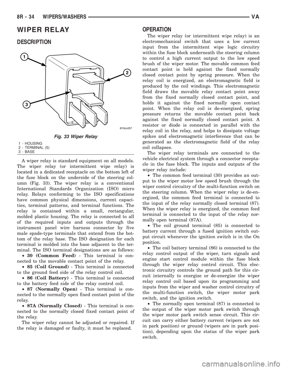
A wiper relay is standard equipment on all models.
The wiper relay (or intermittent wipe relay) is
located in a dedicated receptacle on the bottom left of
the fuse block on the underside of the steering col-
umn (Fig. 33). The wiper relay is a conventional
International Standards Organization (ISO) micro
relay. Relays conforming to the ISO specifications
have common physical dimensions, current capaci-
ties, terminal patterns, and terminal functions. The
relay is contained within a small, rectangular,
molded plastic housing. The relay is connected to all
of the required inputs and outputs through the
instrument panel wire harness connector by five
male spade-type terminals that extend from the bot-
tom of the relay base. The ISO designation for each
terminal is molded into the base adjacent to the ter-
minal. The ISO terminal designations are as follows:
²30 (Common Feed)- This terminal is con-
nected to the movable contact point of the relay.
²85 (Coil Ground)- This terminal is connected
to the ground feed side of the relay control coil.
²86 (Coil Battery)- This terminal is connected
to the battery feed side of the relay control coil.
²87 (Normally Open)- This terminal is con-
nected to the normally open fixed contact point of the
relay.
²87A (Normally Closed)- This terminal is con-
nected to the normally closed fixed contact point of
the relay.
The wiper relay cannot be adjusted or repaired. If
the relay is damaged or faulty, it must be replaced.
OPERATION
The wiper relay (or intermittent wipe relay) is an
electromechanical switch that uses a low current
input from the intermittent wipe logic circuitry
within the fuse block underneath the steering column
to control a high current output to the low speed
brush of the wiper motor. The movable common feed
contact point is held against the fixed normally
closed contact point by spring pressure. When the
relay coil is energized, an electromagnetic field is
produced by the coil windings. This electromagnetic
field draws the movable relay contact point away
from the fixed normally closed contact point, and
holds it against the fixed normally open contact
point. When the relay coil is de-energized, spring
pressure returns the movable contact point back
against the fixed normally closed contact point. A
resistor or diode is connected in parallel with the
relay coil in the relay, and helps to dissipate voltage
spikes and electromagnetic interference that can be
generated as the electromagnetic field of the relay
coil collapses.
The wiper relay terminals are connected to the
vehicle electrical system through a connector recepta-
cle in the fuse block. The inputs and outputs of the
wiper relay include:
²The common feed terminal (30) provides an out-
put to the wiper motor low speed brush through the
wiper control circuitry of the multi-function switch on
the steering column. When the wiper relay is de-en-
ergized, the common feed terminal is connected to
the input of the relay normally closed terminal (87).
When the wiper relay is energized, the common feed
terminal is connected to the input of the relay nor-
mally open terminal (87A).
²The coil ground terminal (85) is connected to
battery current through a fused ignition switch out-
put circuit whenever the ignition switch is in the On
position.
²The coil battery terminal (86) is connected to the
relay control output of the wiper, turn signals and
engine start control module within the fuse block
through the wiper relay control circuit. This elec-
tronic circuitry controls the ground path for this cir-
cuit internally to energize or de-energize the wiper
relay control coil based upon its programming and
inputs from the wiper and washer control circuitry of
the multi-function switch, the wiper motor park
switch, and the ignition switch.
²The normally open terminal (87) is connected to
the output of the wiper motor park switch through
the wiper motor park switch sense circuit. This cir-
cuit can carry either battery current (wipers are not
in park position) or ground (wipers are in park posi-
tion), depending upon the status of the wiper park
switch.
Fig. 33 Wiper Relay
1 - HOUSING
2 - TERMINAL (5)
3 - BASE
8R - 34 WIPERS/WASHERSVA
Page 1078 of 2305
²The normally closed terminal (87A) is connected
to battery current through a fused ignition switch
output circuit whenever the ignition switch is in the
On position.
The wiper relay can be diagnosed using conven-
tional diagnostic tools and methods.
REMOVAL
WARNING: To avoid personal injury or death, on
vehicles equipped with airbags, disable the supple-
mental restraint system before attempting any
steering wheel, steering column, airbag, seat belt
tensioner, or instrument panel component diagno-
sis or service. Disconnect and isolate the battery
negative (ground) cable, then wait two minutes for
the system capacitor to discharge before perform-
ing further diagnosis or service. This is the only
sure way to disable the supplemental restraint sys-
tem. Failure to take the proper precautions could
result in accidental airbag deployment.
(1) Disconnect and isolate the battery negative
cable.
(2) Remove the fuse access panel from the steering
column opening cover below the steering column on
the instrument panel.
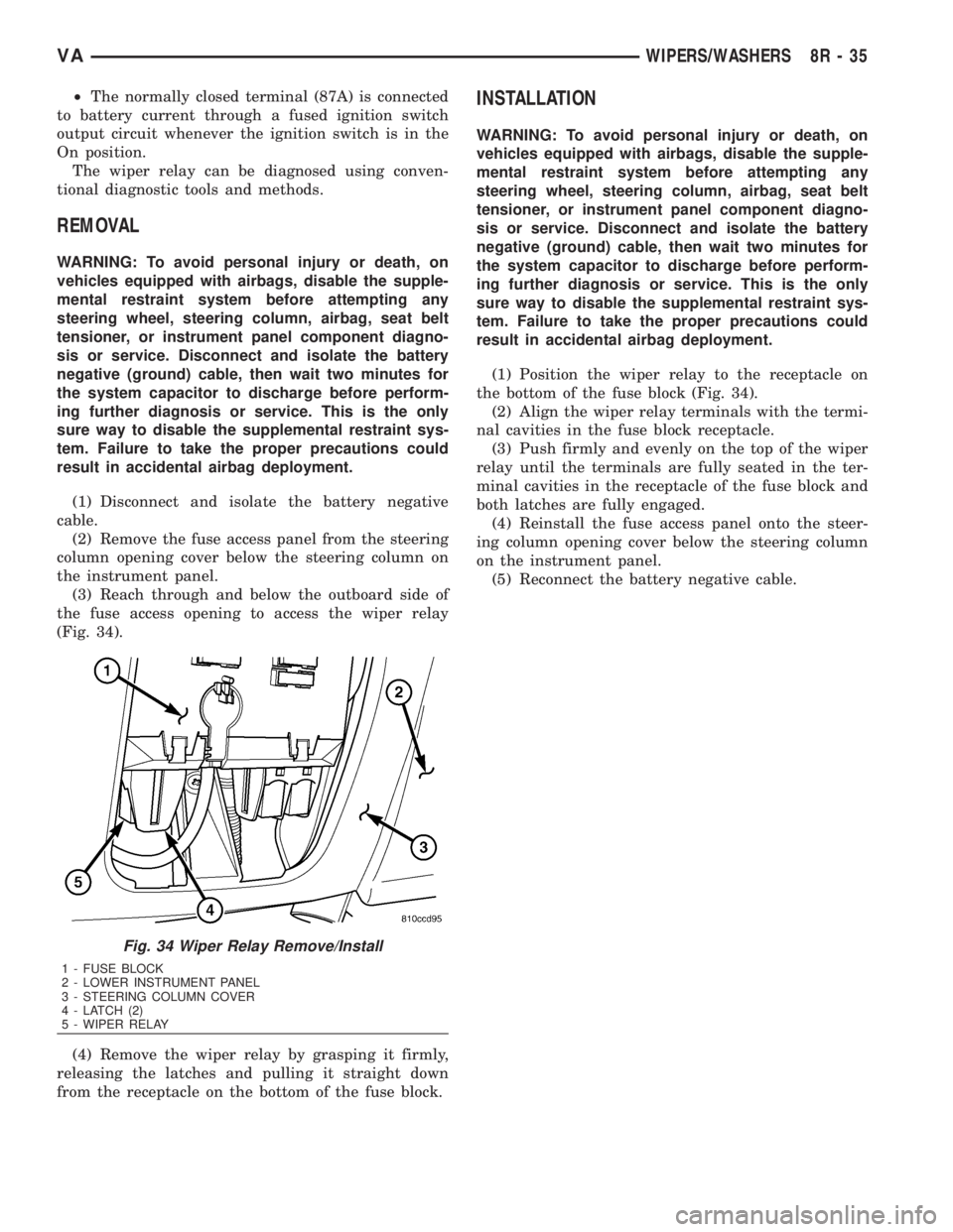
(3) Reach through and below the outboard side of
the fuse access opening to access the wiper relay
(Fig. 34).
(4) Remove the wiper relay by grasping it firmly,
releasing the latches and pulling it straight down
from the receptacle on the bottom of the fuse block.
INSTALLATION
WARNING: To avoid personal injury or death, on
vehicles equipped with airbags, disable the supple-
mental restraint system before attempting any
steering wheel, steering column, airbag, seat belt
tensioner, or instrument panel component diagno-
sis or service. Disconnect and isolate the battery
negative (ground) cable, then wait two minutes for
the system capacitor to discharge before perform-
ing further diagnosis or service. This is the only
sure way to disable the supplemental restraint sys-
tem. Failure to take the proper precautions could
result in accidental airbag deployment.
(1) Position the wiper relay to the receptacle on
the bottom of the fuse block (Fig. 34).
(2) Align the wiper relay terminals with the termi-
nal cavities in the fuse block receptacle.
(3) Push firmly and evenly on the top of the wiper
relay until the terminals are fully seated in the ter-
minal cavities in the receptacle of the fuse block and
both latches are fully engaged.
(4) Reinstall the fuse access panel onto the steer-
ing column opening cover below the steering column
on the instrument panel.
(5) Reconnect the battery negative cable.
Fig. 34 Wiper Relay Remove/Install
1 - FUSE BLOCK
2 - LOWER INSTRUMENT PANEL
3 - STEERING COLUMN COVER
4 - LATCH (2)
5 - WIPER RELAY
VAWIPERS/WASHERS 8R - 35
Page 1080 of 2305

WIRING
TABLE OF CONTENTS
page page
WIRING DIAGRAM INFORMATION....... 8W-01-1
COMPONENT INDEX.................. 8W-02-1
POWER DISTRIBUTION............... 8W-10-1
FUSE BLOCK........................ 8W-11-1
GROUND DISTRIBUTION.............. 8W-15-1
BUS COMMUNICATIONS.............. 8W-18-1
CHARGING SYSTEM.................. 8W-20-1
STARTING SYSTEM.................. 8W-21-1
FUEL/IGNITION SYSTEM.............. 8W-30-1
TRANSMISSION CONTROL SYSTEM..... 8W-31-1
VEHICLE SPEED CONTROL............ 8W-33-1
ANTILOCK BRAKES................... 8W-35-1
VEHICLE THEFT SECURITY SYSTEM..... 8W-39-1
INSTRUMENT CLUSTER............... 8W-40-1
HORN/CIGAR LIGHTER................ 8W-41-1
AIR CONDITIONING-HEATER........... 8W-42-1
AIRBAG SYSTEM.................... 8W-43-1
INTERIOR LIGHTING.................. 8W-44-1CENTRAL TIMER MODULE............. 8W-45-1
AUDIO SYSTEM..................... 8W-47-1
REAR WINDOW DEFOGGER............ 8W-48-1
FRONT LIGHTING.................... 8W-50-1
REAR LIGHTING..................... 8W-51-1
TURN SIGNALS...................... 8W-52-1
WIPERS............................ 8W-53-1
TRAILER TOW....................... 8W-54-1
NAVIGATION/TELECOMMUNICATIONS.... 8W-55-1
POWER WINDOWS................... 8W-60-1
POWER DOOR LOCKS................ 8W-61-1
POWER MIRRORS................... 8W-62-1
POWER SEATS...................... 8W-63-1
SPLICE INFORMATION................ 8W-70-1
CONNECTOR PIN-OUTS............... 8W-80-1
CONNECTOR/GROUND/SPLICE
LOCATION........................ 8W-91-1
POWER DISTRIBUTION............... 8W-97-1 VAWIRING 8W - 1
Page 1082 of 2305
8W-01 WIRING DIAGRAM INFORMATION
TABLE OF CONTENTS
page page
WIRING DIAGRAM INFORMATION
DESCRIPTION
HOW TO USE WIRING DIAGRAMS.........1
CIRCUIT INFORMATION.................5
SECTION IDENTIFICATION AND
INFORMATION........................5
CONNECTOR, GROUND, AND SPLICE
INFORMATION........................5
WARNINGS - GENERAL...................6
DIAGNOSIS AND TESTING
WIRING HARNESS.....................6
STANDARD PROCEDURE
ELECTROSTATIC DISCHARGE (ESD)
SENSITIVE DEVICES...................7
TESTING FOR VOLTAGE POTENTIAL.......7
TESTING FOR CONTINUITY..............7
TESTING FOR A SHORT TO GROUND......8TESTING COMPONENTS FOR A SHORT TO
GROUND ON A FUSE POWERING
SEVERAL LOADS......................8
TESTING FOR A VOLTAGE DROP.........8
CONNECTOR
REMOVAL.............................9
INSTALLATION..........................9
DIODE
REMOVAL.............................9
INSTALLATION..........................9
TERMINAL
REMOVAL.............................10
INSTALLATION.........................10
WIRE
STANDARD PROCEDURE
WIRE SPLICING......................10
WIRING DIAGRAM INFORMA-
TION
DESCRIPTION
HOW TO USE WIRING DIAGRAMS
DaimlerChrysler Corporation wiring diagrams are
designed to provide information regarding the vehi-
cles wiring content. In order to effectively use the
wiring diagrams to diagnose and repair
DaimlerChrysler Corporation vehicles, it is important
to understand all of their features and characteris-
tics.
Diagrams are arranged such that the power (B+)
side of the circuit is placed near the top of the page,
and the ground (B-) side of the circuit is placed near
the bottom of the page (Fig. 1).
All switches, components, and modules are shown
in the at rest position with the doors closed and the
key removed from the ignition (Fig. 2).Components are shown two ways. A solid line
around a component indicates that the component is
complete. A dashed line around the component indi-
cates that the component is being shown is not com-
plete. Incomplete components have a reference
number to indicate the page where the component is
shown complete.
It is important to realize that no attempt is made
on the diagrams to represent components and wiring
as they appear on the vehicle. For example, a short
piece of wire is treated the same as a long one. In
addition, switches and other components are shown
as simply as possible, with regard to function only.
SYMBOLS
International symbols are used throughout the wir-
ing diagrams. These symbols are consistent with
those being used around the world (Fig. 3).
VA8W-01 WIRING DIAGRAM INFORMATION 8W - 01 - 1
Page 1088 of 2305
INTERMITTENT AND POOR CONNECTIONS
Most intermittent electrical problems are caused
by faulty electrical connections or wiring. It is also
possible for a sticking component or relay to cause a
problem. Before condemning a component or wiring
assembly, check the following items.
²Connectors are fully seated
²Spread terminals, or terminal push out
²Terminals in the wiring assembly are fully
seated into the connector/component and locked into
position
²Dirt or corrosion on the terminals. Any amount
of corrosion or dirt could cause an intermittent prob-
lem
²Damaged connector/component casing exposing
the item to dirt or moisture
²Wire insulation that has rubbed through causing
a short to ground
²Some or all of the wiring strands broken inside
of the insulation
²Wiring broken inside of the insulation
TROUBLESHOOTING WIRING PROBLEMS
When troubleshooting wiring problems there are
six steps which can aid in the procedure. The steps
are listed and explained below. Always check for non-
factory items added to the vehicle before doing any
diagnosis. If the vehicle is equipped with these items,
disconnect them to verify these add-on items are not
the cause of the problem.
(1) Verify the problem.
(2) Verify any related symptoms. Do this by per-
forming operational checks on components that are
in the same circuit. Refer to the wiring diagrams.
(3) Analyze the symptoms. Use the wiring dia-
grams to determine what the circuit is doing, where
the problem most likely is occurring and where the
diagnosis will continue.
(4) Isolate the problem area.
(5) Repair the problem area.(6) Verify the proper operation. For this step,
check for proper operation of all items on the
repaired circuit. Refer to the wiring diagrams.
STANDARD PROCEDURE
ELECTROSTATIC DISCHARGE (ESD) SENSITIVE
DEVICES
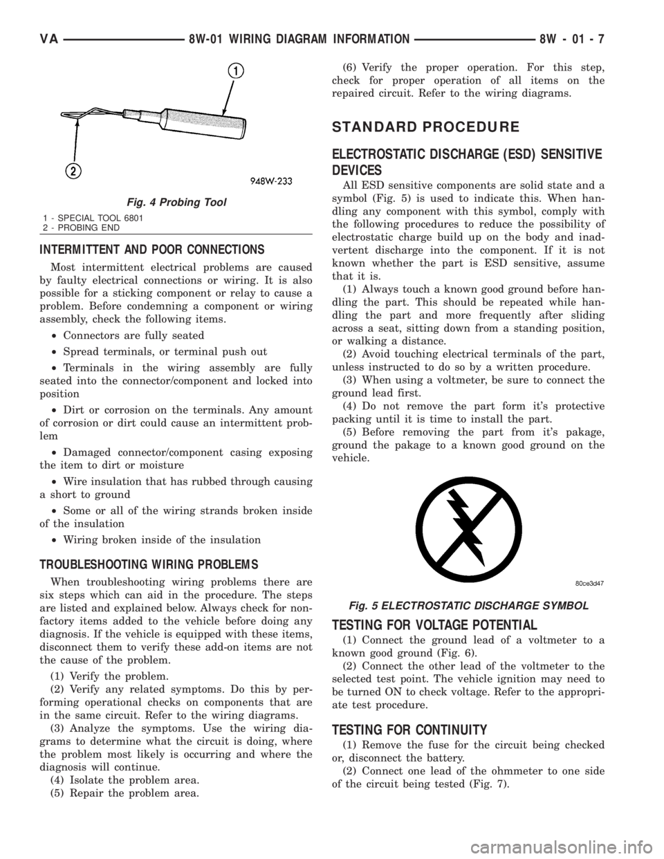
All ESD sensitive components are solid state and a
symbol (Fig. 5) is used to indicate this. When han-
dling any component with this symbol, comply with
the following procedures to reduce the possibility of
electrostatic charge build up on the body and inad-
vertent discharge into the component. If it is not
known whether the part is ESD sensitive, assume
that it is.
(1) Always touch a known good ground before han-
dling the part. This should be repeated while han-
dling the part and more frequently after sliding
across a seat, sitting down from a standing position,
or walking a distance.
(2) Avoid touching electrical terminals of the part,
unless instructed to do so by a written procedure.
(3) When using a voltmeter, be sure to connect the
ground lead first.
(4) Do not remove the part form it's protective
packing until it is time to install the part.
(5) Before removing the part from it's pakage,
ground the pakage to a known good ground on the
vehicle.
TESTING FOR VOLTAGE POTENTIAL
(1) Connect the ground lead of a voltmeter to a
known good ground (Fig. 6).
(2) Connect the other lead of the voltmeter to the
selected test point. The vehicle ignition may need to
be turned ON to check voltage. Refer to the appropri-
ate test procedure.
TESTING FOR CONTINUITY
(1) Remove the fuse for the circuit being checked
or, disconnect the battery.
(2) Connect one lead of the ohmmeter to one side
of the circuit being tested (Fig. 7).
Fig. 4 Probing Tool
1 - SPECIAL TOOL 6801
2 - PROBING END
Fig. 5 ELECTROSTATIC DISCHARGE SYMBOL
VA8W-01 WIRING DIAGRAM INFORMATION 8W - 01 - 7
Page 1089 of 2305
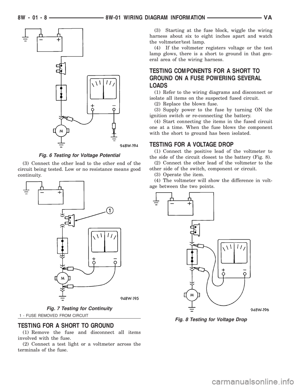
(3) Connect the other lead to the other end of the
circuit being tested. Low or no resistance means good
continuity.
TESTING FOR A SHORT TO GROUND
(1) Remove the fuse and disconnect all items
involved with the fuse.
(2) Connect a test light or a voltmeter across the
terminals of the fuse.(3) Starting at the fuse block, wiggle the wiring
harness about six to eight inches apart and watch
the voltmeter/test lamp.
(4) If the voltmeter registers voltage or the test
lamp glows, there is a short to ground in that gen-
eral area of the wiring harness.
TESTING COMPONENTS FOR A SHORT TO
GROUND ON A FUSE POWERING SEVERAL
LOADS
(1) Refer to the wiring diagrams and disconnect or
isolate all items on the suspected fused circuit.
(2) Replace the blown fuse.
(3) Supply power to the fuse by turning ON the
ignition switch or re-connecting the battery.
(4) Start connecting the items in the fused circuit
one at a time. When the fuse blows the component
with the short to ground has been isolated.
TESTING FOR A VOLTAGE DROP
(1) Connect the positive lead of the voltmeter to
the side of the circuit closest to the battery (Fig. 8).
(2) Connect the other lead of the voltmeter to the
other side of the switch, component or circuit.
(3) Operate the item.
(4) The voltmeter will show the difference in volt-
age between the two points.Fig. 6 Testing for Voltage Potential
Fig. 7 Testing for Continuity
1 - FUSE REMOVED FROM CIRCUITFig. 8 Testing for Voltage Drop
8W - 01 - 8 8W-01 WIRING DIAGRAM INFORMATIONVA