2006 LAND ROVER FRELANDER 2 differential
[x] Cancel search: differentialPage 1400 of 3229
s ynchronizi ng hub towards the revers e gear i dler gear.
The coupl ing s leeve and s ynchronizi ng hub lock t he revers e gear idler gear at the revers e s haft.
The t orque of the engine is t rans ferred via the cl ut ch t o the input shaft. The 1s t gear on t he i nput s haft t rans fers power t ot he 1st gear idl er gear. The power is then t rans ferred t o t he revers e gear idl er gear and then t o t he reverse gear coupl ings leeve. From t here power is trans ferred to t he i nt ermedi ate s haft 1s t - 2nd and 5t h - 6th and to the final dri ve which i nt urn t rans fers power t o t he ring gear. The ring gear is connect ed to the drive s hafts t hrough the di fferenti al.
Differential
The different ial dis t ribut es dri ve from t he t ransmis s ion equally bet ween t he LH and RH front half s haft s and als o provi desdri ve torque to the rear di fferenti al vi a t he power t rans fer unit .
The different ial is locat ed at t he rear of the trans mi ss i on hous ing. Both s ides of the di fferenti al are connected to t he LHand RH drive s haft s, s upplying t orque t o t he front wheel s The different ial is als o connected t o t he Power Transfer Unit viaa s pli ned shaft to the RH s ide of t he trans mi s si on, s upplying t orque t o t he rear driveline.
Reverse Switch
The revers e s wi tch i s located i n t he front of the t rans mis s ion cas ing, above t he 1s t gear det ect ion s wi tch. The swi tch i sus ed by the Ant i-lock Brake Sys tem (ABS) module for Hil l Descent Cont rol (HDC) and als o for revers ing l amp operati on.
1st Gear Position Switch
The 1s t gear s wit ch is locat ed on t he front of the t rans mi ss ion cas ing, below t he reverse swit ch. The s wit ch is us ed by t heABS module for HDC.
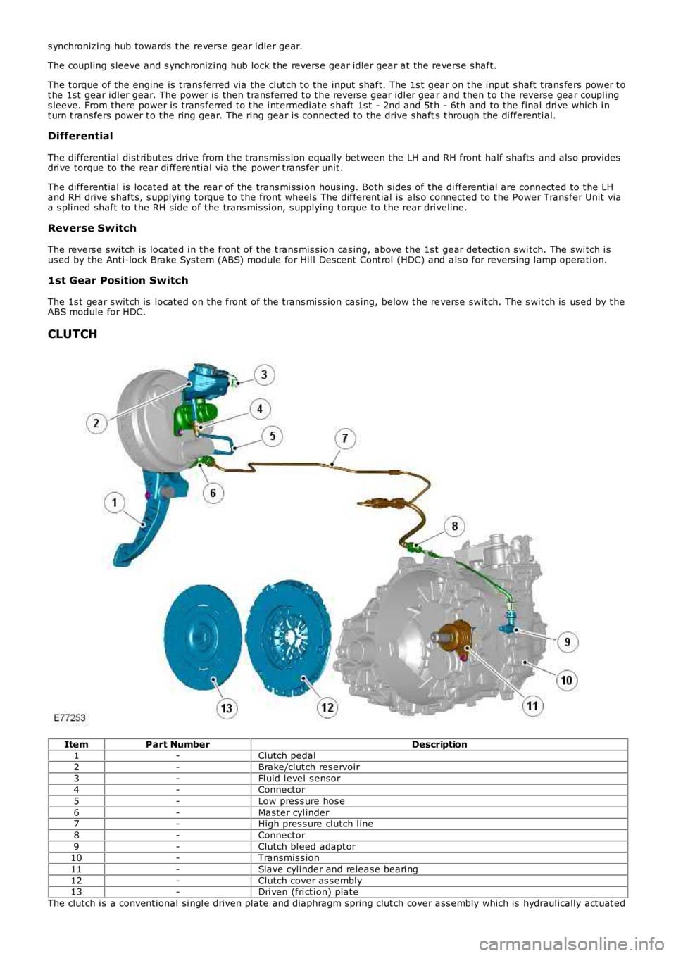
CLUTCH
ItemPart NumberDescription1-Clutch pedal
2-Brake/clut ch res ervoir
3-Fl uid l evel s ensor4-Connector
5-Low pres s ure hos e
6-Mast er cyl inder7-High pres s ure cl utch l ine
8-Connector
9-Clutch bl eed adapt or10-Transmis s ion
11-Slave cyl inder and releas e beari ng
12-Clutch cover as s embly13-Dri ven (fri ct ion) plat e
The clutch i s a convent ional si ngl e driven plat e and diaphragm spring clut ch cover ass embly which is hydraul ically act uat ed
Page 1533 of 3229
DPF Air Management Module
The DPF air management modul e control s t he fol lowing funct ions :
EGR controlTurbocharger boos t pres sure cont rolInt ake air t emperature and pres s ure control.
Duri ng act ive regenerat ion, t he EGR operat ion i s dis abl ed and t he cl osed-loop acti vat ion of t he t urbocharger boostcont rol ler is calculat ed. The ai r management module cont rols the ai r in t he int ake manifol d t o a predet ermi ned level ofpres s ure and t emperat ure. Thi s cont rol i s required t o achi eve the correct i n-cylinder condi ti ons for s table and robustcombus t ion of t he post i njected fuel.
The module controls t he i nt ake air t emperature by actuati ng t he EGR t hrott le and by adjus tment of t he turbocharger boos tpres s ure control.
DPF Co-ordinator Module
The DPF co-ordi nat or module react s t o a regenerat ion reques t from the s upervis or module by i nit iat ing and co-ordi nat ingt he foll owing DPF regenerat ion reques t s :
EGR cut-offTurbocharger boos t pres sure cont rolEngi ne load i ncreaseControl of air press ure and temperat ure in t he i nt ake manifoldFuel i njecti on cont rol.
W hen t he s upervis or modul e i ss ues a regenerat ion reques t , the co-ordinator module reques t s EGR cut-off and aregenerat ion s peci fi c turbocharger boos t pres s ure control. It then wai ts for a feedback s ignal from t he EGR s ys t emconfirming that the EGR val ve is cl osed.
W hen t he EGR valve i s clos ed, t he co-ordi nator module i nit iat es reques t s t o increas e engine l oad by cont roll ing t he i nt akeair t emperature and pres s ure.
Once confirmati on is recei ved that int ake condit ions are cont rol led or a cali brati on t ime has expired, the co-ordinatormodule t hen changes t o a s t ate awai ti ng an accelerator pedal release manoeuver from t he dri ver. If t his occurs or acal ibrat ion ti me has expired, t he co-ordi nat or modul e generates a request t o control fuel injecti ons to increas e exhaus tgas temperature.
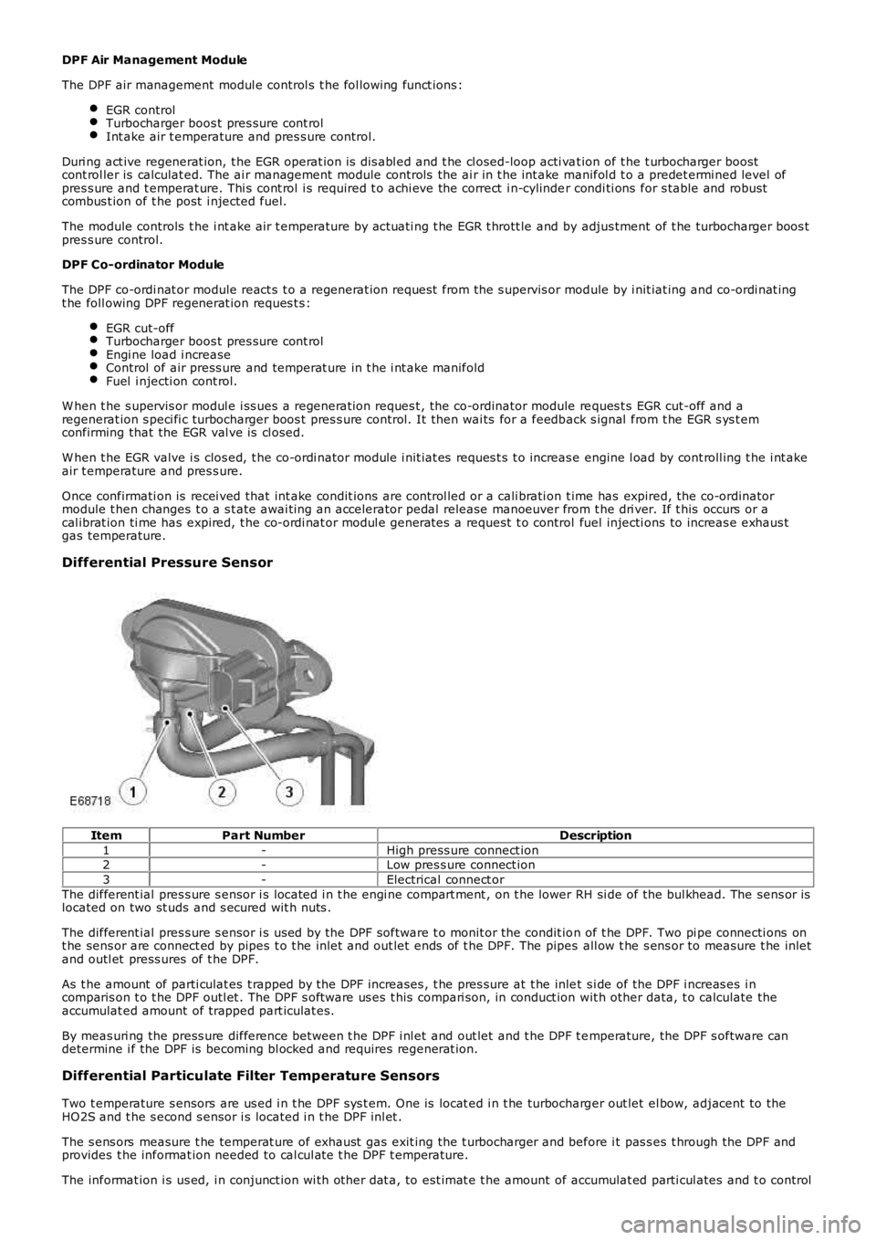
Differential Pressure Sensor
ItemPart NumberDescription
1-High press ure connect ion2-Low pres s ure connect ion
3-Electrical connect or
The different ial pres s ure s ensor i s located i n t he engi ne compart ment , on t he lower RH si de of the bul khead. The sens or islocated on two st uds and s ecured wit h nuts .
The different ial pres s ure s ensor i s us ed by the DPF software t o monit or the condit ion of t he DPF. Two pi pe connecti ons ont he sens or are connect ed by pipes t o t he inlet and out let ends of t he DPF. The pipes all ow t he s ens or to measure t he inletand outl et press ures of t he DPF.
As t he amount of parti culat es t rapped by the DPF increases , t he pres sure at t he inlet s i de of the DPF i ncreas es i ncomparis on t o t he DPF outl et . The DPF s oft ware us es t his compari son, in conduct ion wit h other data, t o calculate theaccumulat ed amount of trapped part iculat es.
By meas uri ng the press ure difference between t he DPF i nl et and out let and t he DPF t emperature, the DPF s oftware candetermine i f the DPF is becoming bl ocked and requires regenerat ion.
Differential Particulate Filter Temperature Sensors
Two t emperature s ensors are us ed i n t he DPF s ys t em. One is locat ed i n t he turbocharger out let el bow, adjacent to theHO2S and t he s econd s ensor i s located i n t he DPF inl et .
The s ens ors measure t he temperat ure of exhaust gas exit ing the t urbocharger and before i t pas s es t hrough the DPF andprovides t he informat ion needed to cal cul at e t he DPF t emperature.
The informat ion i s us ed, i n conjunct ion wi th other dat a, to est imat e t he amount of accumulat ed parti cul ates and t o control
Page 1548 of 3229
Publi s hed: 11-May-2011
Exhaust System - TD4 2.2L Diesel - Diesel Particulate Filter (DPF)
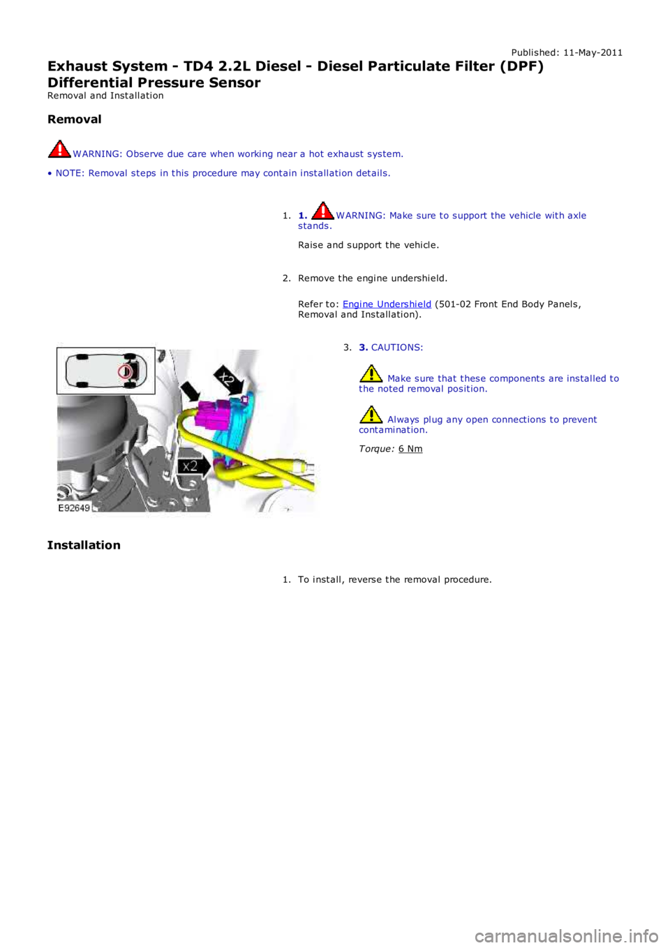
Differential Pressure Sensor
Removal and Inst all ati on
Removal W ARNING: Observe due care when worki ng near a hot exhaust s ys tem.
• NOTE: Removal s t eps in t his procedure may cont ain i nst all ati on det ail s.
1. W ARNING: Make sure t o s upport the vehicle wit h axle
s tands .
Rais e and s upport t he vehi cl e.
1.
Remove t he engi ne undershi eld.
Refer t o: Engi ne Unders hi eld (501-02 Front End Body Panel s ,
Removal and Ins tall ati on).
2. 3.
CAUTIONS: Make s ure that t hes e component s are ins tal led t o
t he noted removal pos it ion. Al ways pl ug any open connect ions t o prevent
cont ami nat ion.
T orque: 6 Nm 3.
Installation To i nst all , revers e t he removal procedure.
1.
Page 2715 of 3229
1. CAUTION: Make sure that new bolts are installed.
Clean the component mating faces.
With assistance, install the subframe.With assistance, align and secure the differential.Tighten the rear bolts.
Torque: 110 Nm
Tighten the front bolts.
Torque: 175 Nm
1.
2.
CAUTION: Make sure that new bolts are installed.
Align the suspension arms to the subframe and install the bolts, do
not fully tighten at this stage. 2.
Using the special tool, support the subframe. 3.
Connect the transmission breather lines. 4.
5. CAUTIONS:
Make sure that no components catch.
Make sure that new bolts are installed.
With assistance, position the subframe to the body and tighten the
bolts.
Torque: 175 Nm
5.
6.
CAUTION: Make sure that new bolts are installed.
Install the stabilizer clamp bolts, but do not tighten fully at this
stage. 6.
Connect the Active On-demand Coupling module electrical connector. 7.
Re mo ve t he p o we rt ra i n j a ck.
General Equi pment : P o w e rt ra i n Ja ck
8.
9.
CAUTION: Make sure that new bolts are installed.
Install the trailing arm to body brackets.
Torque: 110 Nm9.
10.
CAUTION: Make sure that the brake hose is not twisted
and is correctly located.
Clean the component mating faces.
Install the brake caliper anchor plate.
Torque: 110 Nm
Repeat the above procedure for the other side.
10.
Secure the wheel speed sensor and lead.
11.
Page 2735 of 3229
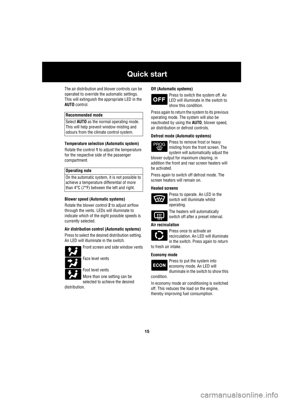
15
Quick start
R
The air distribution and blower controls can be
operated to override the automatic settings.
This will extinguish the appropriate LED in the
AUTO control.
Temperature selection (Automatic system)
Rotate the control 1 to adjust the temperature
for the respective side of the passenger
compartment.
Blower speed (Automatic systems)
Rotate the blower control 2 to adjust airflow
through the vents. LEDs will illuminate to
indicate which of the ei ght possible speeds is
currently selected.
Air distribution contro l (Automatic systems)
Press to select the desi red distribution setting.
An LED will illumina te in the switch.
Front screen and side window vents
Face level vents
Foot level vents
More than one setting can be
selected to achieve the desired
distribution. Off (Automat
ic systems)
Press to switch the system off. An
LED will illuminate in the switch to
show this condition.
Press again to return the system to its previous
operating mode. The system will also be
reactivated by using the AUTO, blower speed,
air distribution or defrost controls.
Defrost mode (Automatic systems) Press to remove frost or heavy
misting from the front screen. The
system will automatically adjust the
blower output for maximum clearing, in
addition the front and rear screen heaters will
be activated.
Press again to switch off defrost mode. The
screen heaters will remain on.
Heated screens Press to operate. An LED in the
switch will illuminate whilst
operating.
The heaters will automatically
switch off after a preset interval.
Air recirculation Press once to activate air
recirculation. An LED will illuminate
in the switch. Press again to return
to fresh air intake.
Economy mode Press to put the system into
economy mode. An LED will
illuminate in the switch to show this
condition.
In economy mode air conditioning is switched
off. This reduces the load on the engine,
thereby improving fuel consumption.
Recommended mode
Select AUTO as the normal operating mode.
This will help prevent window misting and
odours from the climate control system.
Operating note
On the automatic system, it is not possible to
achieve a temperature differential of more
than 4°C (7°F) betwee n the left and right.
Page 2842 of 3229

Transmission
122
L
TECHNICAL SPECIFICATIONS
Transmission fluids and capacities
Transmission unit Fluid spec ification Fluid capacity
Automatic gearbox Esso JWS3309 7 litres (12.3 pints) Manual gearbox Castrol MTF 97309 1.9 litres (3.3 pints)
Power transfer unit Castrol BOT118 0.75 litres (1.3 pints) Haldex coupling STAT OIL SL01- 301 0.65 litres (1.1 pints)
Rear differential Castrol EPX 0.7 litres (1.2 pints)
Page 2889 of 3229

169
Maintenance
R
TECHNICAL SPECIFICATIONS
Lubricants and fluids
¹ If Shell DOT4 ESL is not available, a low
viscosity DOT4 brake fl uid that meets ISO 4925
class 6 and Land Rover LRES22BF03
requirements may be used. Part Variant Specification
Engine oil Diesel vehicles SAE 5W-30 meeting Ford 913-B specification.
Engine oil Petrol vehicles SA E 0W-30 meeting ACEA A5
or B5 specification.
Main gearbox oil Manual tr ansmission Castrol MTF 97309
Main gearbox oil Automatic transmission Esso JWS3309US
Power transfer unit fluid Die sel vehicles Castrol BOT119
Power transfer unit fluid Petrol vehicles Castrol BOT118
Rear differential oil All vehicles Castrol EPX
Rear differential on demand
coupler fluid All vehicles STAT OIL SL01-301
Power steering fluid All vehicl es Pentosin CHF202 PAS fluid
Brake fluid All vehicles Shell DOT4 ESL ¹
Screen washer All vehicles Screen wash with frost protection
Coolant All vehicles 50% mixture of Texaco XLC antifreeze and water.
Page 2890 of 3229

Maintenance
170
L
Capacities
The quoted capacities are approximate and
provided as a guide only. All oil levels must be
checked using the dipsti ck or level plugs as
applicable. Item Variant Capacity
Fuel tank Diesel vehi cles 68 litres (15 gallons)
Petrol vehicles 70 litres (15.4 gallons)
Engine oil refill and filter change Di esel vehicles 5.86 litres (10.31 pints)
Petrol vehicles 7.7 litres (13.55 pints)
Engine oil MIN to MAX on
dipstick Diesel vehicles 1.5
litres (2.64 pints)
Petrol vehicles 0.8 litres (1.4 pints)
Manual gearbox All vehicles 2.0 litres (3.52 pints)
Automatic gearbox All vehicl es 7 litres (12.32 pints)
Power transfer unit All vehi cles 0.75 litres (1.32 pints)
Rear differential All vehi cles 0.7 litres (1.23 pints)
Rear differential coupling unit All vehicles 0.65 litres (1.14 pints)
Washer reservoir With headlamp wash 5.8 litres (10.2 pints)
Washer reservoir Without headla mp wash 3.1 litres (5.45 pints)
Cooling system (fill from dry) Al l vehicles 8.0 litres (14.07 pints)