2006 LAND ROVER FRELANDER 2 warning light
[x] Cancel search: warning lightPage 1826 of 3229
1
2
1
2
3
4
5
1
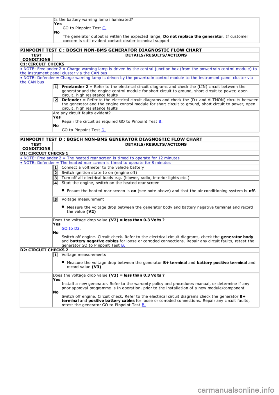
Is the bat tery warning lamp i ll uminated?YesGO t o Pi npoint Tes t C.NoThe generat or output is wit hi n t he expected range, Do not replace the generator. If cus tomerconcern i s s ti ll evident cont act dealer t echnical support
PINPOINT TEST C : BOSCH NON-BMS G ENERATOR DIAG NOSTIC FLOW CHART
T ESTCONDIT IONSDET AILS/RESULT S/ACT IONS
C1: CIRCUIT CHECKS
• NOTE: Freel ander 2 = Charge warni ng lamp is driven by t he cent ral juncti on box (from t he powert rain cont rol module) tot he ins trument panel clus ter via the CAN bus
• NOTE: Defender = Charge warning lamp i s dri ven by the powertrain control modul e t o the ins trument panel cl ust er viat he CAN busFreelander 2 = Refer t o t he elect rical circui t diagrams and check t he (LIN) ci rcuit bet ween thegenerat or and the engine control modul e for s hort ci rcuit t o ground, short ci rcuit to power, openci rcuit , hi gh res i st ance fault s
Defender = Refer to the el ect ri cal circuit di agrams and check the (D+ and ALTMON) circui ts bet weenthe generat or and t he engine control modul e for s hort circui t to ground, s hort circui t t o power, openci rcuit , hi gh res i st ance fault s
Are any circui t fault s evident?YesRepair t he circui t as required GO t o Pi npoi nt Tes t B.NoGO t o Pinpoint Tes t D.
PINPOINT TEST D : BOSCH NON-BMS GENERATOR DIAGNOSTIC FLOW CHART
T ESTCO NDIT IONSDET AILS/RESULT S/ACT IONS
D1: CIRCUIT CHECKS 1
• NOTE: Freel ander 2 = The heat ed rear s creen i s ti med t o operat e for 12 minutes• NOTE: Defender = The heat ed rear s creen is t imed to operate for 8 mi nutes
Connect a volt meter t o t he vehi cl e batt ery
Swit ch ignit ion s t at e t o on (engine off)
Turn off al l elect rical l oads e.g. (bl ower, radio, i nt eri or light s etc.)
Start the engine, s wit ch on the heat ed rear s creen
Ens ure the heated rear s creen is on (s ee note above) and t hat t he air condi ti oning s yst em is off.
Vol tage meas urement
Meas ure the volt age drop bet ween the generat or body and bat tery negat ive t ermi nal and recordthe value (V2)
Does t he volt age drop value (V2) = less than 0.3 Volts ?YesGO t o D2.NoSwit ch off engi ne. Ci rcuit check. Refer t o t he electrical ci rcuit diagrams, check the generator bodyand battery negative cables for loos e or corroded connecti ons . Repair any circuit fault s, retes t t hegenerat or GO t o Pi npoint Tes t B.D2: CIRCUIT CHECKS 2
Vol tage meas urement s
Meas ure the volt age drop bet ween the generat or B+ terminal and battery positive terminal andrecord value (V3)
Does t he volt age drop value (V3) = less than 0.3 Volts ?YesIns tal l a new generator. Refer to the warrant y policy and procedures manual, or determine if anyprior approval programme is i n operat ion, prior t o t he ins t al lat ion of a new modul e/componentNoSwit ch off engi ne. Ci rcuit check. Refer t o t he electrical ci rcuit diagrams check t he generator B+terminal and positive battery cables for l oose or corroded connect ions . Repai r any ci rcuit faul ts ,ret es t t he generator GO to Pi npoi nt Tes t B.
Page 1920 of 3229
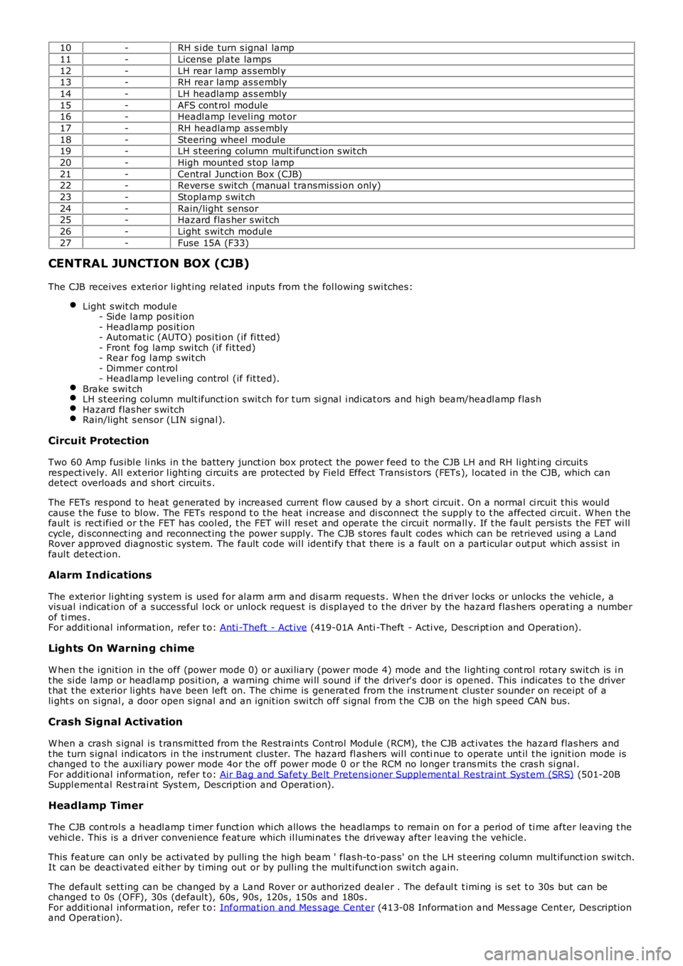
10-RH s i de turn s ignal lamp
11-Licens e pl ate lamps
12-LH rear l amp as s embl y13-RH rear lamp as s embly
14-LH headlamp as s embly
15-AFS cont rol module16-Headl amp l evel ing mot or
17-RH headlamp as s embly
18-Steering wheel modul e19-LH s t eering column mult ifunct ion s wit ch
20-High mount ed s top lamp
21-Central Junct ion Box (CJB)22-Revers e s wit ch (manual transmis si on only)
23-Stoplamp s wit ch
24-Rain/light s ensor25-Hazard flas her s wi tch
26-Light s wit ch modul e
27-Fuse 15A (F33)
CENTRAL JUNCTION BOX (CJB)
The CJB receives exteri or li ght ing relat ed inputs from t he fol lowing s wi tches:
Light s wit ch modul e- Side l amp pos it ion- Headlamp pos it ion- Automat ic (AUTO) posi ti on (if fi tt ed)- Front fog lamp swi tch (if fit ted)- Rear fog l amp s wit ch- Dimmer cont rol- Headlamp l evel ing control (if fit ted).Brake s wi tchLH s t eering column mult ifunct ion s wit ch for t urn si gnal i ndi cat ors and hi gh beam/headl amp flas hHazard flas her s wi tchRain/light s ensor (LIN si gnal ).
Circuit Protection
Two 60 Amp fus ibl e li nks in t he batt ery junct ion box protect the power feed to the CJB LH and RH li ght ing ci rcuit sres pect ively. All ext erior l ighti ng ci rcuit s are prot ect ed by Field Effect Trans is t ors (FETs ), l ocat ed in the CJB, which candetect overloads and s hort circuit s .
The FETs res pond to heat generated by increased current fl ow caus ed by a s hort ci rcuit . On a normal ci rcuit t his woul dcaus e t he fus e to bl ow. The FETs respond t o t he heat i ncrease and di s connect t he s uppl y t o t he affect ed ci rcuit . W hen t hefaul t is rect ified or t he FET has cool ed, t he FET wil l res et and operate t he circui t normall y. If t he faul t pers is ts the FET wi llcycle, di sconnect ing and reconnect ing t he power supply. The CJB s tores fault codes which can be ret rieved usi ng a LandRover approved diagnost ic sys tem. The fault code wil l identi fy t hat there is a fault on a part icular out put which as si s t infaul t det ect ion.
Alarm Indications
The exteri or li ght ing s ys tem is us ed for al arm arm and dis arm reques ts . W hen t he driver l ocks or unlocks the vehicle, avis ual i ndicat ion of a s uccess ful l ock or unlock reques t is di spl ayed t o t he dri ver by the hazard flas hers operat ing a numberof ti mes .For addit ional informat ion, refer t o: Anti -Theft - Act ive (419-01A Anti -Theft - Acti ve, Des cri pt ion and Operati on).
Lights On Warning chime
W hen t he i gni ti on in the off (power mode 0) or auxi liary (power mode 4) mode and the l ighti ng cont rol rotary swit ch is i nt he si de lamp or headlamp posi ti on, a warning chime wi ll s ound i f the driver's door is opened. This indicates t o t he dri vert hat t he exterior li ght s have been left on. The chime is generat ed from t he i ns t rument clus ter s ounder on receipt of ali ght s on s i gnal , a door open s ignal and an ignit ion swi tch off s ignal from t he CJB on the hi gh s peed CAN bus.
Crash Signal Activation
W hen a crash s ignal i s t rans mit ted from t he Rest rai nts Cont rol Modul e (RCM), t he CJB act ivat es the hazard flas hers andt he turn s ignal indicators in t he i ns t rument clus ter. The hazard fl ashers wil l continue to operate unt il t he ignit ion mode ischanged t o t he auxi liary power mode 4or the off power mode 0 or the RCM no longer trans mi ts the cras h si gnal .For addit ional informat ion, refer t o: Air Bag and Safet y Belt Pretens ioner Supplement al Res traint Syst em (SRS) (501-20BSuppl ement al Rest rai nt Sys tem, Des cri pti on and Operati on).
Headlamp Timer
The CJB cont rol s a headl amp t imer funct ion whi ch allows the headlamps t o remain on for a peri od of ti me after leaving t hevehi cl e. Thi s is a dri ver conveni ence feat ure which il lumi nat es t he dri veway after leaving t he vehicle.
This feat ure can onl y be acti vat ed by pulli ng t he high beam ' flas h-t o-pas s' on t he LH s t eering column mult ifunct ion s wi tch.It can be deacti vat ed eit her by ti ming out or by pull ing t he mul ti funct ion swi tch again.
The default s ett ing can be changed by a Land Rover or authorized deal er . The default t imi ng is s et t o 30s but can bechanged t o 0s (OFF), 30s (defaul t), 60s , 90s , 120s , 150s and 180s .For addit ional informat ion, refer t o: Informat ion and Mes s age Cent er (413-08 Informat ion and Mes s age Cent er, Des cript ionand Operat ion).
Page 1927 of 3229
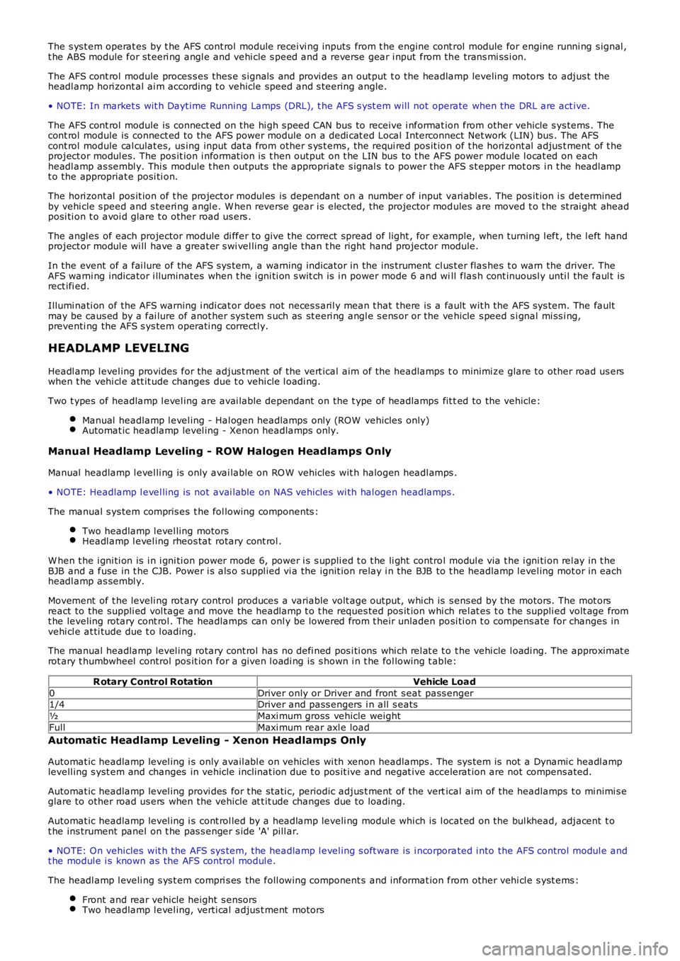
The s ys t em operat es by t he AFS cont rol module recei vi ng inputs from t he engine cont rol module for engine runni ng s ignal ,t he ABS module for st eeri ng angl e and vehi cle s peed and a reverse gear i nput from the trans mi ss i on.
The AFS cont rol module proces s es thes e s ignals and provi des an output t o the headlamp leveling motors to adjus t theheadl amp hori zont al ai m according t o vehicle speed and s teering angle.
• NOTE: In market s wit h Dayt ime Running Lamps (DRL), t he AFS s yst em will not operate when the DRL are act ive.
The AFS cont rol module is connect ed on the hi gh s peed CAN bus to receive i nformat ion from other vehicle s ys tems . Thecont rol module is connect ed to the AFS power module on a dedi cat ed Local Interconnect Net work (LIN) bus . The AFScont rol module cal culat es, us ing input dat a from other s ys t ems , the requi red pos it ion of t he hori zont al adjus t ment of t heproject or modul es. The pos it ion i nformat ion is t hen output on t he LIN bus to t he AFS power module l ocat ed on eachheadl amp as sembl y. Thi s module t hen outputs the appropriate s ignal s t o power the AFS s t epper mot ors i n t he headl ampt o the appropriat e posi ti on.
The hori zont al pos it ion of t he project or modul es is dependant on a number of input vari abl es . The pos it ion i s determinedby vehi cle s peed and s teeri ng angl e. W hen reverse gear i s elected, the projector modules are moved t o t he st rai ght aheadposi ti on t o avoi d glare t o other road us ers .
The angl es of each projector module di ffer to gi ve the correct spread of light , for example, when turning l eft , the l eft handproject or modul e wi ll have a great er s wi vel ling angl e than t he right hand projector module.
In the event of a fai lure of the AFS sys tem, a warning indicator in the ins trument cl us t er flas hes t o warn the driver. TheAFS warni ng indicator i lluminates when t he i gni ti on s wit ch is i n power mode 6 and will flas h cont inuousl y unti l the faul t isrect ifi ed.
Illumi nati on of the AFS warning i ndi cat or does not neces s aril y mean t hat there is a fault wit h the AFS sys tem. The faultmay be caus ed by a fai lure of anot her sys tem s uch as st eeri ng angl e s ens or or the vehicle s peed s i gnal mi ss i ng,preventi ng the AFS s ys tem operati ng correctl y.
HEADLAMP LEVELING
Headl amp l evel ing provides for the adjus t ment of the vert ical aim of the headlamps to minimi ze glare to other road us erswhen t he vehi cl e att it ude changes due t o vehi cle l oadi ng.
Two t ypes of headlamp l evel ing are avai lable dependant on the t ype of headlamps fit ted to the vehicle:
Manual headlamp l evel ing - Hal ogen headlamps only (ROW vehicles only)Automat ic headlamp level ing - Xenon headlamps only.
Manual Headlamp Leveling - ROW Halogen Headlamps Only
Manual headlamp l evel li ng is only avai lable on RO W vehicles wit h halogen headl amps .
• NOTE: Headlamp l evel ling is not avai lable on NAS vehicles wi th hal ogen headlamps .
The manual s ys tem compris es t he fol lowing components :
Two headlamp l evel ling motorsHeadl amp l evel ing rheos tat rotary cont rol .
W hen t he i gni ti on is i n i gni ti on power mode 6, power i s s uppli ed t o t he li ght control modul e via t he i gni ti on rel ay in t heBJB and a fuse in t he CJB. Power i s als o s uppl ied vi a the ignit ion relay i n the BJB to t he headlamp l evel ing mot or in eachheadl amp as sembl y.
Movement of t he leveli ng rot ary control produces a variable volt age output, whi ch is s ens ed by the motors. The mot orsreact to the suppli ed vol tage and move the headlamp t o t he reques ted pos it ion whi ch rel at es t o t he suppli ed volt age fromt he leveling rotary cont rol . The headlamps can onl y be lowered from t heir unladen posi ti on t o compens ate for changes invehi cl e at ti tude due t o l oading.
The manual headlamp level ing rotary cont rol has no defi ned pos i ti ons whi ch rel at e t o t he vehi cle l oadi ng. The approximat erot ary t humbwheel control pos it ion for a given l oadi ng is s hown i n t he fol lowing t able:
R otary Control RotationVehicle Load
0Driver only or Driver and front s eat pass enger1/4Driver and pass engers i n all s eats
½Maxi mum gross vehicle weight
FullMaxi mum rear axl e load
Automatic Headlamp Leveling - Xenon Headlamps Only
Automat ic headlamp level ing i s only avail abl e on vehicles wi th xenon headlamps . The sys tem is not a Dynami c headl amplevell ing s yst em and changes in vehicle inclinat ion due t o pos it ive and negat ive accelerat ion are not compens ated.
Automat ic headlamp level ing provi des for t he st ati c, periodic adjus t ment of the vertical aim of the headlamps t o mi nimi s eglare to other road us ers when the vehicle at t it ude changes due to loading.
Automat ic headlamp level ing i s cont rol led by a headlamp leveli ng modul e whi ch is l ocat ed on the bul khead, adjacent t ot he ins trument panel on t he pas s enger s ide 'A' pill ar.
• NOTE: On vehicles wit h the AFS sys tem, the headlamp l evel ing s oft ware is i ncorporated i nto the AFS control modul e andt he modul e i s known as the AFS control modul e.
The headl amp l eveli ng s ys t em compri s es the foll owing component s and informat ion from other vehi cl e s yst ems :
Front and rear vehicle height s ensorsTwo headlamp l evel ing, verti cal adjus t ment motors
Page 1930 of 3229
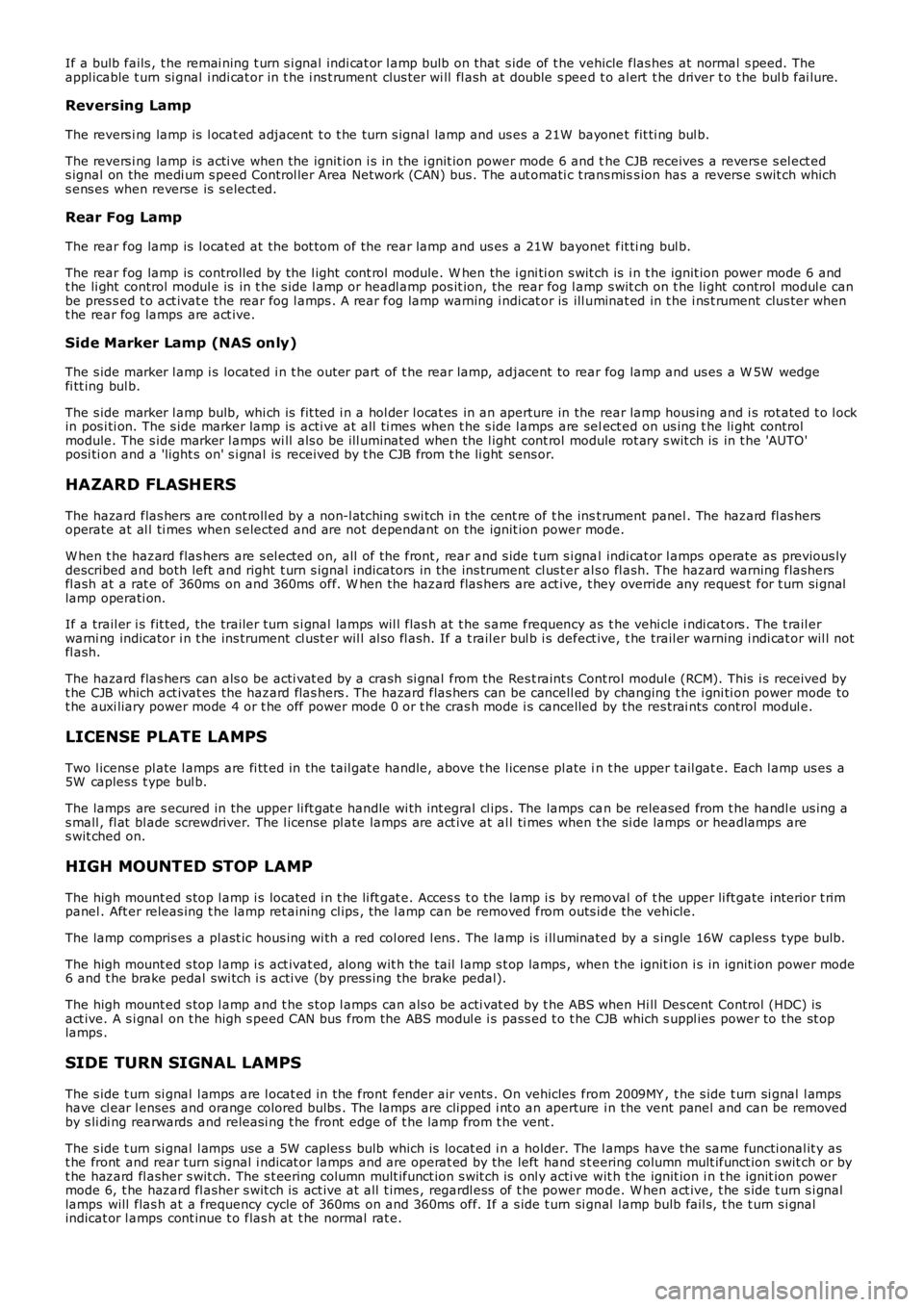
If a bulb fails , t he remai ning t urn s i gnal indi cat or l amp bulb on that s ide of t he vehicle flas hes at normal s peed. Theappl icable t urn si gnal i ndi cat or in t he i ns t rument clus ter wi ll fl ash at double s peed t o al ert t he driver t o t he bul b fai lure.
Reversing Lamp
The revers i ng lamp is l ocat ed adjacent t o t he turn s ignal lamp and us es a 21W bayonet fit ti ng bul b.
The revers i ng lamp is acti ve when the ignit ion i s in the i gnit ion power mode 6 and the CJB receives a revers e s el ect eds ignal on the medi um s peed Control ler Area Network (CAN) bus . The aut omati c t rans miss ion has a revers e s wit ch whichs ens es when reverse is s elect ed.
Rear Fog Lamp
The rear fog lamp is l ocat ed at the bot tom of the rear lamp and us es a 21W bayonet fit ti ng bul b.
The rear fog lamp is controlled by the l ight cont rol module. W hen the i gni ti on s wit ch is i n t he ignit ion power mode 6 andt he li ght control modul e is in t he s ide l amp or headl amp pos it ion, the rear fog l amp s wit ch on t he li ght control modul e canbe pres s ed t o act ivat e the rear fog l amps . A rear fog lamp warning i ndicat or is ill uminat ed in t he i ns t rument clus ter whent he rear fog lamps are act ive.
Side Marker Lamp (NAS only)
The s ide marker l amp i s located i n t he outer part of t he rear lamp, adjacent to rear fog lamp and us es a W 5W wedgefi tt ing bul b.
The s ide marker l amp bulb, whi ch is fit ted i n a hol der l ocat es in an aperture in the rear lamp hous ing and i s rot ated t o l ockin pos i ti on. The s ide marker lamp is acti ve at all ti mes when t he s ide l amps are select ed on us ing t he li ght controlmodule. The s ide marker l amps wi ll als o be i ll uminated when the l ight cont rol module rot ary s wit ch is in t he 'AUTO'posi ti on and a 'light s on' s i gnal is received by t he CJB from t he li ght sens or.
HAZARD FLASHERS
The hazard flas hers are cont roll ed by a non-l atching s wi tch i n the cent re of t he inst rument panel . The hazard fl as hersoperate at al l ti mes when s elected and are not dependant on the ignit ion power mode.
W hen t he hazard flas hers are s el ect ed on, all of the front , rear and s ide t urn s i gnal indi cat or l amps operate as previous lydescribed and both left and right t urn s ignal indicators in the ins trument cl us t er al s o fl ash. The hazard warning flas hersfl ash at a rat e of 360ms on and 360ms off. W hen the hazard flas hers are act ive, t hey override any reques t for t urn si gnallamp operati on.
If a trail er i s fit ted, the trailer t urn s i gnal lamps wil l flas h at t he s ame frequency as t he vehi cle i ndi cat ors . The t rail erwarni ng indicator i n t he ins trument cl ust er wil l al s o fl ash. If a t rail er bul b i s defect ive, t he trail er warning i ndi cat or wil l notfl ash.
The hazard flas hers can als o be acti vat ed by a crash si gnal from the Res t raint s Control modul e (RCM). This i s received byt he CJB which act ivat es the hazard flas hers . The hazard flas hers can be cancell ed by changing t he i gni ti on power mode tot he auxi liary power mode 4 or t he off power mode 0 or t he cras h mode i s cancelled by the res trai nts control modul e.
LICENSE PLATE LAMPS
Two l icens e pl ate l amps are fi tt ed in the t ail gat e handle, above t he l icens e pl ate in t he upper t ail gat e. Each l amp us es a5W caples s t ype bul b.
The lamps are s ecured in the upper li ft gat e handle wi th int egral cl ips . The lamps can be released from t he handl e us ing as mall , fl at bl ade screwdriver. The l icense pl ate lamps are act ive at al l ti mes when t he si de lamps or headlamps ares wit ched on.
HIGH MOUNTED STOP LAMP
The high mount ed s top l amp i s located i n t he li ft gat e. Acces s t o the lamp i s by removal of t he upper li ft gate interior t rimpanel . Aft er releas ing t he lamp ret aining cl ips , the l amp can be removed from outs ide the vehicle.
The lamp compris es a pl ast ic hous ing wi th a red col ored l ens . The lamp is i ll uminated by a s ingle 16W caples s type bulb.
The high mount ed s top l amp i s act ivat ed, along wit h the tail l amp s t op lamps , when the ignit ion i s in ignit ion power mode6 and t he brake pedal swi tch i s acti ve (by pres s ing the brake pedal).
The high mount ed s top l amp and t he s top l amps can als o be acti vat ed by t he ABS when Hi ll Des cent Control (HDC) isact ive. A s i gnal on t he high s peed CAN bus from the ABS modul e i s pass ed t o t he CJB which s uppl ies power to the st oplamps .
SIDE TURN SIGNAL LAMPS
The s ide t urn si gnal l amps are l ocat ed in the front fender air vents . On vehicles from 2009MY , t he s ide t urn si gnal l ampshave cl ear l enses and orange colored bulbs . The lamps are clipped i nt o an aperture in the vent panel and can be removedby s li di ng rearwards and releasi ng t he front edge of t he lamp from t he vent .
The s ide t urn si gnal l amps use a 5W caples s bulb which is locat ed i n a holder. The lamps have the same functi onal it y ast he front and rear turn s ignal i ndicat or lamps and are operat ed by the left hand s t eering column mult ifunct ion s wit ch or byt he hazard fl asher s wit ch. The s t eering column mult ifunct ion s wit ch is onl y acti ve wit h t he ignit ion i n t he ignit ion powermode 6, t he hazard fl asher s wit ch is act ive at all t imes , regardl ess of t he power mode. W hen act ive, t he s ide t urn s i gnallamps will flas h at a frequency cycle of 360ms on and 360ms off. If a s ide t urn si gnal l amp bulb fail s, t he t urn s i gnalindicat or l amps cont inue t o flas h at t he normal rat e.
Page 1931 of 3229
TRAILER LIGHTING
Several di fferent types of trail er s ocket can be fit ted to the vehicle depending on market specificat ions . Refer t o theElectrical Reference Library for s peci fi c s ocket det ail s.
The CJB monit ors t he t urn s i gnal indicat or l amps and can det ect if more t han two lamps are fi tt ed (the s i de turn s ignallamps are not monit ored). W hen a t rai ler is det ect ed, t he t rai ler warning indicator in the ins trument cl us t er will flas h i ns ynchronis at ion wi th the t urn si gnal i ndi cat ors .
If one or more of t he turn s ignal indicator l amps on the vehicl e or the t rai ler are defect ive, t he trailer warning i ndi cat or willnot fl as h to al ert t he dri ver t o t he bulb failure.
DIAGNOSTICS
The diagnost ic s ocket i s located in t he lower i ns t rument panel clos ing panel, on the driver's si de, bel ow t he s teeri ngcol umn. Various l ighti ng s yst em funct ions are monit ored by di fferent sys t ems which can s tore faul t informati on. Thi s canbe ret rieved usi ng a Land Rover approved diagnost ic sys tem.
Page 2723 of 3229

Contents
3
R
Quick start
QUICK START ................................................... 7
Filling station information
FILLING STATION INFORMATION................... 33
Introduction
SYMBOLS GLOSSARY .................................... 35
LABEL LOCATIONS ......................................... 35
HEALTH AND SAFETY ..................................... 36
DATA RECORDING.......................................... 37
DISABILITY MODIFICATIONS ......................... 37
PARTS AND ACCESSORIES ............................ 37
Keys and remote controls
USING THE KEY .............................................. 40
GENERAL INFORMATION ON RADIO
FREQUENCIES ................................................ 40
USING THE REMOTE CONTROL ..................... 41
Locks
LOCKING AND UNLOCKING ............................ 44
Alarm
ARMING THE ALARM ..................................... 45
DISARMING THE ALARM ............................... 46
Seats
SITTING IN THE CORRECT POSITION ............ 47
MANUAL SEATS ............................................. 48
ELECTRIC SEATS ............................................ 49
HEAD RESTRAINTS ........................................ 51
REAR SEATS................................................... 51
HEATED SEATS............................................... 53
Seat belts
PRINCIPLE OF OPERATION ............................ 54
SEAT BELT REMINDER ................................... 55
FASTENING THE SEAT BELTS ........................ 56
SEAT BELT HEIGHT ADJUSTMENT................. 56
USING SEAT BELTS DURI NG PREGNANCY .... 57
Supplementary restraints system
PRINCIPLE OF OPERATION ............................ 58
AIRBAG WARNING LAMP ............................... 61
DISABLING THE PASSENGER AIRBAG ........... 62
AIRBAG SERVICE INFORMATION ................... 63
Child safety
CHILD SEATS ................................................. 64
BOOSTER CUSHIONS ..................................... 66
ISOFIX ANCHOR POINTS................................ 67
CHILD SAFETY LOCKS ................................... 69
Steering wheel
ADJUSTING THE STEERING WHEEL .............. 70
AUDIO CONTROL ........................................... 70
Lighting
LIGHTING CONTROL ...................................... 72
FRONT FOG LAMPS........................................ 72
REAR FOG LAMPS.......................................... 73
ADJUSTING THE HEADLAMPS....................... 73
HEADLAMP LEVELLING ................................. 73
HAZARD WARNING FLASHERS...................... 74
ADAPTIVE FRONT LIGHTING SYSTEM (AFS) . 74
DIRECTION INDICATORS ............................... 75
INTERIOR LAMPS .......................................... 76
APPROACH LAMPS ........................................ 76
CHANGING A BULB ........................................ 77
BULB SPECIFICATION CHART ........................ 86
Wipers and washers
WINDSCREEN WIPERS .................................. 87
RAIN SENSOR ................................................ 87
WINDSCREEN WASHERS............................... 88
HEADLAMP WASHERS................................... 88
REAR WINDOW WIPER AND WASHERS ........ 89
ADJUSTING THE WINDSCREEN WASHER JETS .
89
CHECKING THE WIPER BLADES .................... 90
CHANGING THE WIPER BLADES.................... 90
Windows and mirrors
ELECTRIC WINDOWS ..................................... 93
EXTERIOR MIRRORS ..................................... 94
ELECTRIC EXTERIOR MIRRORS .................... 95
INTERIOR MIRROR ........................................ 96
Instruments
INSTRUMENT PANEL OVERVIEW .................. 97
Information displays
TRIP COMPUTER ........................................... 99
INFORMATION MESSAGES ............................ 99
Page 2741 of 3229
21
Quick start
R
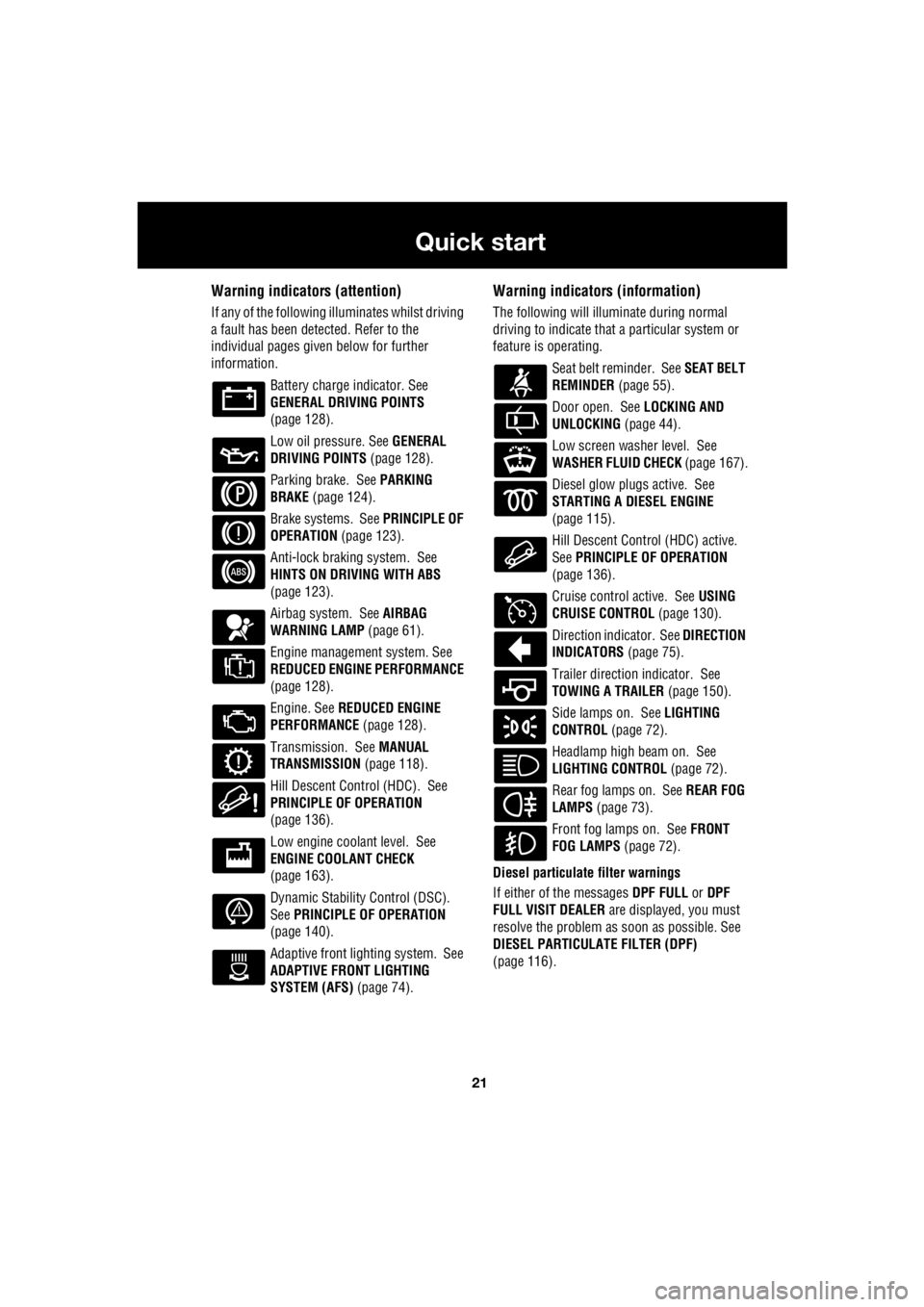
Warning indicators (attention)
If any of the following illuminates whilst driving
a fault has been detected. Refer to the
individual pages give n below for further
information.
Battery charge indicator. See
GENERAL DRIVING POINTS
(page 128).
Low oil pressure. See GENERAL
DRIVING POINTS (page 128).
Parking brake. See PARKING
BRAKE (page 124).
Brake systems. See PRINCIPLE OF
OPERATION (page 123).
Anti-lock braking system. See
HINTS ON DRIVING WITH ABS
(page 123).
Airbag system. See AIRBAG
WARNING LAMP (page 61).
Engine management system. See
REDUCED ENGINE PERFORMANCE
(page 128).
Engine. See REDUCED ENGINE
PERFORMANCE (page 128).
Transmission. See MANUAL
TRANSMISSION (page 118).
Hill Descent Control (HDC). See
PRINCIPLE OF OPERATION
(page 136).
Low engine coolant level. See
ENGINE COOLANT CHECK
(page 163).
Dynamic Stability Control (DSC).
See PRINCIPLE OF OPERATION
(page 140).
Adaptive front lighting system. See
ADAPTIVE FRONT LIGHTING
SYSTEM (AFS) (page 74).
Warning indicators (information)
The following will illuminate during normal
driving to indicate that a particular system or
feature is operating.
Seat belt reminder. See SEAT BELT
REMINDER (page 55).
Door open. See LOCKING AND
UNLOCKING (page 44).
Low screen washer level. See
WASHER FLUID CHECK (page 167).
Diesel glow plugs active. See
STARTING A DIESEL ENGINE
(page 115).
Hill Descent Control (HDC) active.
See PRINCIPLE OF OPERATION
(page 136).
Cruise control active. See USING
CRUISE CONTROL (page 130).
Direction indicator. See DIRECTION
INDICATORS (page 75).
Trailer direction indicator. See
TOWING A TRAILER (page 150).
Side lamps on. See LIGHTING
CONTROL (page 72).
Headlamp high beam on. See
LIGHTING CONTROL (page 72).
Rear fog lamps on. See REAR FOG
LAMPS (page 73).
Front fog lamps on. See FRONT
FOG LAMPS (page 72).
Diesel particulate filter warnings
If either of the messages DPF FULL or DPF
FULL VISIT DEALER are displayed, you must
resolve the problem as soon as possible. See
DIESEL PARTICULATE FILTER (DPF)
(page 116).
Page 2761 of 3229
41
Keys and remote controls
R
USING THE REMOTE CONTROL
Remote control
Note: The operational range of the remote
control will vary considerably depending on
atmospheric conditions and interference from
other transmitting devices.
The vehicle is supplied with two remote
controls, but up to six can be programmed to
the vehicle at any one time.
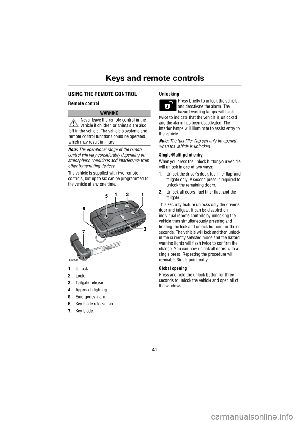
1. Unlock.
2. Lock.
3. Tailgate release.
4. Approach lighting.
5. Emergency alarm.
6. Key blade release tab.
7. Key blade.
Unlocking
Press briefly to unlock the vehicle,
and deactivate the alarm. The
hazard warning lamps will flash
twice to indicate that the vehicle is unlocked
and the alarm has been deactivated. The
interior lamps will illuminate to assist entry to
the vehicle.
Note: The fuel filler flap can only be opened
when the vehicle is unlocked.
Single/Multi- point entry
When you press the unlock button your vehicle
will unlock in one of two ways:
1. Unlock the driver's door, fuel filler flap, and
tailgate only. A second press is required to
unlock the remaining doors.
2. Unlock all doors, fuel filler flap, and the
tailgate.
This security feature unlocks only the driver’s
door and tailgate. It can be disabled on
individual remote controls by unlocking the
vehicle then simultaneously pressing and
holding the lock and unlock buttons for three
seconds. The vehicle will lock and then unlock
in the currently selected mode and the hazard
warning lights will flas h twice to confirm the
change. You can now unlock all doors with a
single press. Repeating the procedure will
re-enable Single point entry.
Global opening
Press and hold the unlock button for three
seconds to unlock the ve hicle and open all of
the windows.
WARNING
Never leave the remote control in the
vehicle if children or animals are also
left in the vehicle. The vehicle's systems and
remote control functions could be operated,
which may result in injury.
2
E80909
451
3
6
7