2006 LAND ROVER FRELANDER 2 power steering fluid
[x] Cancel search: power steering fluidPage 531 of 3229
Publi s hed: 11-May-2011
Steering System - General Information - Power Steering System Flushing
General Procedures
• NOTE: If heavy s teering or cont aminat ion wi thi n t he power s t eering s ys tem is found, i t is necess ary to carry out t hes ys t em flus h procedure as det ailed bel ow. If any component s have been replaced in t he power st eeri ng s ys t em t heprocedure below must be carri ed out in full.
• NOTE: Some vari ati on in the i ll us t rat ions may occur, but the es s ent ial informat ion i s always correct .
1. Remove the power s teeri ng fl uid res ervoi r cap.
2. Usi ng a s uit able s yri nge, remove the power s teering fluid fromt he power s t eering flui d res ervoir.
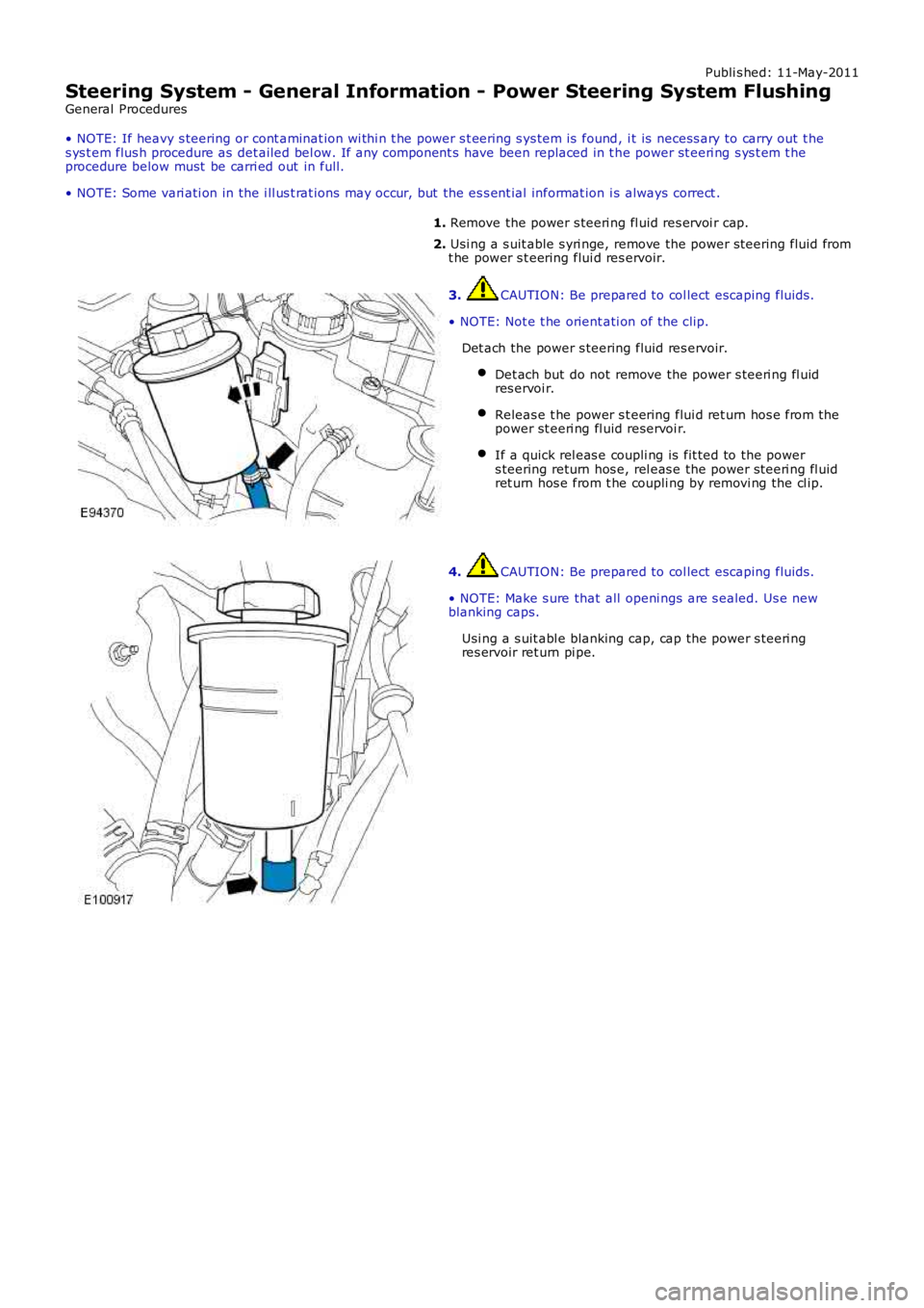
3. CAUTION: Be prepared to col lect escaping fluids .
• NOTE: Not e t he orient ati on of the cli p.
Det ach the power s teering fluid res ervoir.
Det ach but do not remove the power s teeri ng fl uidres ervoi r.
Releas e t he power s t eering flui d ret urn hos e from thepower st eeri ng fl uid reservoi r.
If a quick rel eas e coupli ng is fit ted to the powers teering return hos e, rel eas e the power s teeri ng fl uidret urn hos e from t he coupli ng by removi ng the cl ip.
4. CAUTION: Be prepared to col lect escaping fluids .
• NOTE: Make s ure that all openi ngs are s ealed. Us e newblanking caps.
Usi ng a s uit abl e blanking cap, cap the power s teeri ngres ervoir ret urn pi pe.
Page 535 of 3229
Publ is hed: 05-Dec-2011
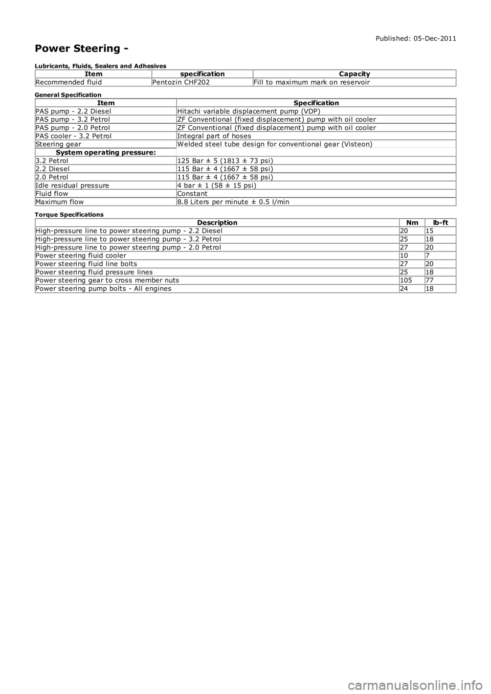
Power Steering -
Lubricants, Fluids, Sealers and AdhesivesItemspecificationCapacity
Recommended flui dPent ozi n CHF202Fil l to maxi mum mark on res ervoir
General Specification
ItemSpecification
PAS pump - 2.2 Di es elHit achi variable dis placement pump (VDP)PAS pump - 3.2 PetrolZF Conventi onal (fi xed di s pl acement ) pump wit h oi l cooler
PAS pump - 2.0 PetrolZF Conventi onal (fi xed di s pl acement ) pump wit h oi l cooler
PAS cooler - 3.2 Pet rolInt egral part of hos esSt eering gearW elded s t eel t ube des i gn for conventi onal gear (Vi st eon)
System operating pressure:
3.2 Pet rol125 Bar ± 5 (1813 ± 73 ps i)2.2 Dies el115 Bar ± 4 (1667 ± 58 ps i)
2.0 Pet rol115 Bar ± 4 (1667 ± 58 ps i)
Idle resi dual pres s ure4 bar ± 1 (58 ± 15 ps i)Flui d fl owCons tant
Maximum flow8.8 Lit ers per mi nute ± 0.5 l/min
Torque Specifications
DescriptionNmlb-ftHi gh-pres sure l ine t o power st eeri ng pump - 2.2 Dies el2015
Hi gh-pres sure l ine t o power st eeri ng pump - 3.2 Pet rol2518
Hi gh-pres sure l ine t o power st eeri ng pump - 2.0 Pet rol2720Power st eeri ng fl uid cooler107
Power st eeri ng fl uid l ine bolt s2720
Power st eeri ng fl uid pres s ure lines2518Power st eeri ng gear t o cros s member nuts10577
Power st eeri ng pump bolt s - All engines2418
Page 540 of 3229
diamet er in i ts central sect ion. The smal ler diamet er allows the t ors ion bar t o t wist in res pons e t o t orque appli ed from t hes teeri ng wheel in relati on t o t he grip of the t yres on t he road surface. The pi nion s haft has machined t eet h on it s cent raldiamet er whi ch mat e wit h t eeth on the s t eering gear rack. A s lot , machi ned in t he upper end of t he pini on s haft mateswit h t he dog-t oot h on the i nput s haft . The pinion s haft l ocat es in the pi ni on housi ng and rot ates on bal l and roll erbearings .
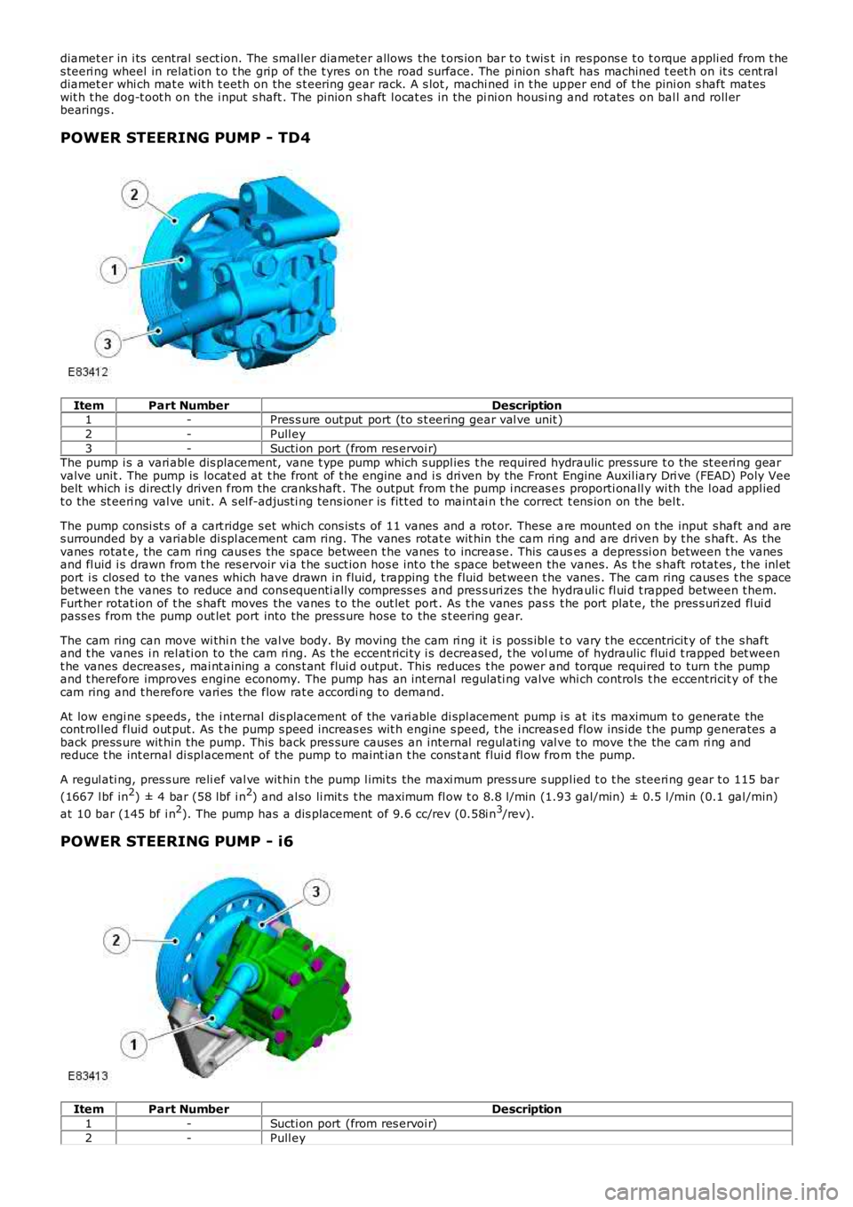
POWER STEERING PUMP - TD4
ItemPart NumberDescription1-Pres s ure out put port (t o s t eering gear val ve unit )
2-Pull ey
3-Sucti on port (from res ervoi r)The pump i s a vari abl e dis placement, vane t ype pump which s uppl ies t he required hydraulic pres sure t o the st eeri ng gearvalve unit . The pump is locat ed at t he front of t he engine and i s dri ven by the Front Engine Auxil iary Dri ve (FEAD) Poly Veebelt which i s direct ly driven from the cranks haft . The out put from t he pump i ncreas es proporti onall y wi th the l oad appl iedt o the st eeri ng val ve uni t. A s el f-adjus ti ng tens ioner is fit t ed to maint ai n t he correct t ens ion on the bel t.
The pump consi st s of a cart ridge s et which cons is t s of 11 vanes and a rot or. These are mount ed on t he input s haft and ares urrounded by a variable di spl acement cam ring. The vanes rotat e wit hin the cam ri ng and are driven by t he s haft. As thevanes rotat e, the cam ri ng caus es the space between t he vanes to increase. This causes a depres si on between t he vanesand fl uid i s drawn from t he res ervoir vi a t he suct ion hos e int o t he s pace between the vanes. As t he s haft rotat es , t he inl etport i s clos ed to the vanes which have drawn in fluid, t rapping t he fluid bet ween t he vanes . The cam ring caus es t he s pacebetween t he vanes to reduce and cons equenti ally compress es and pres s uri zes t he hydrauli c fl ui d t rapped between t hem.Furt her rotat ion of t he s haft moves the vanes t o the out let port . As t he vanes pas s t he port plat e, the pres s uri zed fl ui dpass es from the pump out let port into the press ure hose to the s t eering gear.
The cam ring can move wi thi n t he val ve body. By moving the cam ri ng it i s poss ibl e to vary t he eccentricit y of t he s haftand t he vanes i n rel ati on to the cam ri ng. As t he eccent rici ty i s decreased, t he volume of hydraulic flui d t rapped bet weent he vanes decreases , mai nt aining a cons t ant flui d output. This reduces t he power and torque required to turn t he pumpand t herefore improves engine economy. The pump has an int ernal regulati ng valve which controls t he eccentricit y of t hecam ring and t herefore vari es the flow rat e accordi ng to demand.
At low engi ne s peeds , the i nternal dis placement of the vari able di spl acement pump i s at it s maximum t o generate thecont rol led fluid out put. As t he pump s peed increas es wit h engine s peed, t he i ncreas ed flow ins ide t he pump generates aback press ure wit hin the pump. This back pres s ure causes an internal regul ati ng val ve to move t he the cam ri ng andreduce t he int ernal di spl acement of the pump to maint ian t he cons t ant flui d fl ow from the pump.
A regul ati ng, pres s ure reli ef val ve wit hin t he pump l imi ts the maxi mum press ure s uppl ied t o t he s teeri ng gear t o 115 bar
(1667 l bf in2) ± 4 bar (58 lbf i n2) and al so li mit s t he maximum fl ow t o 8.8 l/min (1.93 gal/min) ± 0.5 l /min (0.1 gal /min)
at 10 bar (145 bf i n2). The pump has a dis placement of 9.6 cc/rev (0.58i n3/rev).
POWER STEERING PUMP - i6
ItemPart NumberDescription
1-Sucti on port (from res ervoi r)
2-Pull ey
Page 552 of 3229
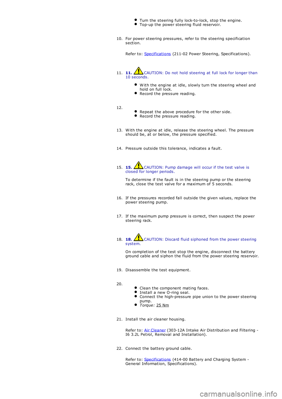
Turn the s t eering full y lock-t o-l ock, s top t he engine.
Top-up t he power st eeri ng fl uid reservoi r.
For power s t eering press ures , refer to the s t eering s peci fi cat ion
s ect ion.
Refer t o: Specificati ons (211-02 Power Steering, Specificati ons ).
10.
11. CAUTION: Do not hold st eering at full l ock for longer t han
10 s econds .
W it h the engi ne at idle, s lowl y turn t he s teeri ng wheel and
hold on full l ock. Record t he pres s ure readi ng.11.
Repeat t he above procedure for t he other s ide. Record t he pres s ure readi ng.12.
W it h the engi ne at idle, rel ease the s t eering wheel. The press ure
s houl d be, at or bel ow, the pres s ure specified.
13.
Pres s ure out si de t hi s t olerance, i ndicat es a fault .
14.
15. CAUTION: Pump damage wi ll occur if t he t est valve is
clos ed for l onger peri ods .
To det ermi ne if t he fault is i n t he st eeri ng pump or the st eeri ng
rack, clos e the tes t val ve for a maxi mum of 5 s econds.
15.
If the press ures recorded fal l out s ide t he given values, replace the
power st eeri ng pump.
16.
If the maxi mum pump pres sure i s correct, t hen s uspect the power
s teering rack.
17.
18. CAUTION: Dis card flui d s iphoned from t he power st eeri ng
s yst em.
On compl et ion of t he t est s t op the engi ne, dis connect t he bat t ery
ground cable and s i phon t he fluid from t he power st eering res ervoir.
18.
Di sas s emble t he t es t equipment .
19.
Clean t he component mat ing faces . Inst all a new O-ring s eal.
Connect t he high-press ure pipe union t o t he power st eeri ng
pump. T orque:
25 Nm 20.
Inst all t he air cleaner hous ing.
Refer t o: Air Cleaner (303-12A Intake Ai r Dis tribut ion and Fil tering -
I6 3.2L Pet rol, Removal and Ins t al lat ion).
21.
Connect t he batt ery ground cable.
Refer t o: Specificati ons (414-00 Bat tery and Charging Sys tem -
General Informat ion, Specificati ons).
22.
Page 557 of 3229
Publi s hed: 11-May-2011
Power Steering - Power Steering PumpTD4 2.2L Diesel
Removal and Inst all ati on
Removal
CAUTION: Always pl ug any open connect ions t o prevent cont aminati on.
Remove t he engi ne cover.
Refer t o: Engi ne Cover - TD4 2.2L Dies el (501-05 Interior Tri m andOrnament ati on, Removal and Ins tal lat ion).
1.
Remove t he acces sory dri ve bel t.
Refer t o: Acces sory Dri ve Belt (303-05B Acces sory Drive - TD4 2.2LDi es el, Removal and Ins tal lat ion).
2.
3. W ARNING: Power s t eering fluid is ext remely fl ammable.Make s ure that power s t eering flui d is not s pil t over t he engine andt hat t he power s teeri ng fl uid reservoi r cap is s ealed.
Siphon t he fl uid from t he power s t eering res ervoi r.
3.
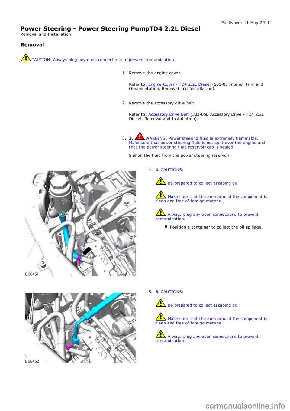
4. CAUTIONS:
Be prepared t o collect es caping oi l.
Make s ure that t he area around the component i sclean and free of foreign materi al.
Al ways pl ug any open connect ions t o preventcont ami nat ion.
Pos it ion a contai ner t o coll ect t he oil s pill age.
4.
5. CAUTIONS:
Be prepared t o collect es caping oi l.
Make s ure that t he area around the component i sclean and free of foreign materi al.
Al ways pl ug any open connect ions t o preventcont ami nat ion.
5.
Page 561 of 3229
Publi s hed: 11-May-2011
Power Steering - Power Steering Fluid Cooler
Removal and Inst all ati on
Removal
1. W ARNING: Do not work on or under a vehi cle s upported onl yby a jack. Al ways support t he vehi cl e on s afet y s tands .
Rais e and s upport t he vehi cl e.
1.
Remove t he front wheel s and ti res .
Refer t o: W heel and Ti re (204-04 W heel s and Tires, Removal andInst all at ion).
2.
Remove t he front bumper.
Refer t o: Front Bumper (501-19 Bumpers , Removal and Ins tall ati on).
3.
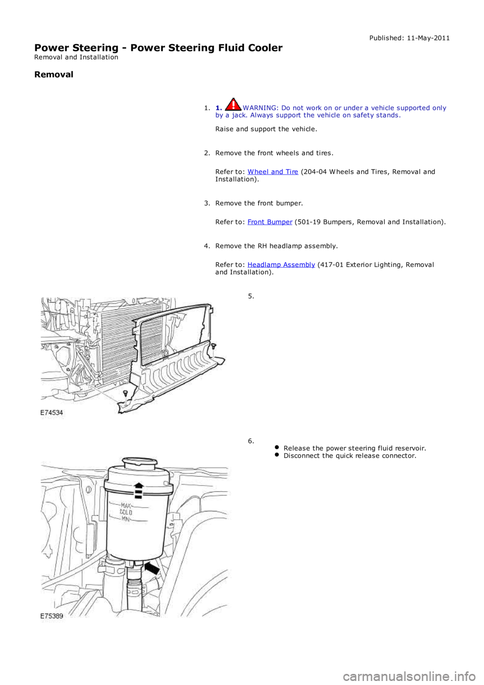
Remove t he RH headlamp as s embly.
Refer t o: Headl amp As sembl y (417-01 Ext eri or Li ght ing, Removaland Inst all at ion).
4.
5.
Releas e t he power s t eering flui d res ervoir.Di sconnect t he qui ck rel eas e connect or.
6.
Page 563 of 3229
Publi s hed: 11-May-2011
Power Steering - Power Steering Fluid Reservoir
Removal and Inst all ati on
Removal
Remove t he power s t eering flui d res ervoir cap.1.
Us ing a s ui table s yringe, remove t he power st eering fl ui d from thepower st eeri ng fl uid reservoi r.2.
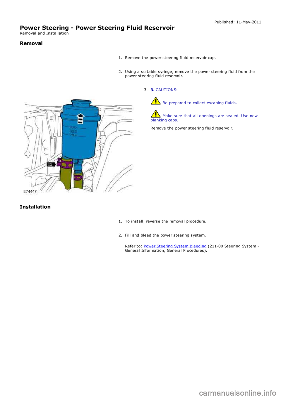
3. CAUTIONS:
Be prepared t o collect es caping flui ds .
Make s ure that all openings are sealed. Us e newblanking caps.
Remove t he power s t eering flui d res ervoir.
3.
Installation
To i nst all , revers e t he removal procedure.1.
Fil l and bl eed the power s t eering s ys tem.
Refer t o: Power St eering Sys tem Bleeding (211-00 St eering Sys tem -General Informat ion, General Procedures ).
2.
Page 2697 of 3229
Publ is hed: 11-May-2011
Uni-Body, Subframe and Mounting System - Front SubframeRemoval and Installation
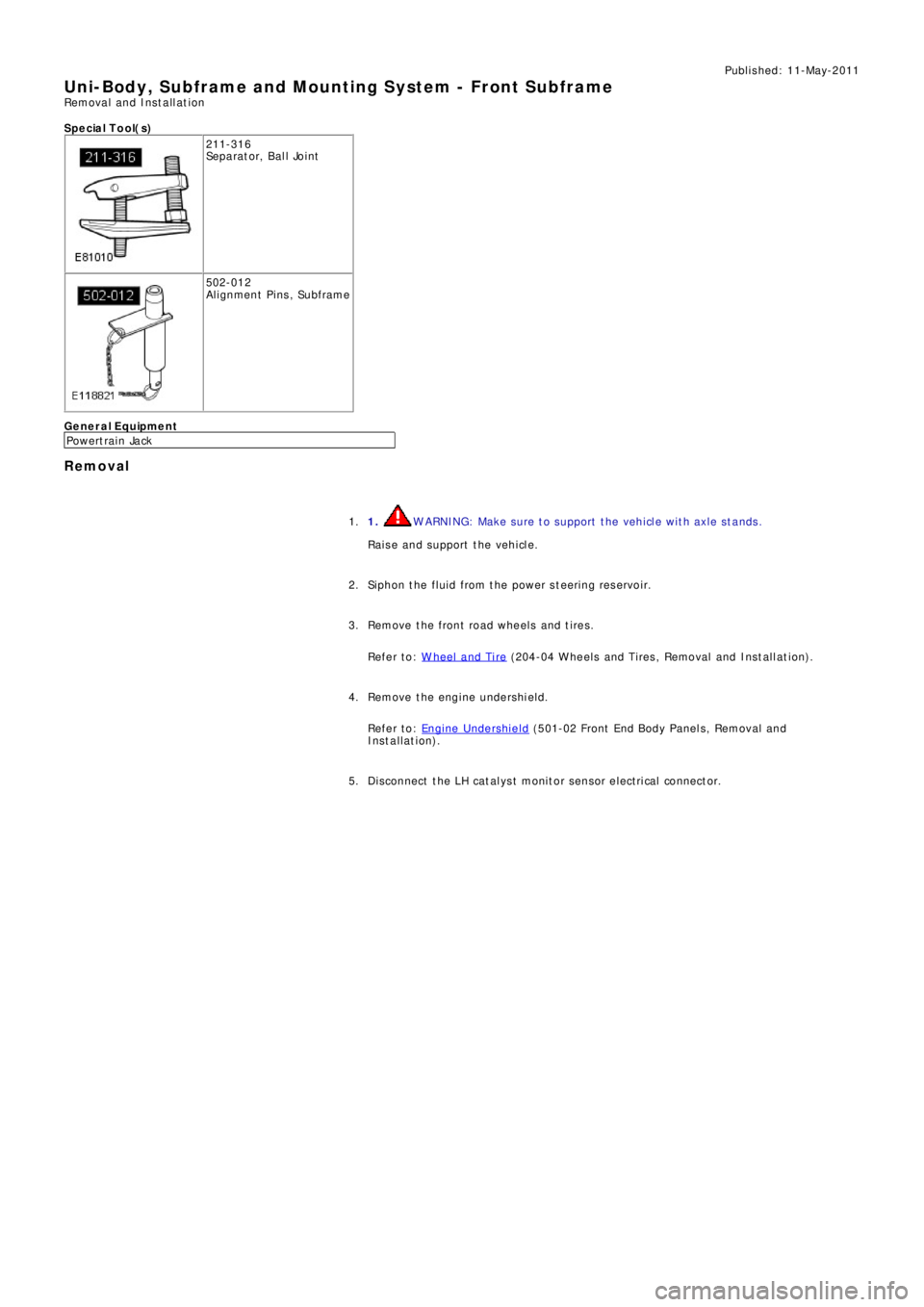
S p e c ia l T o o l( s )
211-316
Se p a ra t o r, B a l l Jo i nt
502-012
Alignment Pins, Subframe
General Equipment
P o we rt ra i n Ja ck
Removal
1. WARNING: Make sure to support the vehicle with axle stands.
Raise and support the vehicle. 1.
Siphon the fluid from the power steering reservoir. 2.
Remove the front road wheels and tires.
Refer to: W heel and Tire
(204-04 W heels and Tires , Removal and Ins t all at i on). 3.
Remove the engine undershield.
Refer to: Engine Undershield
(501-02 Front End Body Panel s, Removal and
Installation). 4.
Di sconnect t he LH cat al ys t monit or sens or elect ri cal connect or. 5.