Page 643 of 3229

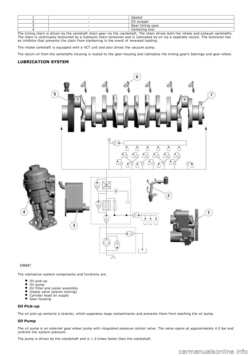
1-Gasket2-Oil s craper3-Rear t iming cas e4-Cent ering t oolThe t iming chain is driven by t he camshaft chain gear via t he cranks haft . The chain drives bot h t he int ake and exhaus t cams haft s.The chain is cont inually t ensioned by a hydraulic chain t ens ioner and is lubricated by oil via a separat e nozz le. The tensioner hasan inhibit or that prevent s t he chain from s lackening in t he event of revers ed loading.
The intake camshaft is equipped wit h a VCT unit and als o drives t he vacuum pump.
The return oil from t he cams hafts housing is rout ed t o t he gear hous ing and lubricates t he timing gear's bearings and gear wheel.
LUBRICATION SYSTEM
The lubricat ion sys tem component s and funct ions are:
O il pick-upO il pumpO il filter and cooler ass emblyIntake valve (pis t on cooling)Cylinder head oil supplyGear hous ing
Oil Pick-up
The oil pick-up contains a s t rainer, which s eparat es large cont aminant s and prevent s t hem from reaching t he oil pump.
Oil Pump
The oil pump is an external gear wheel pump wit h int egrat ed pres sure cont rol valve. The valve opens at approximat ely 4.5 bar andcont rols t he sys tem pres sure.
The pump is driven by t he cranks haft and is 1.3 t imes fast er t han t he crankshaft .
Page 644 of 3229

To ensure t hat the air is releas ed from t he oil sys tem, a valve is locat ed in t he oil pump on t he pres sure s ide. During t he build-upof press ure, air is routed out into the crankcas e. This cont inues unt il t he valve clos es at approximat ely 0.2 bar.
Oil Filter and Cooler Assembly
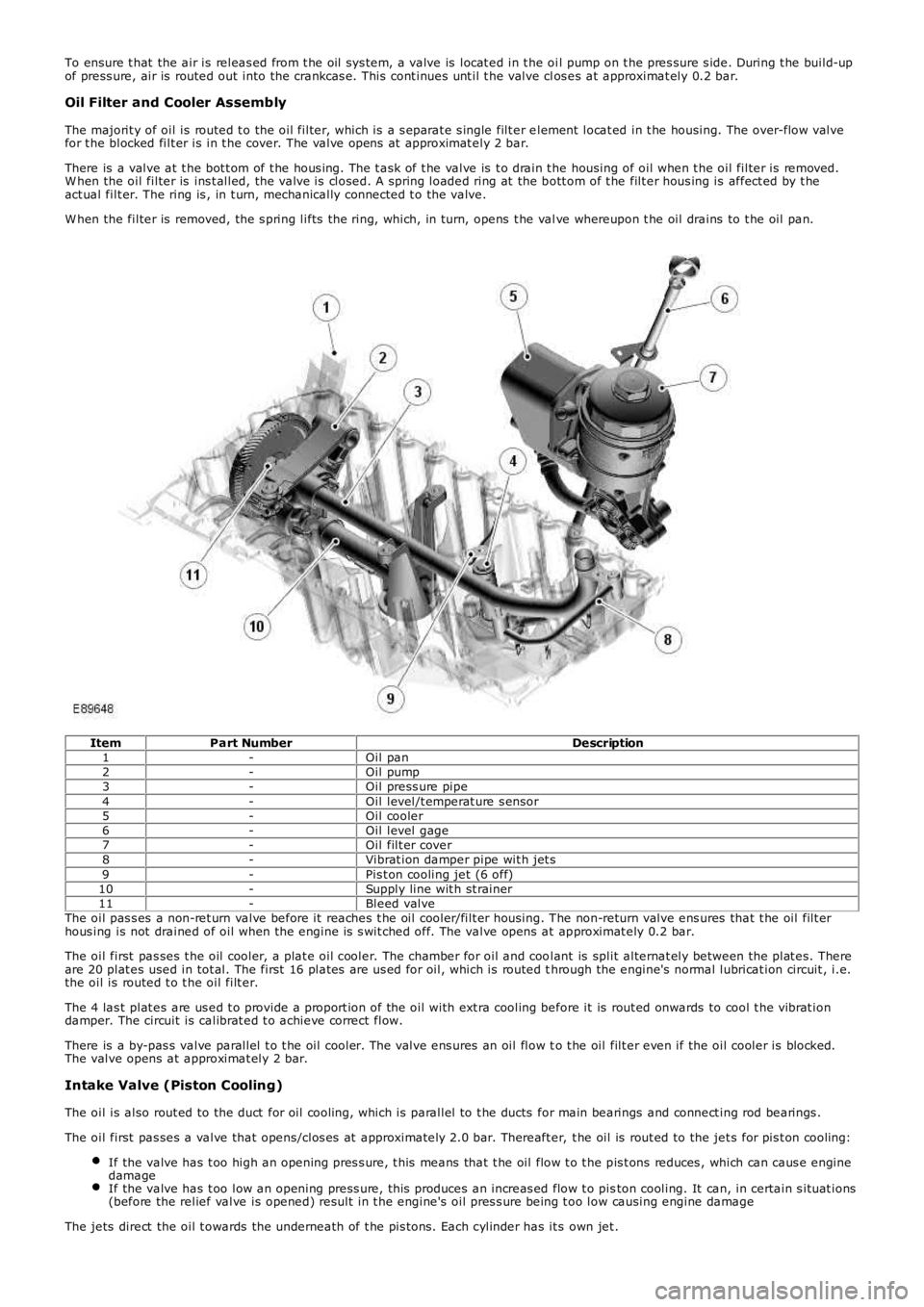
The majorit y of oil is routed t o the oil filter, which is a s eparat e s ingle filt er element locat ed in t he housing. The over-flow valvefor t he blocked filt er is in t he cover. The valve opens at approximat ely 2 bar.
There is a valve at t he bot t om of t he hous ing. The t ask of t he valve is t o drain t he housing of oil when t he oil filter is removed.W hen the oil filter is ins t alled, the valve is closed. A spring loaded ring at the bott om of t he filt er hous ing is affect ed by t heact ual filt er. The ring is , in t urn, mechanically connected t o the valve.
W hen the filter is removed, the s pring lifts the ring, which, in turn, opens t he valve whereupon t he oil drains to t he oil pan.
ItemPart NumberDescription1-Oil pan2-Oil pump3-Oil press ure pipe4-Oil level/t emperat ure s ensor5-Oil cooler6-Oil level gage7-Oil filt er cover8-Vibrat ion damper pipe wit h jet s9-Pis t on cooling jet (6 off)10-Supply line wit h st rainer11-Bleed valveThe oil pas s es a non-ret urn valve before it reaches t he oil cooler/filt er housing. The non-return valve ens ures that t he oil filt erhous ing is not drained of oil when the engine is s wit ched off. The valve opens at approximat ely 0.2 bar.
The oil first pas ses t he oil cooler, a plat e oil cooler. The chamber for oil and coolant is split alternat ely between the plat es. Thereare 20 plat es used in tot al. The first 16 plat es are us ed for oil, which is routed through the engine's normal lubricat ion circuit , i.e.the oil is routed t o t he oil filt er.
The 4 las t plat es are us ed t o provide a proport ion of the oil with ext ra cooling before it is rout ed onwards to cool t he vibrat iondamper. The circuit is calibrat ed t o achieve correct flow.
There is a by-pas s valve parallel t o t he oil cooler. The valve ens ures an oil flow to t he oil filt er even if the oil cooler is blocked.The valve opens at approximat ely 2 bar.
Intake Valve (Piston Cooling)
The oil is also rout ed to the duct for oil cooling, which is parallel to t he ducts for main bearings and connect ing rod bearings .
The oil first pas ses a valve that opens/clos es at approximately 2.0 bar. Thereaft er, t he oil is rout ed to the jet s for pis t on cooling:
If the valve has t oo high an opening pres s ure, t his means that t he oil flow t o t he pis t ons reduces , which can caus e enginedamageIf the valve has t oo low an opening press ure, this produces an increas ed flow t o piston cooling. It can, in certain s ituat ions(before the relief valve is opened) result in t he engine's oil pres s ure being t oo low causing engine damage
The jets direct the oil t owards the underneath of t he pis tons. Each cylinder has it s own jet .
Page 697 of 3229
Publi s hed: 11-May-2011
Engine - I6 3.2L Petrol - Oil Filter Element
Removal and Inst all ati on
Removal
Releas e t he PAS fl uid reservoi r from t he bracket and ti e as ide.
1. Loosen t he element cover 4 compl ete t urns t o al low
engine oil t o drai n from the fil ter cover.
2. 3.
Installation Inst all t he oil fi lt er element.
1.
Inst all t he engi ne oil filt er.
T orque: 25 Nm 2.
Secure t he res ervoir.
3.
Check and top-up the engine oi l.
4.
Page 766 of 3229
ItemPart NumberDescription
1-Bolt (7 off)2-Gas ket
3-Coolant pump
The engi ne cool ant pump is a cent ri fugal type, and is direct ly driven by t he t oot hed cams haft bel t. A s eal ing gas ket and 7bolt s s ecure the pump to the front RH si de of the cyli nder bl ock.For addit ional informat ion, refer t o: Engi ne Cooling (303-03B Engine Cooli ng - TD4 2.2L Dies el , Descripti on and Operat ion).
Oil Filter and Cooler Assembly
A combined engine oi l cooler and fil ter as sembl y is mount ed on t he LH s ide of t he engine block, in-line wit h No. 3 cylinder.The fi lt er hous ing contai ns a dis pos abl e paper fil ter element , and an oil pres s ure swi tch. For furt her i nformat ion, refer to'Lubri cat ion Sys tem' wi thin thi s s ect ion.
Counter-Balance Shaft Assembly
Page 800 of 3229

ItemPart NumberDescription
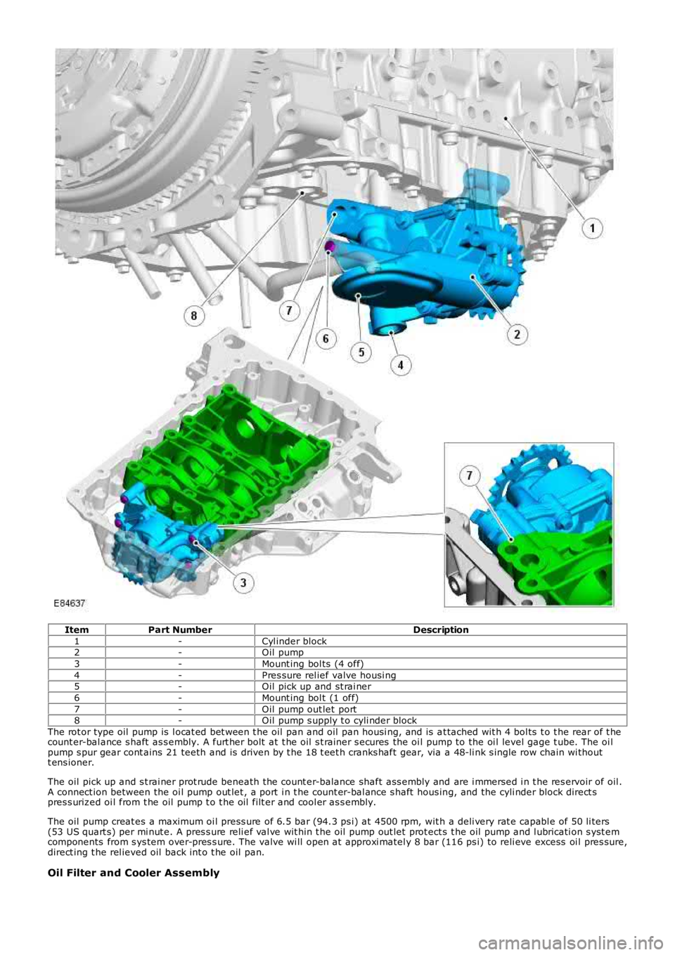
1-Cyl inder block2-Oil pump
3-Mount ing bol ts (4 off)
4-Pres sure rel ief valve housi ng5-Oil pick up and st rai ner
6-Mount ing bol t (1 off)
7-Oil pump out let port8-Oil pump s upply t o cyli nder block
The rot or type oil pump is l ocat ed bet ween t he oil pan and oil pan housi ng, and is at tached wit h 4 bol ts t o t he rear of t hecount er-bal ance s haft as s embly. A furt her bolt at t he oil s t rainer s ecures the oi l pump to the oi l level gage t ube. The oi lpump s pur gear cont ains 21 teeth and is driven by t he 18 t eet h cranks haft gear, via a 48-li nk s ingle row chain wi thoutt ens ioner.
The oil pick up and s t rai ner prot rude beneath the count er-balance shaft ass embly and are i mmersed i n t he res ervoir of oil .A connect ion between the oi l pump out let , a port i n t he count er-bal ance s haft hous ing, and the cyli nder block direct spres s urized oi l from t he oil pump t o t he oil filt er and cool er as s embly.
The oil pump creat es a maximum oi l press ure of 6.5 bar (94.3 ps i) at 4500 rpm, wit h a deli very rat e capabl e of 50 li ters(53 US quart s) per mi nut e. A pres s ure reli ef val ve wit hin t he oil pump out let prot ect s t he oil pump and l ubricati on s yst emcomponents from s ys tem over-pres s ure. The valve wi ll open at approxi matel y 8 bar (116 ps i) to reli eve excess oi l pres sure,direct ing t he rel ieved oil back int o t he oil pan.
Oil Filter and Cooler Assembly
Page 874 of 3229
Publi s hed: 11-May-2011
Engine - TD4 2.2L Diesel - Oil Filter Element
Removal and Inst all ati on
Removal
• NOTE: Removal s t eps in t his procedure may cont ain i nst all ati on det ail s.
1. W ARNING: Do not work on or under a vehi cle s upported onl y
by a jack. Al ways support t he vehi cl e on s afet y s tands .
Rais e and s upport t he vehi cl e.
1.
Remove t he engi ne undershi eld.
Refer t o: Engi ne Unders hi eld (501-02 Front End Body Panel s ,
Removal and Ins tall ati on).
2. 3. W ARNING: Fl uid l oss is unavoi dabl e, us e
abs orbent cl ot h or a contai ner t o coll ect t he fl uid.
• CAUTIONS: Make s ure that t he area around the component i s
clean and free of foreign materi al. Di s card the seal.
T orque: 25 Nm 3.
Installation To i nst all , revers e t he removal procedure.
1.
Check and top-up the engine oi l.
2.
Page 1233 of 3229
All vehicles
To i nst all , revers e t he removal procedure.1.
Vehicles with diesel particulate filter (DPF)
Renew t he engi ne oil and filt er.
Refer t o: Engi ne Oil Draining and Fi lli ng (303-01B Engi ne - TD4 2.2LDi es el, General Procedures ).
2.
All vehicles
If a new component has been ins t al led, configure usi ng Land Roverapproved diagnos t ic equipment .3.
Page 1268 of 3229
All vehicles
To i nst all , revers e t he removal procedure.
1.
Vehicles with diesel particulate filter (DPF) Renew t he engi ne oil and filt er.
Refer t o: Engi ne Oil Draining and Fi lli ng (303-01B Engi ne - TD4 2.2L
Di es el, General Procedures ).
2.
All vehicles If a new component has been ins t al led, configure usi ng Land Rover
approved diagnos t ic equipment .
3.