2006 LAND ROVER FRELANDER 2 climate control
[x] Cancel search: climate controlPage 1629 of 3229
Publi shed: 06-Jul-2011
Climate Control System - General Information - Climate Control System
Diagnosi s and Tes ti ng
Principles of Operation
For a detail ed descripti on of the cl imat e cont rol s yst em, refer to the relevant Des cri pti on and Operati on s ect ion i n t heworks hop manual . REFER to:
Air Dis t ri but ion and Fi lt ering (412-01 Cl imat e Control, Des cript ion and Operat ion),Heat ing and Vent il at ion (412-01 Cl imat e Control, Des cript ion and Operat ion),Air Condi ti oning (412-01 Cli mate Cont rol , Des cri pti on and Operati on),Cont rol Component s (412-01 Cli mate Cont rol , Des cri pti on and Operati on),Elect ric Boost er Heater (412-02B Auxi liary Cli mate Cont rol , Descri pti on and Operat ion),Fuel Fired Boos t er Heat er (412-02B Auxil iary Cli mate Cont rol, Des cri pt ion and Operati on).
Inspection and Verification
CAUTION: Di agnos is by s ubs ti tut ion from a donor vehicle is NO T acceptabl e. Subs ti tut ion of cont rol modules doesnot guarant ee confirmat ion of a faul t, and may als o caus e addit ional fault s i n t he vehi cl e being t est ed and/or t he donorvehi cl e.
1. Verify t he cus t omer concern.1.
2. Vis ually ins pect for obvious s igns of damage and s ys t em i ntegri ty.2.
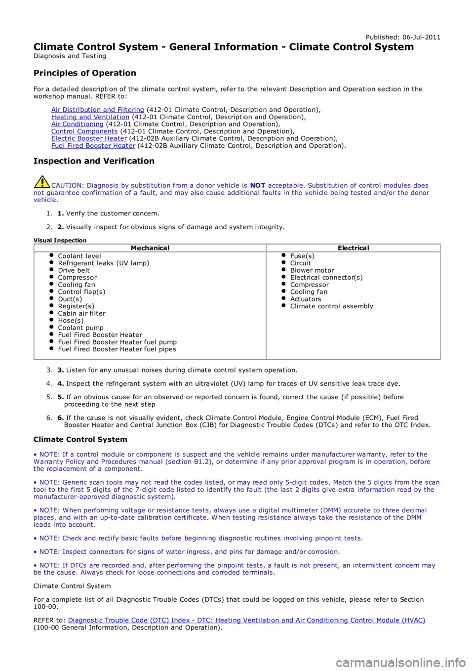
Visual InspectionMechanicalElectrical
Coolant levelRefrigerant l eaks (UV l amp)Drive beltCompres s orCooli ng fanControl flap(s)Duct(s )Regis ter(s )Cabin ai r fi lt erHos e(s )Coolant pumpFuel Fi red Boos ter HeaterFuel Fi red Boos ter Heater fuel pumpFuel Fi red Boos ter Heater fuel pipes
Fus e(s)Circui tBlower mot orElectrical connect or(s)Compres s orCool ing fanAct uatorsCli mate cont rol ass embly
3. Lis ten for any unus ual noi ses during cli mate cont rol s ys t em operat ion.3.
4. Ins pect t he refri gerant s ys t em wi th an ult raviolet (UV) lamp for t races of UV s ens i ti ve leak t race dye.4.
5. If an obvious cause for an obs erved or report ed concern is found, correct t he caus e (if pos s ible) beforeproceeding t o t he next s t ep5.
6. If t he caus e is not vis ually evi dent , check Cli mate Cont rol Module, Engi ne Control Module (ECM), Fuel FiredBoos ter Heater and Central Juncti on Box (CJB) for Di agnos ti c Trouble Codes (DTCs ) and refer to the DTC Index.6.
Climate Control System
• NOTE: If a cont rol module or component i s s uspect and the vehicl e remai ns under manufacturer warrant y, refer t o t heW arranty Pol icy and Procedures manual (s ect ion B1.2), or determine i f any pri or approval program is i n operat ion, beforet he replacement of a component.
• NOTE: Generic scan t ool s may not read the codes li st ed, or may read only 5-digi t codes . Match t he 5 digi ts from t he s cant ool t o t he fi rs t 5 di gi ts of the 7-digit code li s ted t o i dent ify the fault (the last 2 digi ts gi ve ext ra informati on read by themanufacturer-approved di agnos ti c s ys t em).
• NOTE: W hen performing volt age or res is t ance t est s , always use a digi tal mult imeter (DMM) accurat e t o t hree deci malplaces, and wi th an up-t o-date cal ibrat ion cert ificate. W hen tes ti ng res is t ance al ways take t he res is t ance of t he DMMleads i nt o account .
• NOTE: Check and recti fy bas ic faul ts before beginni ng diagnos t ic rout ines i nvol vi ng pinpoint t es t s.
• NOTE: Ins pect connect ors for s igns of water ingres s , and pins for damage and/or corros ion.
• NOTE: If DTCs are recorded and, aft er performi ng the pi npoi nt tes ts , a fault is not present , an int ermi tt ent concern maybe t he caus e. Always check for loose connect ions and corroded terminals .
Cli mate Cont rol Syst em
For a compl ete lis t of all Di agnos ti c Trouble Codes (DTCs) t hat could be logged on this vehicle, pleas e refer to Sect ion100-00.
REFER to: Di agnos ti c Trouble Code (DTC) Index - DTC: Heati ng Vent il ati on and Air Condit ioning Control Modul e (HVAC)(100-00 General Informati on, Des cri pti on and Operati on).
Page 1630 of 3229
Publi s hed: 11-May-2011
Climate Control System - General Information - Air Conditioning (A/C)
System Recovery, Evacuation and Charging
General Procedures
1. W ARNING: Servicing mus t be carried out by pers onnelfamil liar wi th bot h vehicle s ys tem and the chargi ng and tes t ingequipment. Al l operat ions mus t be carried out i n a wel l vent ilat edarea away from open flame and heat s ources .
• NOTE: The receiver dri er need onl y be changed under t he followi ngcircums t ances : There i s dirt in t he refri gerant ci rcuit ( eg.compres s or s eizure ), t he s yst em is l eaking and refrigerant has beenl os t t o at mosphere, or t he refri gerant ci rcuit has been open moret han 24 hours , due to repair.
Refrigerant recovery and recycle.
1.
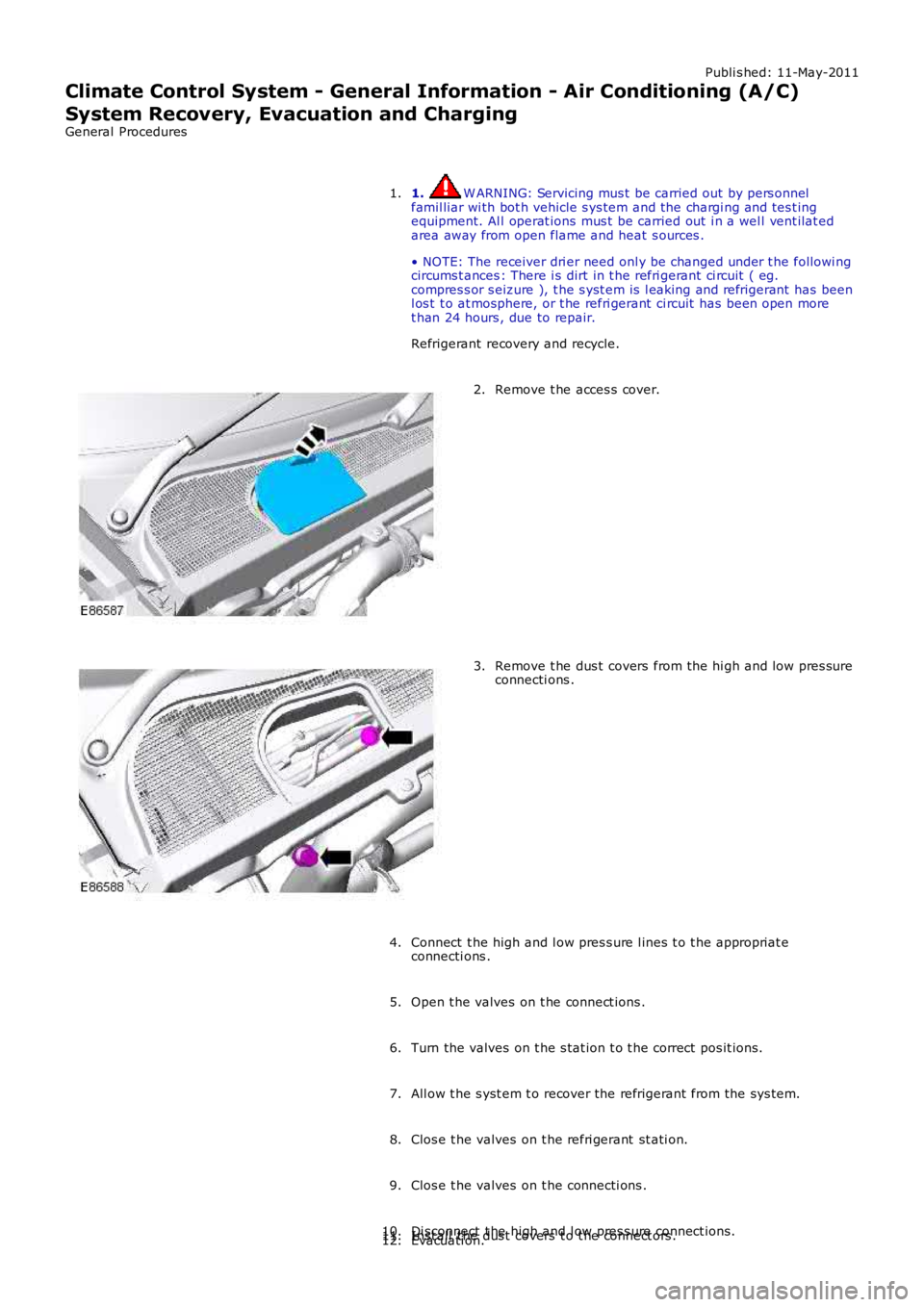
Remove t he acces s cover.2.
Remove t he dus t covers from the hi gh and low pres sureconnecti ons .3.
Connect t he high and l ow pres s ure l ines t o t he appropriat econnecti ons .4.
Open t he valves on t he connect ions .5.
Turn the valves on t he s tat ion t o t he correct pos it ions.6.
All ow t he s yst em t o recover the refrigerant from the sys tem.7.
Clos e t he valves on t he refri gerant st ati on.8.
Clos e t he valves on t he connecti ons .9.
Di sconnect t he high and l ow pres s ure connect ions.10.Inst all t he dus t covers t o t he connect ors .11.Evacuati on.12.
Page 1632 of 3229
Publi s hed: 11-May-2011
Climate Control -
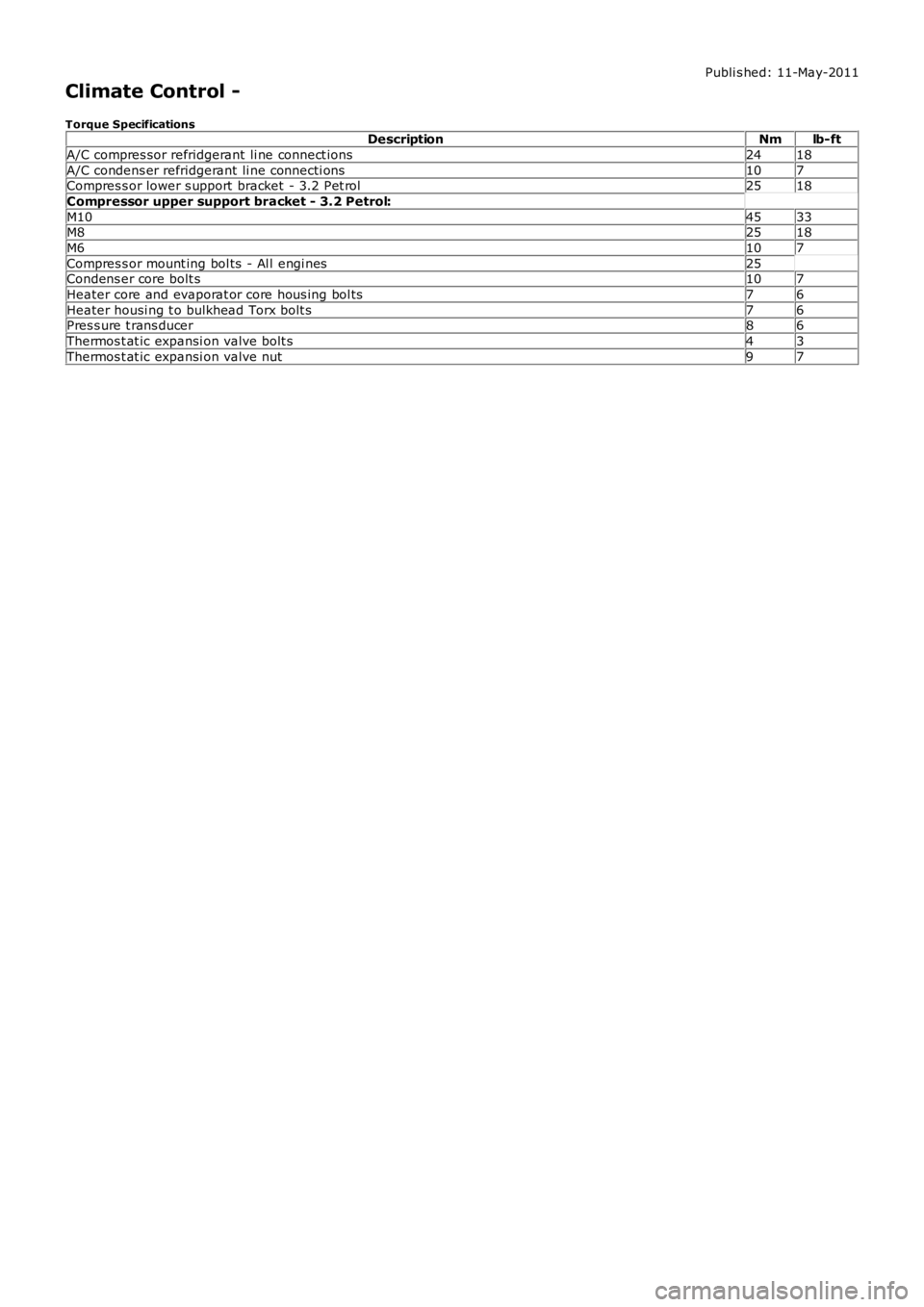
Torque SpecificationsDescriptionNmlb-ft
A/C compres sor refridgerant li ne connect ions2418
A/C condens er refridgerant li ne connecti ons107Compres s or lower s upport bracket - 3.2 Pet rol2518
Compressor upper support bracket - 3.2 Petrol:
M104533M82518
M6107
Compres s or mount ing bol ts - Al l engi nes25Condens er core bolt s107
Heater core and evaporat or core hous ing bol ts76
Heater housi ng t o bulkhead Torx bolt s76Pres s ure t rans ducer86
Thermos t at ic expansi on valve bolt s43
Thermos t at ic expansi on valve nut97
Page 1633 of 3229
Publi s hed: 11-May-2011
Climate Control - Air Distribution and Filtering
Des cript ion and Operat ion
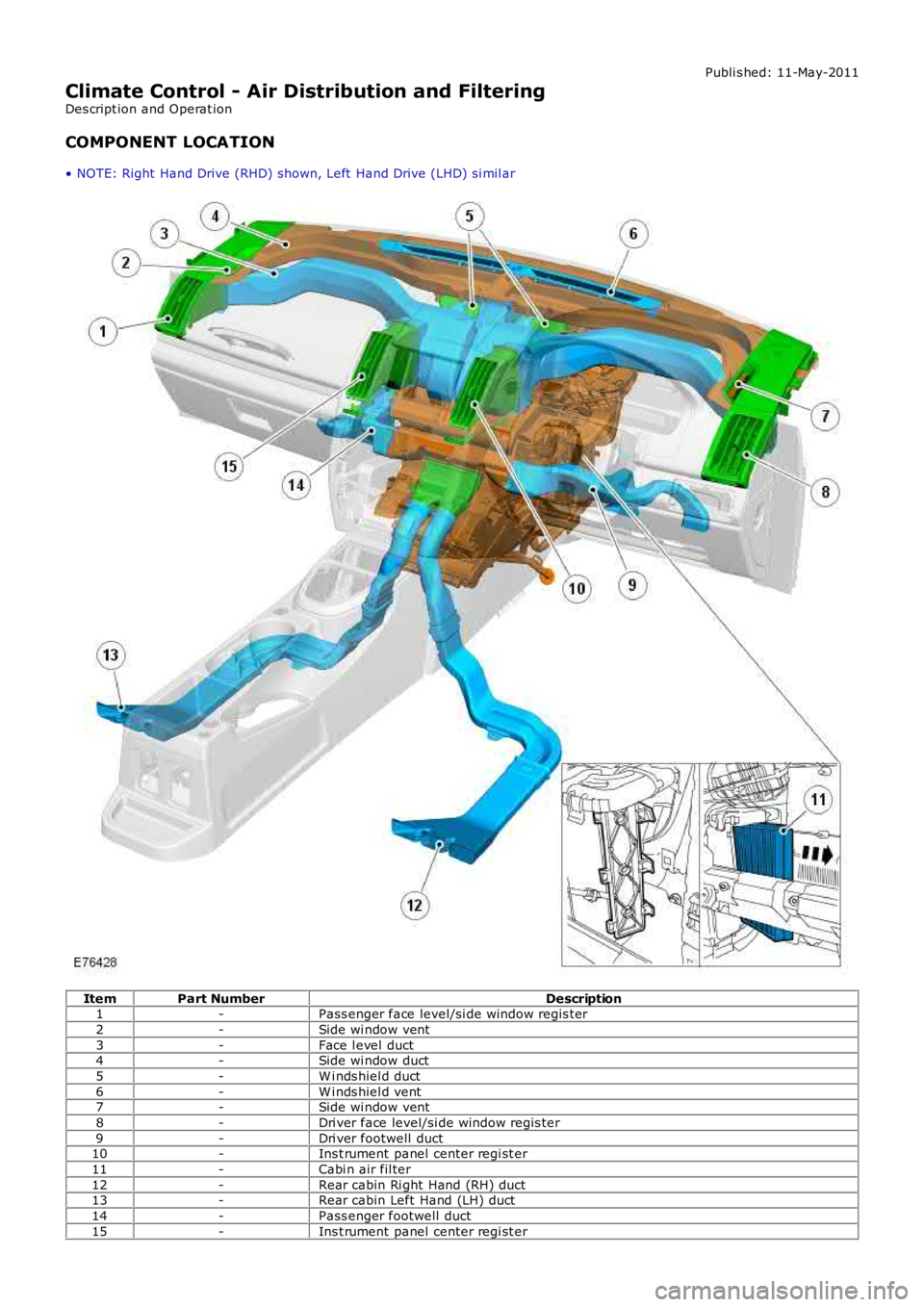
COMPONENT LOCATION
• NOTE: Right Hand Drive (RHD) shown, Left Hand Drive (LHD) si mil ar
ItemPart NumberDescription1-Pass enger face level/si de window regis ter
2-Side wi ndow vent
3-Face l evel duct4-Side wi ndow duct
5-W i nds hiel d duct
6-W i nds hiel d vent7-Side wi ndow vent
8-Dri ver face level/si de window regis ter
9-Dri ver footwell duct10-Ins t rument panel center regi st er
11-Cabi n air fil ter
12-Rear cabin Ri ght Hand (RH) duct13-Rear cabin Left Hand (LH) duct
14-Pass enger footwell duct
15-Ins t rument panel center regi st er
Page 1635 of 3229
Publi s hed: 11-May-2011
Climate Control - Heating and Ventilation
Des cript ion and Operat ion
COMPONENT LOCATION
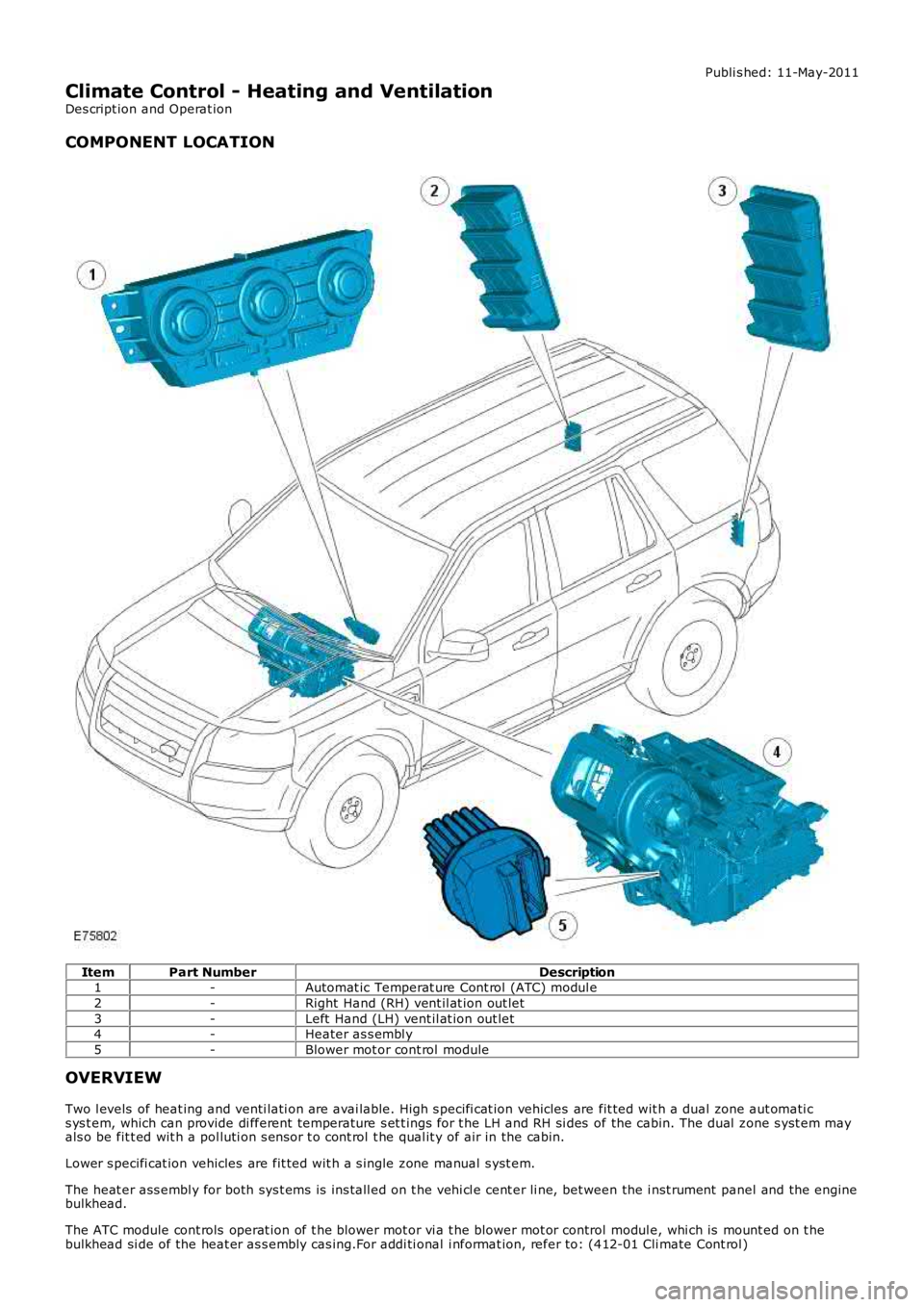
ItemPart NumberDescription1-Automat ic Temperat ure Cont rol (ATC) modul e
2-Right Hand (RH) vent il at ion out let
3-Left Hand (LH) vent il at ion out let4-Heater as s embl y
5-Blower mot or cont rol module
OVERVIEW
Two l evels of heat ing and venti lati on are avai lable. High s pecifi cat ion vehicles are fit ted wit h a dual zone aut omati cs ys t em, which can provide di fferent temperature s et t ings for t he LH and RH si des of the cabin. The dual zone s yst em mayals o be fit t ed wit h a pol luti on s ens or t o cont rol t he qual it y of air in the cabin.
Lower s pecifi cat ion vehicles are fit ted wit h a s ingle zone manual s yst em.
The heat er ass embl y for both sys t ems is ins tall ed on t he vehi cl e cent er li ne, bet ween the i nst rument panel and the enginebulkhead.
The ATC module cont rols operat ion of t he blower mot or vi a t he blower mot or control modul e, whi ch is mount ed on t hebulkhead si de of the heat er as s embly cas ing.For addi ti onal i nformat ion, refer to: (412-01 Cli mate Cont rol )
Page 1638 of 3229
Publi s hed: 11-May-2011
Climate Control - Air Conditioning
Des cript ion and Operat ion
COMPONENT LOCATION
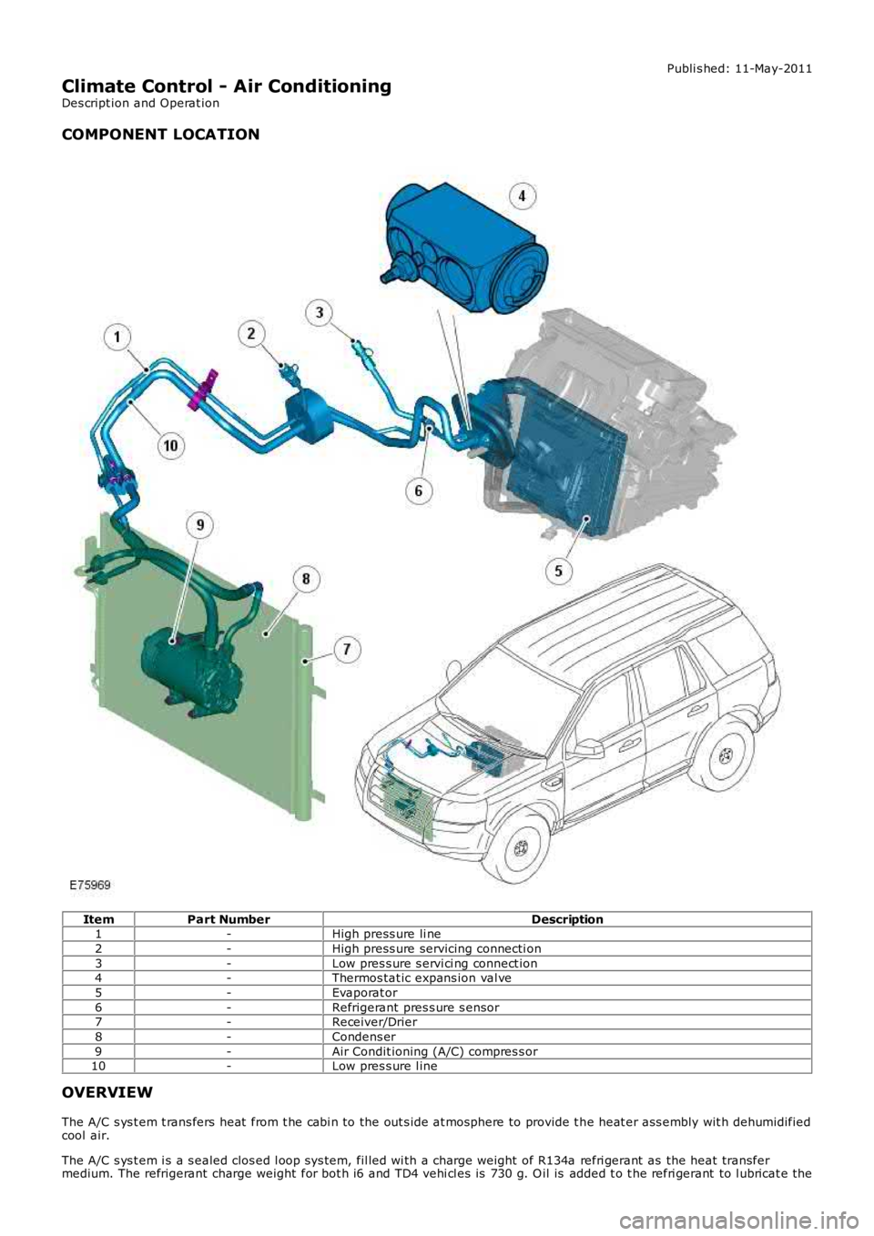
ItemPart NumberDescription1-High press ure li ne
2-High press ure servicing connecti on
3-Low pres s ure s ervi ci ng connect ion4-Thermos tat ic expans ion val ve
5-Evaporat or
6-Refrigerant pres s ure s ensor7-Receiver/Drier
8-Condens er
9-Air Condit ioning (A/C) compres s or10-Low pres s ure l ine
OVERVIEW
The A/C s ys t em t rans fers heat from t he cabi n to the out s ide at mosphere to provide t he heat er ass embly wit h dehumidifiedcool air.
The A/C s ys t em i s a s ealed clos ed l oop sys tem, fil led wi th a charge weight of R134a refri gerant as the heat transfermedium. The refrigerant charge weight for bot h i6 and TD4 vehi cl es is 730 g. O il is added t o t he refri gerant to l ubricat e the
Page 1644 of 3229
Publishe d: 11-May-2011
Climate Control - Control ComponentsDescripti on a nd O pe ration
COMPONENT LOCATION
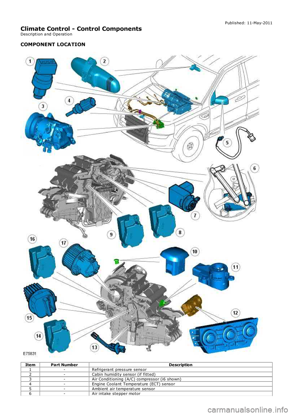
ItemPart NumberDe scription1-Refrigera nt press ure sens or2-Cabin humidi ty s ensor (if fitt ed)3-Air Condi tioning (A/C) compressor (i6 shown)4-Engine Coola nt Temperat ure (ECT) s ensor5-Ambi ent air t emperat ure sensor6-Air intake ste ppe r motor
Page 1645 of 3229
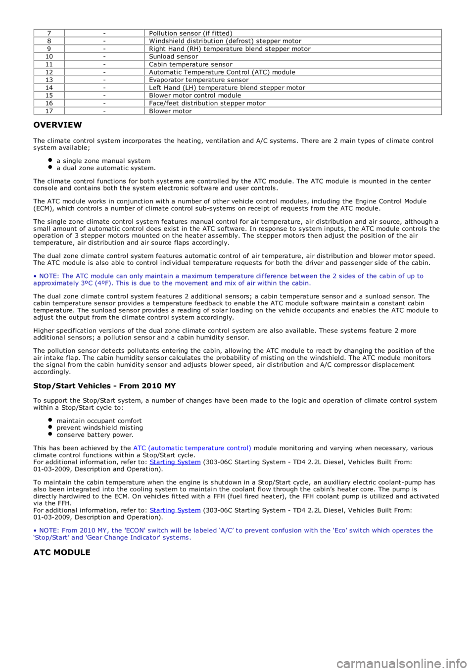
7-P ollution sensor (if fi tted)8-W indshie ld distri buti on (defrost) ste pper motor9-Right Hand (RH) tempera ture ble nd s tepper mot or10-Sunload s ens or11-Cabin temperature se nsor12-Automati c Te mpe rature Cont rol (ATC) modul e13-Evaporator te mpe rature s ens or14-Left Hand (LH) te mpe rature blend st eppe r motor15-Blowe r motor control module16-Face/feet dis tribution ste ppe r motor17-Blowe r motor
OVERVIEW
The clima te cont rol s yste m i ncorpora tes the hea ting, ve ntila tion and A/C systems. There are 2 mai n types of clima te controls yste m a vail able ;
a single z one ma nual sys tema dua l zone a utomati c system.
The clima te cont rol f unct ions for bot h systems a re controlle d by the ATC modul e. The ATC module is mounted in the ce nte rcons ole a nd cont ains bot h the syste m e lectronic sof twa re a nd user cont rols .
The ATC module works in conjunction wi th a number of othe r ve hicle control module s, i ncluding the Engine Control Module(ECM), which control s a number of cl ima te control sub-s yste ms on recei pt of reques ts f rom the ATC module .
The s ingle zone climate cont rol s yst em f eat ures ma nual control for air t empera ture , air dist ribution and air source, although as mal l amount of aut oma tic control does exis t in the ATC softwa re. In re sponse to s yste m i nput s, t he ATC module cont rols theopera tion of 3 st epper motors mounted on t he heat er as sembly. The st eppe r motors then a djust the positi on of the ai rt emperat ure, air dist ribution and air source flaps accordingly.
The dual zone cl imat e control system fe atures a utomati c control of air t empera ture , air dis tribution and blower motor s pee d.The ATC module is a lso able to cont rol i ndividua l te mpe rature re que sts for both the dri ver a nd pass enger s ide of the cabin.
• NO TE: The ATC module can only maint ain a maximum tempera ture dif fere nce bet wee n the 2 side s of the cabin of up toa pproximate ly 3ºC (4ºF). This is due to the moveme nt a nd mix of a ir wi thin the cabin.
The dual zone cl imat e control system fe atures 2 additional sens ors; a cabin temperature se nsor and a sunload sensor. Thecabin temperature se nsor provides a temperature fe edback to e nabl e the ATC module s oftware mai ntai n a cons tant ca bint emperat ure. The sunloa d se nsor provide s a rea ding of s ola r loa ding on the vehicle occupants a nd enables the ATC module toa djus t the output from t he clima te control s yste m a ccordingly.
Higher specif icat ion vers ions of t he dual zone cl imat e control system are al so a vailable . These syst ems fea ture 2 morea ddit iona l se nsors; a polluti on s ensor and a cabin humidity sensor.
The pollution sensor det ects pol luta nts ente ring the cabin, allowing the ATC modul e to rea ct by cha ngi ng t he posit ion of thea ir intake fla p. The cabin humidi ty s ensor ca lcul ates the probability of misti ng on the winds hiel d. The ATC module monitorst he s igna l from t he cabin humidi ty s ensor and a djus ts blowe r speed, air dis tribution and A/C compress or di spla cementa ccordingly.
Stop/Start Vehicles - From 2010 MY
To support the Stop/Start system, a number of changes have be en made to the logic and opera tion of climate cont rol s yst emwithi n a Stop/Sta rt cycle to:
maint ain occupant comfortpreve nt winds hie ld mistingconse rve batt ery power.
This has bee n achieved by the ATC (automa tic t emperat ure control) module monitoring and varying when nece ssary, va riousclima te control funct ions wit hin a St op/Start cycle.For a ddit iona l inf ormation, re fer to: Starting Sys tem (303-06C Start ing Syst em - TD4 2.2L Diese l, Vehicles Buil t From:01-03-2009, Des cript ion and Ope rati on).
To maint ain the cabi n te mpe rature when the engine is s hut down in a St op/Start cycle, an a uxil iary electric coolant-pump hasa lso bee n int egra ted into the cooling system to mai ntai n the coolant flow t hrough t he cabi n’s heat er core. The pump isdirectly hardwire d to the ECM. O n ve hicl es fi tted wit h a FFH (fue l fired heat er), the FFH coolant pump i s uti lize d and activa tedvia t he FFH.For a ddit iona l inf ormation, re fer to: Starting Sys tem (303-06C Start ing Syst em - TD4 2.2L Diese l, Vehicles Buil t From:01-03-2009, Des cript ion and Ope rati on).
• NO TE: From 2010 MY , the 'ECO N' s witch will be la bele d ‘A/C’ t o prevent confusion wit h the ‘Eco’ s witch which ope rate s the‘Stop/Sta rt’ a nd 'Gea r Change Indica tor' syst ems .
ATC MODULE