2006 LAND ROVER FRELANDER 2 auxiliary battery
[x] Cancel search: auxiliary batteryPage 1754 of 3229
s tart fail ure or flameout, and decreas ed by one if a subs equent s tart is succes s ful . If t he event t imer i ncreas es t ot hree (over any number of drive cycl es), the cont rol module ent ers t he error lockout mode.Heat exchanger casing overheat: To prot ect t he s ys t em from exces s ive t emperatures , t he cont rol module ent erst he error l ockout mode if t he heat exchanger coolant temperat ure exceeds 125 °C (257 °F).Battery voltage out of limits: Error lockout wi ll occur if bat tery vol tage fall s bel ow 10.25 or ris es above 15.5 volt s .
The error lockout mode can be cleared usi ng the Land Rover approved di agnos ti c s ys t em, or by dis connect ing the bat terypower supply for a mi nimum of 10 s econds.
Remote Operation - Vehicles from 2009MY with FFBH Remote Control
The 868.3 MHz Radi o Frequency (RF) si gnal s t ransmit ted by the remote hands et are recei ved by the DAB/FFBH ant ennalocated i n t he LH rear s i de window. The s ignal s received by t he antenna are detected by t he FFBH receiver. A 'handshake's ignal is s ent back from the recei ver t o t he hands et t o confirm a val id on or off reques t and act ivate the handset LEDaccordi ngl y. The recei ver proces s es the s i gnal it recei ved and trans mi ts the appropriate si gnal s via a dedi cat ed bus t o theFFBH cont rol module.
• NOTE: The ‘handshake’ si gnal only confi rms hands et-receiver communi cat ions were s uccess ful , and not that t he FFBH hast urned on.
W hen t he FFBH is act ivated by the remote hands et, t he FFBH cont rol module will al low t he FFBH t o operate for 30 minutesor unt il an off request is received from t he remot e hands et or CJB. During t he 30 minut e period, the FFBH may operat e i neit her full l oad combus ti on, part load combus t ion or a controll ed idle phas e of operat ion, depending on t he t emperature oft he coolant i n t he heat exchanger.
Pre-burn Thresholds
The FFBH unit wi ll only acti vat e remotely if t he fol lowing thres hold condit ions are met:
Pre-burn batt ery vol tage check: ≥11.5V (volt age at FFBH terminals )Pre-burn coolant temperat ure check: ≤15°C (int ernal FFBH measurement )Pre-burn fuel l evel check: ≥7.5 lit ers (value s t ored i n FFBH at ignit ion off)
The fuel level val ue s tored wit hin t he FFBH unit i s only updated when t he engine i s running. W hen s t art ing t he FFBH viaremot e control wit h the engi ne off, the fuel l evel value us ed in the FFBH calculat ions wi ll be t hat s t ored at t he las t key offevent . It i s t herefore poss ibl e for t he FFBH t o fai l to operat e remotel y if t he engine was s t opped wi th a low fuel level; i ft he fuel tank i s s ubs equent ly refuell ed, the FFBH s t ored fuel l evel wil l st il l read l ow i f the engine has not been s tarteds ince refuel li ng.
If the FFBH does not act ivate due to low bat tery vol tage or l ow fuel l evel, t he FFBH cont rol module transmit s a mes s age ispass ed on t he medi um and high speed CAN bus es, vi a t he CJB to the i nst rument clus ter mes s age cent er which wil l dis playone of the foll owing mes s ages at i gnit ion on:
AUXILIARY HEATER UNAVAILABLE LOW FUELAUXILIARY HEATER UNAVAILABLE LOW BATTERY .
If bot h l ow fuel and low batt ery volt age mes sages are val id, t he ins trument cl ust er mes sage center wi ll alt ernate bet weent he two mes sages .
Remote Control ‘Park Heat’ to ATC ‘Supplementary Heat’ Transitions
• NOTE: The FFBH can s ti ll be acti vat ed by t he ATC module as previ ous l y descri bed
If the FFBH has been operated remot el y (‘park heat’) and the vehicl e is st art ed whilst the FFBH i s s ti ll act ive, it willt ransi ti on int o t he ATC-control led ‘s upplement ary heat’ mode if t he ATC request s i t.
Shoul d t he ATC t hen send a mess age t o t he FFBH to turn off, the FFBH will remain active if 30 minut es has not yetelaps ed from t he ori ginal remot e cont rol ‘park heat ’ request . Once t he remai nder of 30 mi nut es has elaps ed, t he FFBH wil lt urn off.
Swit chi ng Point Temperatures
W hen remotel y s tarted t he FFBH us es a different s et of s wit chi ng poi nt temperat ures t o t he normal ‘supplement al heat’mode. Thi s is because the remot e s tart feature can s tart the FFBH wi th the engine off – t hus different t hres hol ds arerequired t o opti mis e t he heati ng of the engine coolant.
Swit chi ng Point Temperatures
Page 1794 of 3229
MessageO ther WarningsReasonAction
Descripti on and Operat ion).
AUXILIARY HEATERUNAVAILABLE LOW FUEL(vehi cl es from 2009MYwi th Fuel Fired Boos t erHeater (FFBH))
NoneFuel l evel in fuel tank i s at or bel owthreshold when FFBH 'ON' reques t is made.Repl eni sh fuel in fuel tank
AUXILIARY HEATERUNAVAILABLE LOWBATTERY (Vehicles from2009MY wit h FFBH)
NoneBatt ery volt age is bel ow t hres hol d whenFFBH 'ON' reques t is made.Invest igat e reas on for l owbat tery volt age. Follow theprocedures i n t he Batt eryCare Manual t o es t abl is hthe condi ti on of thebat tery.
TRIP COMPUTER
Tri p comput er informat ion i s s hown in t he bott om hal f of the mes s age cent er when the s creen i s in dis play mode 3.
Trip Meter
A microprocess or in the ins trument cl us t er calculat es the trip dat a based on a wheel speed s ignal broadcas t by t heAnti -l ock Brake Sys t em (ABS) modul e over the hi gh speed CAN bus . The CJB act s as a gat eway and t ransmit s t he wheels peed si gnal t o t he ins trument cl ust er over t he medium s peed CAN bus .
The t rip meter di spl ays t he dis t ance t he vehicle has t raveled s i nce t he l as t t ri p met er res et . The t ri p met er can be reset bypres s ing and holdi ng the t rip computer butt on for more t han 1 s econd. The t ri p met er can dis play up to a dis t ance of 999.9mi les or kil omet ers . W hen this fi gure is exceeded the t ri p met er st art s again from 0 miles or ki lometers .
The t rip dat a i s s tored in the i nst rument clus t er Random Acces s Memory (RAM) and will be los t if t he batt ery i sdis connected.
Average Fuel Consumption
The ins t rument clus ter receives 2 fuel t ank level readings on t he medium s peed CAN bus vi a t he CJB. The i nst rumentclus ter calcul ates an average value of t he amount of usable fuel in the t ank from t he 2 s i gnal s. Every 200 meters ofvehi cl e t ravel the i nst rument clus t er re-calculat es this val ue to det ermine how much fuel has been us ed. Thi s value i s thenaveraged over t he las t 31 mi les (50 kil ometers ) of t ravel and di s pl ayed in t he t ri p comput er.
The dis t ance t raveled s ignal ori gi nates i n t he ABS module and i s received by t he inst rument clus ter over t he medi ums peed CAN bus via t he CJB.
Range
The range value i s calculated us i ng the average fuel cons umpt ion val ue (s ee above) and t he fuel t ank level val ue. Bydividi ng the fuel tank l evel val ue by t he average fuel cons umpti on value t he ins t rument clus ter can cal cul at e t he dis t ancet he vehi cl e can travel wi th the current amount of us abl e fuel i n t he tank before refil li ng is necess ary.
Average Speed
The average s peed s i gnal is cal cul at ed us ing t he vehi cle s peed s ignal s uppli ed by the CJB over the medium speed CANbus. This si gnal originat es in t he ABS module and is an average of t he 4 wheel s peed si gnal s. This val ue is di vided by t het ime si nce the l ast t ri p computer res et t o cal cul ate the average vehicle s peed.
ODOMETER
The odometer is locat ed i n the speedometer and dis plays t he tot al di s tance the vehicl e has travel ed. This is calculat edus ing t he s ame s ignal as that us ed for t he trip meter.
The odometer dis play can s how 6 characters and dis t ances up t o 999,999 mi les or kil ometers . The value i s s tored in aprot ect ed area of t he ins t rument clus ters Electroni cal ly Eras able Programmabl e Read Only Memory (EEPROM) every 1.2mi les (2 kil ometers ) of vehicle t ravel. W hen the i gnit ion i s s wit ched off, back up odomet er val ues are al so s tored in t hefol lowing modul es:
CJBABS moduleECMRest rai nts Cont rol Modul e (RCM)Dri ver door modulePass enger door module.
The odometer values in thes e modules are s ent t o t he ins t rument clus ter over t he medi um s peed CAN bus wit hin the firs t2 s econds of t he vehi cl e entering power mode 6. If the values received are t he s ame, t he clus ter det ermi nes t he odometervalue has not been tampered wit h. If any value i s outs ide of a 186 mil e (300 ki lometer) wi ndow the i nst rument clus t ers tores a Diagnos ti c Trouble Code (DTC) and wil l di spl ay the majori ty val ue. The DTC can be ret rieved us ing t he Land Roverapproved diagnos t ic s yst em.
Vehicle Operating Modes
The vehi cl e has 4 operat ing modes , which al low cert ain features to be enabl ed and dis abl ed:
Normal (nor)Fact ory (fact )Trans port (trans p)Cras h (cras h)
Page 2830 of 3229
Convenience features
110
L
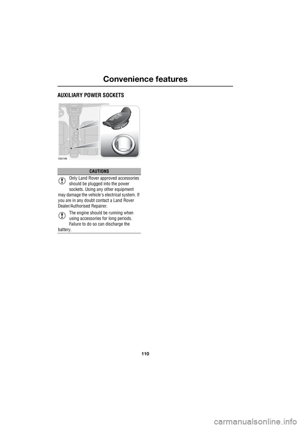
AUXILIARY POWER SOCKETS
CAUTIONS
Only Land Rover approved accessories
should be plugged into the power
sockets. Using any other equipment
may damage the vehicle's electrical system. If
you are in any doubt contact a Land Rover
Dealer/Authorised Repairer.
The engine should be running when
using accessories for long periods.
Failure to do so can discharge the
battery.
E82166
Page 2991 of 3229

Index
271
R
A
ABS driving hints . . . . . . . . . . . . . . . . . . 123
Accessories . . . . . . . . . . . . . . . . . . . . . . . . 37
Adaptive front lighting system (AFS). . . . . 74
Adjusting the headlamps . . . . . . . . . . . . . . 73
Adjusting the steering wheel . . . . . . . . . . . 70
Adjusting the windscreen washer jets . . . . 89 Blocked jets . . . . . . . . . . . . . . . . . . . . . 90
Front . . . . . . . . . . . . . . . . . . . . . . . . . . . 89
Rear . . . . . . . . . . . . . . . . . . . . . . . . . . . 89
AFS . . . . . . . . . . . . . . . . . . . . . . . . . . . . . . 74
Air vents . . . . . . . . . . . . . . . . . . . . . . . . . 101
Airbag service information . . . . . . . . . . . . 63
Airbag warning lamp . . . . . . . . . . . . . . . . . 61
Alternative frequencies . . . . . . . . . . . . . . 229
Alternative Frequency (AF) - Premium audio 230
Alternative Frequency (A F) - Standard audio
230
Approach lamps . . . . . . . . . . . . . . . . . . . . 76
Arming the alarm . . . . . . . . . . . . . . . . . . . 45
Alarm indicator . . . . . . . . . . . . . . . . . . . 45
Full alarm . . . . . . . . . . . . . . . . . . . . . . . 45
Partial alarm . . . . . . . . . . . . . . . . . . . . . 45
Ashtray . . . . . . . . . . . . . . . . . . . . . . . . . . 109
Audio control. . . . . . . . . . . . . . . . . . . 70, 223 Audio control using the telephone buttons .
71
Balance adjustment. . . . . . . . . . . . . . . 224
Bass response adjustment . . . . . . . . . 223
Centre speaker settings . . . . . . . . . . . 224
Fader adjustment . . . . . . . . . . . . . . . . 224
Resetting tone values . . . . . . . . . . . . . 224
Subwoofer settings . . . . . . . . . . . . . . . 224
Surround sound settings . . . . . . . . . . 223
Treble response adjustment . . . . . . . . 223
Audio controls . . . . . . . . . . . . . . . . . . . . . 235
Audio unit overview. . . . . . . . . . . . . . . . . 219 Basic audio functions . . . . . . . . . . . . . 222
Premium audio overview . . . . . . . . . . 219
Standard audio overview . . . . . . . . . . 221
Automatic climate control . . . . . . . . . . . . 103
Controls . . . . . . . . . . . . . . . . . . . . . . . 103 Automatic transmission . . . . . . . . . . . . . . 118
Automatic mode. . . . . . . . . . . . . . . . . . 119
Electronic gear change strategies . . . . 120
Sport mode and CommandShift™ . . . . 120
Autostore control . . . . . . . . . . . . . . . . . . . 225 Autostoring radio stat ions - Premium audio
225
Autostoring radio stati ons - Standard audio
225
Auxiliary heater. . . . . . . . . . . . . . . . . . . . . 104
Auxiliary input (AUX IN) socket . . . . . . . . 250 Auxiliary mode . . . . . . . . . . . . . . . . . . . 251
Auxiliary power sockets . . . . . . . . . . . . . . 110
B
Battery care . . . . . . . . . . . . . . . . . . . . . . . 171
Battery charging . . . . . . . . . . . . . . . . . . . . 174
Battery warning symbols . . . . . . . . . . . . . 171
Bluetooth setup . . . . . . . . . . . . . . . . . . . . 256
Adding or changing a telephone. . . . . . 257
Loss of Bluetooth link . . . . . . . . . . . . . 257
Pairing a telephone to the system . . . . 256
Removing a telephone fr om the system. . .
257
Bonnet lock . . . . . . . . . . . . . . . . . . . . . . . 160
Booster cables . . . . . . . . . . . . . . . . . . . . . 173
Booster cushions . . . . . . . . . . . . . . . . . . . . 66
Brake and clutch fluid check . . . . . . . . . . . 165
Checking the fluid level . . . . . . . . . . . . 165
Topping up the fluid . . . . . . . . . . . . . . . 166
Brakes
Principle of operation . . . . . . . . . . . . . . 123
Bulb changing . . . . . . . . . . . . . . . . . . . . . . 77
Bulb specification chart . . . . . . . . . . . . . . . 86
C
Car wash . . . . . . . . . . . . . . . . . . . . . . . . . 154
Page 3000 of 3229
205-02 REAR DRIVE AXLE AND DIFFERENTIALFREELANDER 2 - LR2 - VIN: 000201 onwards (LHD) (01 / 01) 12
205-02 REAR DRIVE AXLE AND DIFFERENTIAL
GN-RD,6.0GN-RD,6.0
BN,0.75GY-BN,6.0GY-BN,6.0WH-BU,1.0
BK-GY,1.0BK-GY,1.0
WH,0.5WH-BU,0.5
BK-GY,2.5
BK-GY,6.0
BK-VT,0.75
GN-RD,6.0RD,6.0
WH,0.35WH-BU,0.35
BK,35.0
GN-RD,6.0
RD,25.0
FB6
15.0 AmpsIgnition (R211) Relay-RB1
POWER MINI
Auxiliary junction box (P107)
demand coupling (D417)
Module-Active on-
Module (CEM) (D316)
Central ElectronicsFE20
60.0 AmpsFE17
60.0 Amps
Central junction-box (P101)Battery junction-box (P147)Battery (P100)12.0 Volts
centre (D347)
Message-
C12D-2 C12C-2
module (ECM) (D131)
Engine control-
WLASMS
module (ECM) (D131)
Engine control-TCFL
WLAS
optimisation (S380) Switch-Terrain-
console (S350)
Switch pack-Centre-
G1D132B-1G4D149C-1G4D149-1
C4BR02B-9C4BR02B-31C4BR02B-25
C4BR02B-33C4BR02B-14C4BR02B-29
S4R115
S4DB05CS4DB04C
C3A101-1
IGNC3A101-8HS CAN HC3A101-7 HS CAN L
C3A101-2
GNDC3A101-4
GND
S4D149A
S4D149B
C1BP02G-1
HS CAN H
C1BP02C-47
GND
HS CAN L
BATT A
C1BP02B-45C1BP02A-54C1BP02C-48
C1BB01B-1
C1BB03K-1S4BB20C1BB07G-1
C1DC02A-1
C1D134B-1
S2DB04JS2DB05J
C1E109B-2C1E104H-A2C1E109B-1C1E104H-A1
C3CA15-1C3CA15-2
C2MC01A-2C2MC01A-1
G1D108A
Page 3016 of 3229
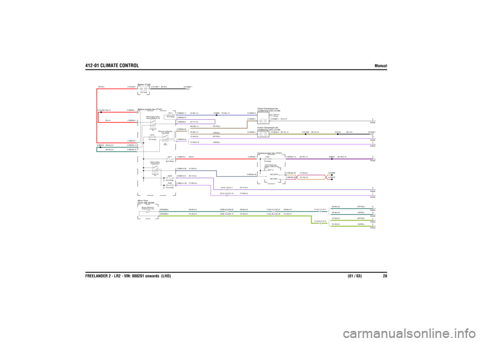
412-01 CLIMATE CONTROL
Manual
FREELANDER 2 - LR2 - VIN: 000201 onwards (LHD) (01 / 03) 28
412-01 CLIMATE CONTROLManual
GN-BU,0.5
RD,25.0
RD,4.0GN-BU,0.5RD,4.0
YE-GN,0.5
YE-GN,0.5 (DIESEL)
VT-WH,0.5 (PETROL)VT-WH,0.75 (DIESEL)
BK-YE,1.5
VT-WH,0.5GY-VT,6.0
GY,0.75
VT-GN,0.5RD,6.0VT-WH,0.5GY-VT,6.0YE-GN,0.5GN-BU,0.5
YE-GN,0.5GN-BU,0.5
GY-BN,1.5
(DIESEL)WH-BN,1.0 (PETROL)GY-BU,1.0GY-VT,4.0
BK,35.0
GY-BU,1.0
BU-RD,0.75
YE-GN,0.5 (PETROL)GN-BU,0.5 (PETROL)GN-BU,0.5 (DIESEL)
GN-BU,0.5
BU-RD,1.0GY-OG,0.5VT-OG,0.5
BK-YE,4.0
BK,10.0
FS27
5.0 AmpsModule (CEM) (D316)
Central Electronics
FE11
10.0 Amps
temperature (T119)
Sensor-Ambient air-
Driver side (M168)
Mirror-Door-Battery (P100)12.0 VoltsBattery junction-box (P147)
C11N-6 C11P-6
K
Sheet2
module (ECM) (R116) Relay-Engine control-POWER MINI
RE2
(A/C) (R180)
Relay-Air conditioning-RE3
MICRO
circuits (R101)
Relay-auxiliary-POWER MINI
RE5
C12G-36 C12H-36C12G-31 C12H-31
conditioning (A/C) (D149)
Clutch-Compressor-Air-
Fixings
Earth via
conditioning (A/C) (D149)
Clutch-Compressor-Air-Central junction-box (P101)
FE39
10.0 AmpsFE28
40.0 AmpsFE17
60.0 Amps
C25B-19 C25A-19C25B-20 C25A-20C21D-7 C21C-7C21D-12 C21C-12
FE13
15.0 Amps
C11N-7 C11P-7
H
Sheet2J
Sheet2G
Sheet2F
Sheet3E
Sheet2D
Sheet2B
Sheet2C
Sheet2A
Sheet2
C1BB03A-31C1BB03A-1
S1DC02AS1BB07A
C1BB03A-10C1BB01B-1C1BB03A-7C1DC02A-1
BATT AC1H302E-2C1H302F-1MS CAN LMS CAN H
C1BB01A-124
C5PM26B-6C5PM26B-5
C1BB01A-51C1BB01A-38C1BB07G-1
C1BP02A-48C1BP02G-1
C1BB03A-29C1BB03A-30C1BB03A-37C1BB03A-8C1BB03A-17
C1D134B-1
G1D108A-1
S1BB38
C1H302E-1C1H302F-2C1H302D-1
C1BP02A-50C1BP02A-49C1BP02C-74
S1DB07FS1DB06FS2BB27
S1D129
S1D129B
G1D129-1
Page 3019 of 3229
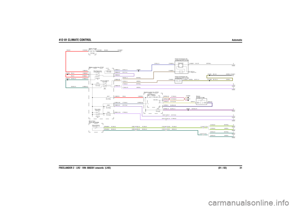
412-01 CLIMATE CONTROL
Automatic
FREELANDER 2 - LR2 - VIN: 000201 onwards (LHD) (01 / 03) 31
Automatic
RD,25.0
GN-BU,0.5RD,4.0RD,4.0GN-BU,0.5
GN-BU,0.5 (DIESEL)
GN-BU,0.5GY-OG,0.5VT-OG,0.5
GY-BU,1.0
VT-WH,0.75 (DIESEL)
GY-VT,6.0VT-WH,0.5YE-GN,0.5
GY-BN,1.5 (DIESEL)WH-BN,1.0 (PETROL)VT-WH,0.5 (PETROL)
BU-RD,1.0BU-BN,0.35GY-YE,0.35
VT-WH,0.5
YE-GN,0.5GN-BU,0.5
GY-VT,6.0VT-GN,0.5RD,6.0
GN-BU,0.5YE-GN,0.5
GY-BU,1.0GY-VT,4.0
BK,35.0
GN-BU,0.5 (PETROL)YE-GN,0.5 (PETROL)YE-GN,0.5 (DIESEL)
BU-RD,0.75
GY,0.75 (PETROL)
BK-YE,4.0 (DIESEL)BK,10.0 (DIESEL)
BK-YE,1.5
(DIESEL)
FS27
5.0 Amps
Module (CEM) (D316)
Central Electronics
FE11
10.0 Amps
temperature (T119)
Sensor-Ambient air-
Driver side (M168)
Mirror-Door-
module (ECM) (R116) Relay-Engine control-POWER MINI
RE2
Battery junction-box (P147)Battery (P100)12.0 Volts
K
Sheet2
(A/C) (R180)
Relay-Air conditioning-RE3
MICRO
circuits (R101)
Relay-auxiliary-POWER MINI
RE5
C25B-19 C25A-19C25B-20 C25A-20
FE39
10.0 AmpsFE28
40.0 AmpsFE17
60.0 Amps
Central junction-box (P101)
C12G-36 C12H-36C12G-31 C12H-31C21D-12 C21C-12C21D-7 C21C-7
FE13
15.0 Amps
C11N-6 C11P-6C11N-7 C11P-7
Sunlight (T166)
Sensor-
H
Sheet2J
Sheet2G
Sheet2F
Sheet3E
Sheet2D
Sheet2
Clutch-Control
conditioning (A/C) (D149)
Clutch-Compressor-Air-
fixings (E110)
Earth via-
conditioning (A/C) (D149)
Clutch-Compressor-Air-
B
Sheet2C
Sheet2A
Sheet2
S1BB07AS1DC02A
C1BB03A-10C1BB03A-31C1BB03A-7C1BB03A-1C1BB01B-1C1DC02A-1
C1H302E-1C1H302F-2C1H302D-1
C1BB01A-124
C5PM26B-5C5PM26B-6
C1BB01A-38C1BB01A-51C1BB07G-1
C1BP02A-48C1BP02G-1
BATT A
C1BP02C-2C1BP02C-74C1BP02C-1
MS CAN HMS CAN L
C1BP02A-50C1BP02A-49
C1BB03A-30C1BB03A-29C1BB03A-37C1BB03A-8C1BB03A-17
C1D134B-1
G1D108A-1
S1BB38
C2H415-5
C2H415-1
S2BB27S1DB06FS1DB07F
C1H302E-2
S1D129BS1D129
C1H302F-1
G1D129-1
Page 3022 of 3229
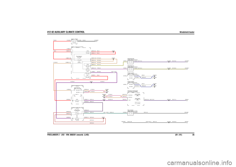
412-02 AUXILIARY CLIMATE CONTROL
Windshield heater
FREELANDER 2 - LR2 - VIN: 000201 onwards (LHD) (01 / 01) 35
412-02 AUXILIARY CLIMATE CONTROLWindshield heater
BU-RD,0.75GN-BU,4.0VT-OG,0.5GY-OG,0.5
VT-BN,4.0YE-GY,4.0
BU-RD,6.0
RD,6.0
GY-OG,0.5
WH-RD,2.5WH-RD,2.5WH-RD,2.5GN-BU,4.0BN-BU,0.5GY-OG,0.5VT-OG,0.5BU-RD,1.0
RD,25.0RD,6.0
GY-OG,6.0GY-OG,6.0
BU-RD,6.0
GY-OG,6.0RD,0.5RD,0.5BU-RD,6.0
BK,35.0
BK-GY,6.0
BK-GY,4.0
BK-VT,1.5
BK-GY,4.00
BK-GY,4.0
BK-VT,0.75
WH,0.5WH-BU,0.5
BK-YE,6.0BK-VT,6.0
BK-YE,4.0BK-VT,4.0
WH,0.5WH-BU,0.5
FS27
5.0 AmpsModule (CEM) (D316)
Central Electronics
Auxiliary junction box (P107)Central junction-box (P101)
rear screen (R138)
Relay-Heated-
RA1
MINIFA7
30.0 Amps
C44L-1 C44K-1
FE33
5.0 AmpsFE17
60.0 AmpsFE19
60.0 AmpsFE34
40.0 AmpsFE35
40.0 Amps
Battery junction-box (P147)Battery (P100)
screen (R208)
Relay-Heated front-RE6
POWER MINI
C12D-1 C12C-1
12.0 Volts
module (ECM) (D131)
Engine control-
(DIESEL)
C44K-2 C44L-2
rear screen (S120) Switch-Heated-
Control Module (D243)
Automatic Temperatureheater element (H100)
Rear window
Defrost
front screen (S261) Switch-Heated-
heater element (H114)
Windshield LHmodule (ECM) (D131)
Engine control-
(PETROL)
heater element (H113)
Windshield RH
S3BB19
C4BR02A-9C1BP02G-1C4BR02A-25C4BR02A-31C1BP02A-5
C4BR02A-15
S4BR07
C1BP02C-74C4BR02A-29C4BR02A-33C1BP02B-26C1BP02A-49C1BP02A-50
MS CAN LBATT AMS CAN H
S2BB27S2DB07GS2DB06G
S1DB07FS1DB06F
C1BB01B-1C1BB01A-108C1BB01A-110C1BB01A-66C1DC02A-1
C1BB07G-1C1BB03J-1C1BB01A-49C1BB01A-109C1BB01A-48C1BB01A-47C1BB01A-46C1BB01A-111C1BB01A-92
S1RD05S1BB33
G1D108A-1
C1D134B-1
G4D149D-1
S4D149B
C2H101D-18
C2H101D-1
BATT
C4RD02C-1
C4RD02A-1
C1E104H-A1
HS CAN LC1E104H-A2
HS CAN H
C2H101D-11 MS CAN LC2H101D-10MS CAN H
S2D134A
S1DB05FS1DB04F
G4D149-1G3D134-1G4D149E-1
C1E109B-41
HS CAN LC1E109B-54
HS CAN HC1RD03-2
C1RD03-1
C1RD04-2
C1RD04-1
S1DB05GS1DB04G
S1D130BS1D132B
G1D130A-1G1D132A-1