Page 1895 of 3383
. Then make sure that there are no lea")
EM-4Revision: November 2009
PRECAUTIONS
2006 QX56
�Before starting engine, apply fuel pressure to fuel lines with turning ignition switch ON (with engine
stopped). Then make sure that there are no leaks at fuel line connections.
�After repairing, start engine and increase engine speed to check engine coolant, fuel, oil, and exhaust
systems for leakage.
Parts Requiring Angular TighteningEBS00REO
�For final tightening of the following engine parts use Tool:
–Cylinder head bolts
–Main bearing cap bolts
–Connecting rod cap bolts
–Crankshaft pulley bolt (No angle wrench is required as the bolt flange is provided with notches for angle
tightening)
�Do not use a torque value for final tightening.
�The torque value for these parts are for a preliminary step.
�Ensure thread and seat surfaces are clean and lightly coated with engine oil.
Precautions for Liquid GasketEBS00REP
REMOVAL OF LIQUID GASKET SEALING
�After removing the bolts and nuts, separate the mating surface
and remove the old liquid gasket sealing using Tool.
CAUTION:
Do not damage the mating surfaces.
�Tap the seal cutter to insert it.
�In areas where the Tool is difficult to use, lightly tap to slide it.
LIQUID GASKET APPLICATION PROCEDURE
1. Remove the old liquid gasket adhering to the gasket applicationsurface and the mating surface using suitable tool.
�Remove the liquid gasket completely from the groove of the
liquid gasket application surface, bolts, and bolt holes.
2. Thoroughly clean the mating surfaces and remove adhering moisture, grease and foreign material.
3. Attach the liquid gasket tube to the Tool. Use Genuine RTV Silicone Sealant or equivalent. Refer to
GI-46, "
Recommended Chemical Products and Sealants" .
4. Apply the liquid gasket without breaks to the specified location with the specified dimensions.Tool number : KV10112100 (BT-8653-A)
Tool number : KV10111100 (J-37228)
WBIA0566E
PBIC0003E
Tool number : WS39930000 ( — )
WBIA0567E
Page 1896 of 3383
PRECAUTIONSEM-5
C
DE
F
G H
I
J
K L
M A
EM
Revision: November 2009 2006 QX56
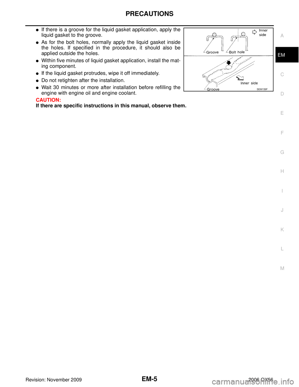
�If there is a groove for the liquid gasket application, apply the
liquid gasket to the groove.
�As for the bolt holes, normally apply the liquid gasket inside
the holes. If specified in the procedure, it should also be
applied outside the holes.
�Within five minutes of liquid gasket application, install the mat-
ing component.
�If the liquid gasket protrudes, wipe it off immediately.
�Do not retighten after the installation.
�Wait 30 minutes or more after installation before refilling the
engine with engine oil and engine coolant.
CAUTION:
If there are specific instructions in this manual, observe them.SEM159F
Page 1902 of 3383
 TROUBLESHOOTINGEM-11
C
DE
F
G H
I
J
K L
M A
EM
Revision: November 2009 2006 QX56
Use the Chart Below to Help You Find the Cause of the Symptom.EBS00RET
1. Locate")
NOISE, VIBRATION, AND HARSHNESS (NVH) TROUBLESHOOTINGEM-11
C
DE
F
G H
I
J
K L
M A
EM
Revision: November 2009 2006 QX56
Use the Chart Below to Help You Find the Cause of the Symptom.EBS00RET
1. Locate the area where noise occurs.
2. Confirm the type of noise.
3. Specify the operating condition of engine.
4. Check specified noise source.
If necessary, repair or replace these parts.
A: Closely related B: Related C: Sometimes related—: Not related
Location of
noise Type of
noise Operating condition of engine
Source of noise Check item Refer-
ence page
Before
warm- up After
warm- up When
start- ing When
idling When
racing While
driv- ing
Top of
engine
Rocker
cover
Cylinder
head Ticking or
clicking
CA
—AB —Tappet noise Valve clearance EM-69
Rattle C A—ABC Camshaft
bearing noiseCamshaft journal clear-
ance
Camshaft runout EM-50EM-50
Crankshaft
pulley
Cylinder
block (Side
of engine)
Oil panSlap or
knock
—
A— BB —Piston pin
noise Piston and piston pin
clearance
Connecting rod bush-
ing clearance EM-95
EM-97
Slap or
rap
A
—— BBA Piston slap
noisePiston-to-bore clear-
ance
Piston ring side clear-
ance
Piston ring end gap
Connecting rod bend
and torsion EM-99EM-95
EM-95
EM-96
Knock A B C B B B
Connecting
rod bearing
noiseConnecting rod bush-
ing oil clearance (Small
end)
Connecting rod bear-
ing clearance (Big end)
EM-97EM-96
Knock A B
—ABC Main bearing
noiseMain bearing oil clear-
ance
Crankshaft runout EM-101EM-100
Front of
engine
Chain case
cover
Front coverTapping
or ticking
AA
—BBB Timing chain
and chain
tensioner
noiseTiming chain cracks
and wear
Timing chain tensioner
operation
EM-40
EM-37
Front of
engineSqueak-
ing or
fizzing
AB
—B— CDrive belts
(Sticking or
slipping) Drive belts deflection
EM-13
Creaking A B A B A B Drive belts
(Slipping)Idler pulley bearing
operation
Squall
Creaking AB
—BAB Water pump
noiseWater pump operation CO-19,
"INSPEC-
TION
AFTER
REMOVA
L"
Page 1910 of 3383

INTAKE MANIFOLDEM-19
C
DE
F
G H
I
J
K L
M A
EM
Revision: November 2009 2006 QX56
INSTALLATION
Installation is in the reverse order of removal.
�Tighten the intake manifold bolts in numerical order as shown.
�Install the EVAP canister purge control solenoid valve connector with it facing front of engine.
�Tighten the electronic throttle control actuator bolts of the electric throttle control actuator equally and
diagonally in several steps.
�After installation perform procedure in EM-20, "INSPECTION AFTER INSTALLATION" .
�Install the water hose so that its overlap width for connection is between 27 mm (1.06 in) and 32 mm (1.26
in) (target: 27 mm 1.06 in).
Connecting Quick Connector of Fuel Tube
Install quick connector as follows (the steps are the same for quick connectors on both engine side and vehi-
cle side except for the quick connector cap).
1. Make sure no foreign substances are deposited in and around tube and quick connector, and they are not
damaged.
2. Thinly apply new engine oil around the fuel tube from tip end to the spool end.
3. Align center to insert quick connector straight into fuel tube.
�Insert until the paint mark for engagement identification
(white) goes completely inside quick connector so that you
cannot see it from the straight side of the connected part. Use
a mirror to check this where it is not possible to view directly
from the straight side, such as quick connector on vehicle
side.
�Insert fuel tube into quick connector until top spool is com-
pletely inside quick connector, and 2nd level spool exposes
right below quick connector on engine side.
CAUTION:
�Hold "A" position in illustration when inserting fuel
tube into quick connector.
�Carefully align center to avoid inclined insertion to pre-
vent damage to O-ring inside quick connector.
�Insert until you hear a "click" sound and actually feel
the engagement.
�To avoid misidentification of engagement with a similar
sound, be sure to perform the next step.
4. Pull quick connector by hand holding "A" position. Make sure it is completely engaged (connected) so that it does not come out from fuel tube.
NOTE:
Recommended pulling force is 50 N (5.1 kg, 11.2 lb).
KBIA2462E
PBIC0017E
KBIA0272E
Page 1913 of 3383

EM-22Revision: November 2009
EXHAUST MANIFOLD AND THREE WAY CATALYST
2006 QX56
b. Remove the air fuel ratio A/F sensors from both left and rightexhaust manifolds using Tool.
CAUTION:
�Do not damage the air fuel ratio A/F sensors
�Discard any air fuel ratio A/F sensor which has been
dropped from a height of more than 0.5m (19.7 in) onto a
hard surface such as a concrete floor. Replace it with a
new one.
8. Support engine using a suitable tool.
9. Remove the exhaust manifold (LH) following the steps below.
a. Remove the engine mounting insulator. Refer to EM-74
.
b. Remove the exhaust manifold cover.
c. Remove the engine mounting bracket. Refer to EM-74
.
d. Loosen the nuts in reverse order as shown using power tool.
e. Remove the exhaust manifold (LH) (A).
10. Remove the exhaust manifold (RH) following the steps below.
a. Remove the engine mounting insulator. Refer to EM-74
.
b. Remove the exhaust manifold cover.
c. Remove the engine mounting bracket. Refer to EM-74
.
d. Remove the oil level gauge guide. Refer to EM-24
.
e. Loosen the nuts in reverse order as shown using power tool.
f. Remove the exhaust manifold (RH) (B).
INSPECTION AFTER REMOVAL
Surface Distortion
�Check the flatness of each exhaust manifold flange surface
using suitable tools.
�If measurement exceeds the limit, replace the exhaust manifold.
INSTALLATION
Installation is in the reverse order of removal. Tool number : — (J-44626)
WBIA0630E
WBIA0696E
WBIA0696E
Flatness limit : 0.3 mm (0.012 in)
KBIA2504E
Page 1915 of 3383
EM-24Revision: November 2009
OIL PAN AND OIL STRAINER
2006 QX56
OIL PAN AND OIL STRAINERP F P : 1111 0
Removal and InstallationEBS00RF2
REMOVAL
WARNING:
To avoid the danger of being scalded, never drain the engine oil when the engine is hot.
1. Remove the engine. Refer to EM-74, "
REMOVAL" .
2. Remove the oil pan (lower) using the following steps.
a. Remove the oil pan (lower) bolts using power tool.
1. Oil pan (upper) 2. O-ring3. O-ring
4. O-ring 5. O-ring (with collar)6. Oil level gauge guide
7. Oil level gauge 8. O-ring9. Connector bolt
10. Oil filter 11. Oil cooler12. Relief valve
13. Oil pressure sensor 14. Gasket15. Drain plug
16. Oil pan (lower) 17. Oil strainer
KBIA2465E
KBIA2466E
Page 1918 of 3383
OIL PAN AND OIL STRAINEREM-27
C
DE
F
G H
I
J
K L
M A
EM
Revision: November 2009 2006 QX56
b. Tighten the oil pan (lower) bolts in numerical order as shown.
4. Install the oil pan drain plug.
5. Install engine assembly. Refer to EM-76, "
INSTALLATION" .
�Do not fill the engine oil for at least 30 minutes after oil pan is installed.
INSPECTION AFTER INSTALLATION
1. Check engine oil level and add engine oil if necessary. Refer to LU-7, "OIL LEVEL" .
2. Start the engine, and check for leaks of engine oil.
3. Stop engine and wait for 10 minutes.
4. Check engine oil level again.
PBIC2595E
Page 1919 of 3383
EM-28Revision: November 2009
IGNITION COIL
2006 QX56
IGNITION COILPFP:22448
Removal and InstallationEBS00RF3
REMOVAL
1. Remove the engine room cover using power tool. Refer to EM-12, "REMOVAL" .
2. Disconnect the harness connector from the ignition coil.
3. Remove the ignition coil. CAUTION:
Do not shock ignition coil.
INSTALLATION
Installation is in the reverse order of removal.
1. Ignition coil 2. Spark plug
KBIA2505E

 bolts in numerical order as shown.
4. Install the oil pan drain plug.
5. Instal")
