Page 1923 of 3383

EM-32Revision: November 2009
FUEL INJECTOR AND FUEL TUBE
2006 QX56
7. Remove the fuel injector from the fuel tube using the followingsteps.
a. Spread open and remove the clip.
b. Remove the fuel injector from the fuel tube by pulling straight out.
CAUTION:
�Be careful with remaining fuel that may leak out from fuel
tube.
�Do not damage injector nozzles during removal.
�Do not bump or drop fuel injectors.
�Do not disassemble fuel injectors.
8. Remove the fuel damper from each fuel tube.
INSTALLATION
1. Install the fuel damper to each fuel tube using the following steps.
a. Apply engine oil to the new O-ring and set it into the cup of the fuel tube.
CAUTION:
�Handle O-ring with bare hands. Never wear gloves.
�Lubricate new O-ring with new engine oil.
�Do not clean O-ring with solvent.
�Make sure that O-ring and its mating part are free of for-
eign material.
�When installing O-ring, do not scratch it with tool or fin-
gernails.
�Do not twist or stretch the O-ring.
b. Make sure that the backup spacer is in the O-ring connecting surface of the fuel damper. NOTE:
The backup spacer is part of the fuel damper assembly.
c. Insert the fuel damper until it seats on the fuel tube. CAUTION:
�Insert straight, making sure that the axis is lined up.
�Do not pressure-fit with excessive force.
d. Install the cap, and then tighten the bolts evenly.
�After tightening the bolts, make sure that there is no gap between the cap and fuel tube.
2. Install new O-rings to the fuel injector paying attention to the items below. CAUTION:
�Upper and lower O-rings are different colors.
KBIA2506E
Reference value :130 N (13.3 kg, 29.2 lb)
Fuel tube side : Blue
Nozzle side : Brown
KBIA2473E
Page 1924 of 3383

FUEL INJECTOR AND FUEL TUBEEM-33
C
DE
F
G H
I
J
K L
M A
EM
Revision: November 2009 2006 QX56
�Handle O-ring with bare hands. Never wear gloves.
�Lubricate new O-ring with new engine oil.
�Do not clean O-ring with solvent.
�Make sure that O-ring and its mating part are free of foreign material.
�When installing O-ring, be careful not to scratch it with tool or fingernails. Also be careful not to
twist or stretch O-ring.
�If O-ring was stretched while it was being attached, do not insert it quickly into fuel tube.
�Insert O-ring straight into fuel tube. Do not angle or twist it.
3. Install the fuel injector to the fuel tube using the following steps.
a. Insert new clip into clip mounting groove on the fuel injector.
�Insert clip so that lug ″A″ of fuel injector matches notch ″A″ of
the clip.
CAUTION:
�Do not reuse clip. Replace it with a new one.
�Do not allow the clip to interfere with the O-ring. If
interference occurs, replace the O-ring.
b. Insert the fuel injector into the fuel tube with the clip attached.
�Insert it while matching it to the axial center.
�Insert fuel injector so that lug ″B″ of fuel tube matches notch
″ B″ of the clip.
�Make sure that the fuel tube flange is securely seated in the
flange fixing groove on the clip.
c. Make sure that installation is complete by checking that the fuel injector does not rotate or come off.
�Make sure that the protrusions of the fuel injectors are aligned
with the cutouts of the clips after installation.
4. Install the fuel tube and fuel injector assembly to the intake manifold. CAUTION:
Do not let the tip of the injector nozzle come in contact with other parts.
�Tighten fuel tube assembly bolts ″a ″ to ″b ″ in illustration in two
steps.
5. Install the fuel hose assembly.
�Insert connectors straight, making sure that the axis is lined up with fuel tube side to prevent O-ring
from being damaged.
�Tighten bolts evenly in several steps.
�Make sure that there is no gap between the flange and fuel tube after tightening the bolts.
CAUTION:
�Handle O-ring with bare hands. Do not wear gloves.
�Lubricate O-ring with new engine oil.
�Do not clean O-ring with solvent.
KBIA2507E
1st step : 12.8 N·m (1.3 kg-m, 9 ft-lb)
2nd step : 24.5 N·m (2.5 kg-m, 18 ft-lb)
KBIA2474E
Page 1926 of 3383
ROCKER COVEREM-35
C
DE
F
G H
I
J
K L
M A
EM
Revision: November 2009 2006 QX56
ROCKER COVERPFP:13264
Removal and InstallationEBS00RF6
REMOVAL
1. Remove the engine room cover using power tool. Refer to EM-12, "REMOVAL" .
2. Remove the air duct and resonator assembly. Refer to EM-15, "
REMOVAL" (for LH only).
3. Move the harness on the upper rocker cover and its peripheral aside.
4. Remove the electric throttle control actuator, loosening the bolts diagonally (for LH only).
5. Remove the ignition coils. Refer to EM-28, "
REMOVAL" .
6. Remove the PCV hose from the PCV control valves.
�⇐ : Engine front
7. Loosen the bolts in reverse order shown using power tool for rocker cover (A) or (B).
CAUTION:
Do not hold the rocker cover (RH) (B) by the oil filler neck.
1. Rocker cover (LH) 2. PCV control valve3. O-ring
4. Rocker cover gasket (LH) 5. Rocker cover (RH)6. PCV control valve
7. O-ring 8. Oil filler cap9. Rocker cover gasket (RH)
KBIA2508E
WBIA0697E
Page 1929 of 3383

EM-38Revision: November 2009
TIMING CHAIN
2006 QX56
NOTE:
�To remove timing chain and associated parts, start with those on the LH bank. The procedure for remov-
ing parts on the RH bank is omitted because it is the same as that for removal on the LH bank.
�To install timing chain and associated parts, start with those on the RH bank. The procedure for installing
parts on the LH bank is omitted because it is the same as that for installation on the RH bank.
REMOVAL
1. Remove the engine assembly from the vehicle. Refer to EM-74, "REMOVAL" .
2. Remove the following components and related parts:
�Drive belt auto tensioner and idler pulley. Refer to EM-13, "REMOVAL" .
�Thermostat housing and water hose. Refer toCO-21, "Removal of Thermostat Housing, Water Outlet
and Heater Pipe" .
�Power steering oil pump bracket. Refer to PS-21, "REMOVAL" .
�Oil pan (lower), (upper) and oil strainer. Refer to EM-24, "REMOVAL" .
�Ignition coil. Refer to EM-28, "REMOVAL" .
�Rocker cover. Refer to EM-35, "REMOVAL" .
3. Remove the chain case cover RH bank (A) and chain case cover LH bank (B) as follows:
a. Loosen and remove the bolts as shown.
b. Cut the liquid gasket and remove the covers using Tool.
CAUTION:
Do not damage mating surfaces.
4. Obtain compression TDC of No. 1 cylinder as follows:
a. Turn the crankshaft pulley clockwise to align the TDC identifica- tion notch (without paint mark) with the timing indicator on the
front cover.
1. Camshaft sprocket LH bank EXH 2. Camshaft sprocket LH bank INT 3. Camshaft sprocket RH bank INT
4. Camshaft sprocket RH bank EXH 5. Front cover 6. Chain case cover RH bank
7. Chain case cover LH bank 8. Crankshaft pulley bolt 9. Crankshaft pulley
10. Chain tensioner cover 11. Front oil seal 12. Oil pump drive spacer
13. Oil pump assembly 14. Crankshaft sprocket 15. Bracket
16. O-ring 17. Timing chain tension guide RH bank 18. Timing chain slack guide RH bank
19. Timing chain RH bank 20. Timing chain LH bank 21. Chain tensioner RH bank
22. Timing chain slack guide LH bank 23. Timing chain tension guide LH bank 24. Chain tensioner LH bank
Tool number : KV10111100 (J-37228)
WBIA0698E
KBIA2476E
Page 1934 of 3383
TIMING CHAINEM-43
C
DE
F
G H
I
J
K L
M A
EM
Revision: November 2009 2006 QX56
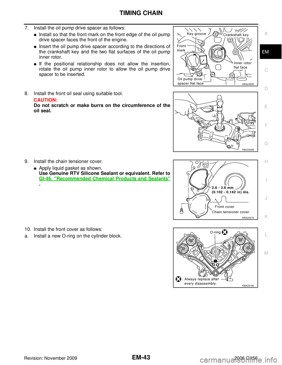
7. Install the oil pump drive spacer as follows:
�Install so that the front mark on the front edge of the oil pump
drive spacer faces the front of the engine.
�Insert the oil pump drive spacer according to the directions of
the crankshaft key and the two flat surfaces of the oil pump
inner rotor.
�If the positional relationship does not allow the insertion,
rotate the oil pump inner rotor to allow the oil pump drive
spacer to be inserted.
8. Install the front oil seal using suitable tool. CAUTION:
Do not scratch or make burrs on the circumference of the
oil seal.
9. Install the chain tensioner cover.
�Apply liquid gasket as shown.
Use Genuine RTV Silicone Sealant or equivalent. Refer to
GI-46, "
Recommended Chemical Products and Sealants"
.
10. Install the front cover as follows:
a. Install a new O-ring on the cylinder block.
KBIA2490E
PBIC0059E
KBIA2547E
KBIA2516E
Page 1936 of 3383
TIMING CHAINEM-45
C
DE
F
G H
I
J
K L
M A
EM
Revision: November 2009 2006 QX56
a. Apply engine oil onto the threaded parts of the bolt and seating area.
b. Select the one most visible notch of the four on the bolt flange.
Corresponding to the selected notch, put a alignment mark
(such as paint) on the crankshaft pulley.
14. Rotate the crankshaft pulley in normal direction (clockwise when viewed from engine front) to check for parts interference.
15. Installation of the remaining components is in the reverse of order of removal.Crankshaft pulley bolt torque
Step 1 : 93.1 N·m (9.5 kg-m, 69 ft-lb)
Step 2 : additional 90
° (angle tightening)
KBIA2519E
Page 1951 of 3383

EM-60Revision: November 2009
OIL SEAL
2006 QX56
OIL SEALPFP:00100
Removal and Installation of Valve Oil SealEBS00RFA
REMOVAL
1. Remove the camshaft relating to the valve oil seal to be removed. Refer to EM-46, "Removal and Installa-
tion" .
2. Remove the valve lifters. Refer to EM-46, "
Removal and Installation" .
�Correctly identify the location where each part is removed from. Keep parts organized to avoid mixing
them up.
3. Turn the crankshaft until the cylinder requiring new oil seals is at TDC. This will prevent the valve from dropping into the cylinder.
4. Remove the valve collet using Tool.
CAUTION:
Do not damage the valve lifter holes.
5. Remove the valve spring retainer and valve spring. CAUTION:
Do not remove the valve spring seat from the valve spring.
6. Remove the valve oil seal using Tool.
INSTALLATION
Installation is in the reverse order of removal.
�Install the valve oil seal using Tool.
�Apply new engine oil on the new valve oil seal joint and seal lip.
�Install the valve oil seal to the specified height "H". Tool number
: KV10116200 (J-26336-A)
: KV10115900 (J-26336-20)
: KV10109220 ( — )
WBIA0578E
Tool number : KV10107902 (J-38959)
WBIA0478E
Tool number : KV10115600 (J-38958)
Height "H" (without valve spring installed) Intake and exhaust : 14.3 - 14.9 mm (0.563 - 0.587 in)
WBIA0490E
Page 1952 of 3383

OIL SEALEM-61
C
DE
F
G H
I
J
K L
M A
EM
Revision: November 2009 2006 QX56
Removal and Installation of Front Oil SealEBS00RFB
REMOVAL
1. Remove the engine. Refer to EM-74, "Removal and Installation" .
2. Remove the crankshaft pulley. Refer to EM-37, "
TIMING CHAIN" .
3. Remove the front oil seal using suitable tool. CAUTION:
Do not damage front cover and oil pump drive spacer.
INSTALLATION
1. Apply new engine oil to both the oil seal lip and dust seal lip of the new front oil seal.
2. Install the front oil seal.
�Install the front oil seal so that each seal lip is oriented as
shown.
�Press-fit until the height of the front oil seal is level with the
mounting surface using suitable tool.
CAUTION:
�Do not damage front timing chain case and crankshaft.
�Press-fit straight and avoid causing burrs or tilting oil
seal.
3. Installation of the remaining components is in the reverse order of removal.
Removal and Installation of Rear Oil SealEBS00RFC
REMOVAL
1. Remove the transmission assembly. Refer to AT- 2 4 3 , "Removal and Installation (2WD)" or AT- 2 4 6 ,
"Removal and Installation (4WD)" .
SBIA0359E
SEM715A
PBIC2931E