Page 2964 of 5267
48. Install #1 caged needle bearing (1).
CAUTION: By-pass valve MUST be replaced if a
transmission failure has occured.
49. Replace cooler by-pass valve (1) if transmission
failure has occurred.
NOTE: To align oil pump, gasket, and case during
installation, use threadeddowels or phillips screw-
drivers.
50. Install oil pump gasket (2).
Page 2965 of 5267
51. Install oil pump (2) and torque oil pump-to-case
bolts (1) to 30 Nꞏm (265 in. lbs.). Do not reuse
original oil pump bolts.
52. Install low/reverse accumulator (1) as shown.
53. Install low/reverse accumulator plug (2).
Page 2967 of 5267
57. Install seven (7) valve body-to-case bolts (1) and
torque to 12 Nꞏm (105 in. lbs.).
58. Install transmission oil filter (1). Tighten the bolts
to5Nꞏm(45in.lbs.).
59. Install transmission oil pan (1) with a bead of
Mopar
AT F R T V.
Page 2968 of 5267

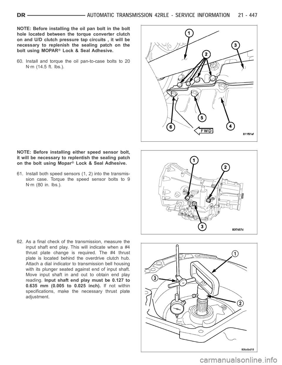
NOTE: Before installing the oil pan bolt in the bolt
hole located between the torque converter clutch
on and U/D clutch pressure tap circuits , it will be
necessary to replenish the sealing patch on the
bolt using MOPAR
Lock & Seal Adhesive.
60. Install and torque the oil pan-to-case bolts to 20
Nꞏm (14.5 ft. lbs.).
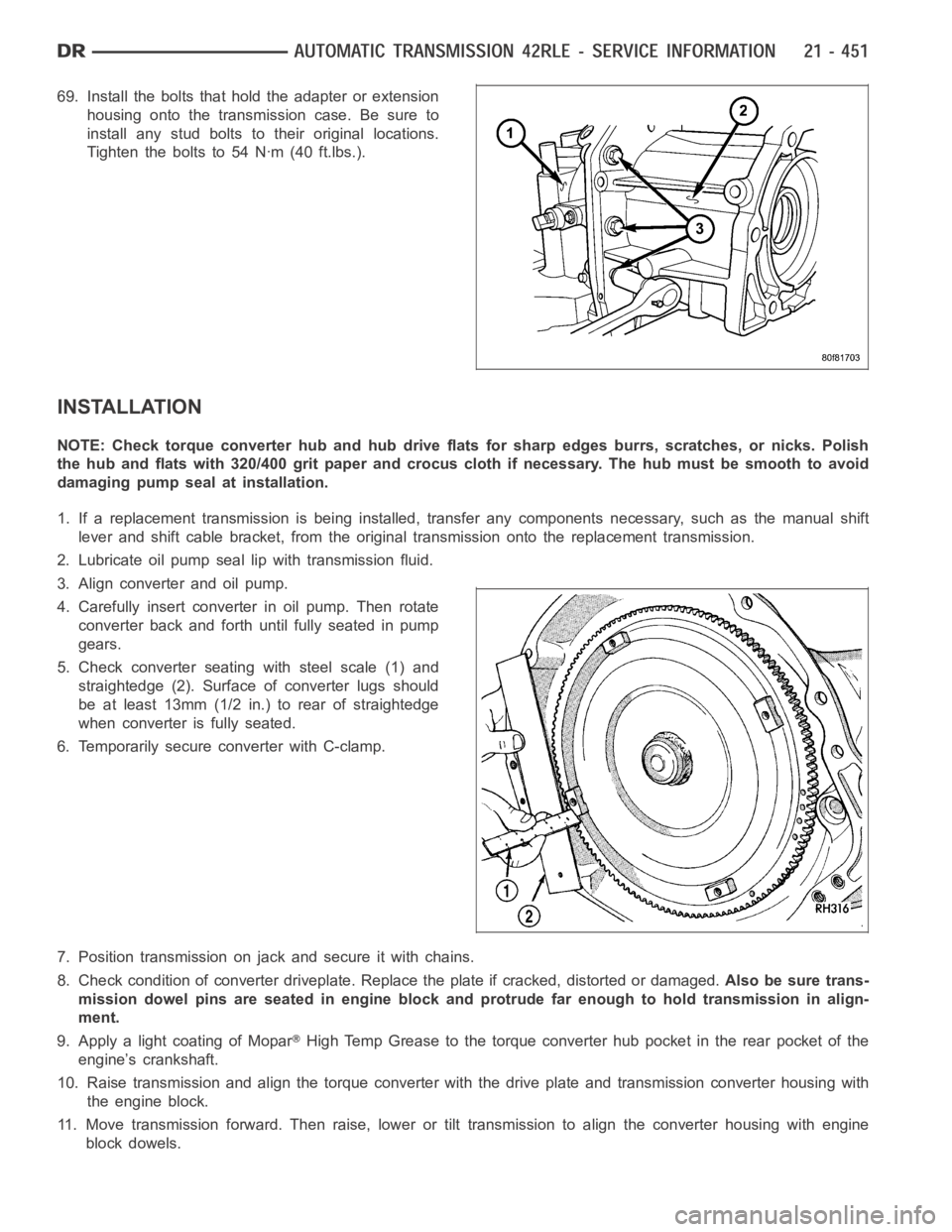
NOTE: Before installing either speed sensor bolt,
it will be necessary to replentish the sealing patch
on the bolt using Mopar
Lock & Seal Adhesive.
61. Install both speed sensors (1, 2) into the transmis-
sion case. Torque the speed sensor bolts to 9
Nꞏm (80 in. lbs.).
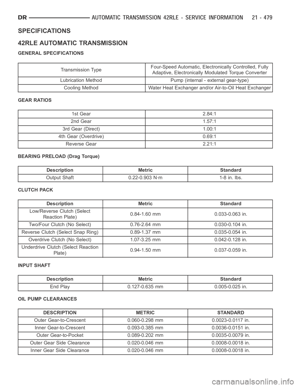
62. As a final check of the transmission, measure the
input shaft end play. This will indicate when a #4
thrust plate change is required. The #4 thrust
plate is located behind the overdrive clutch hub.
Attach a dial indicator to transmission bell housing
with its plunger seated against end of input shaft.
Move input shaft in and out to obtain end play
reading.Input shaft end play must be 0.127 to
0.635 mm (0.005 to 0.025 inch).If not within
specifications, make the necessary thrust plate
adjustment.
Page 2972 of 5267

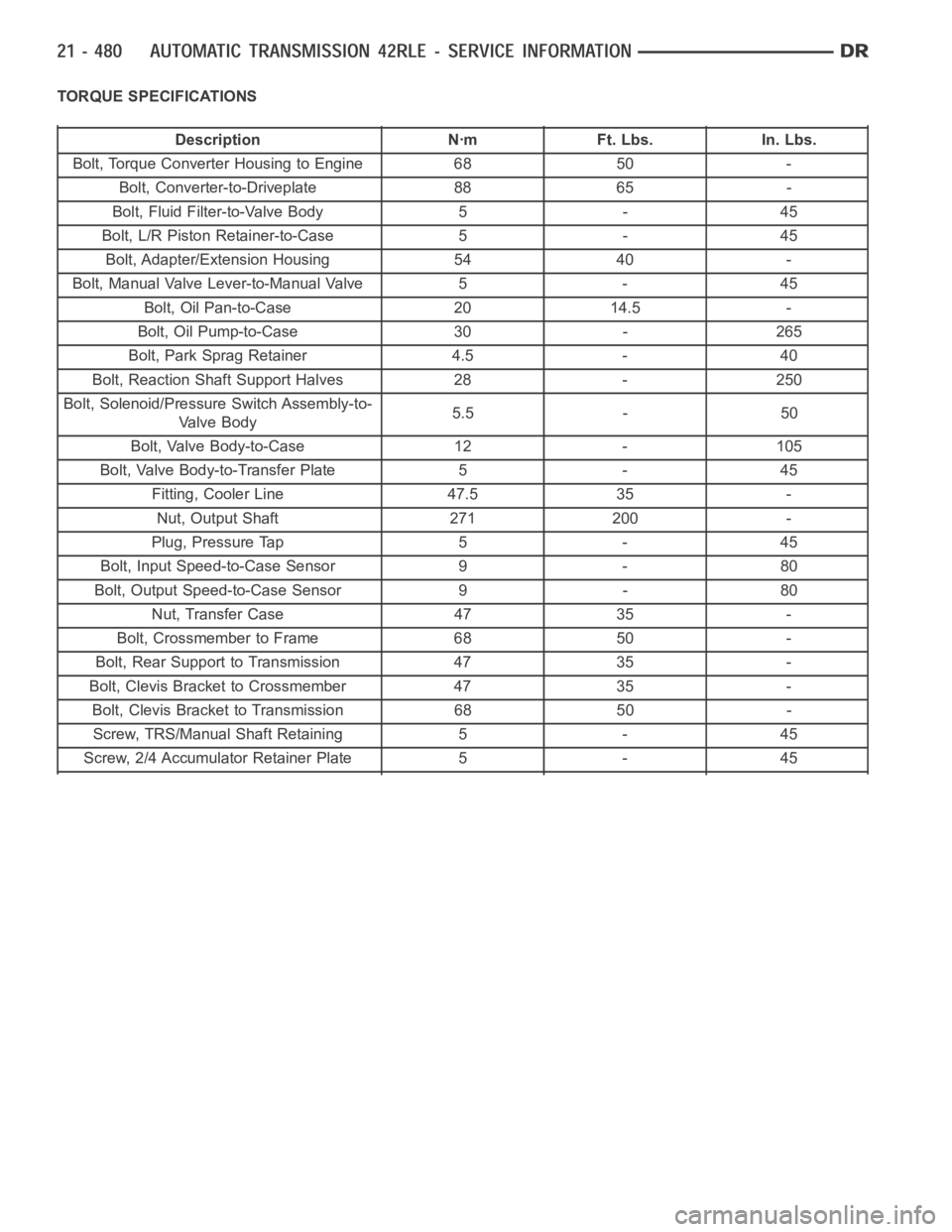
69. Install the bolts that hold the adapter or extension
housing onto the transmission case. Be sure to
install any stud bolts to their original locations.
Tighten the bolts to 54 Nꞏm (40 ft.lbs.).
INSTALLATION
NOTE: Check torque converter hub and hub drive flats for sharp edges burrs,scratches, or nicks. Polish
the hub and flats with 320/400 grit paper and crocus cloth if necessary. Thehub must be smooth to avoid
damaging pump seal at installation.
1. If a replacement transmission is being installed, transfer any components necessary, such as the manual shift
lever and shift cable bracket, from the original transmission onto the replacement transmission.
2. Lubricate oil pump seal lip with transmission fluid.
3. Align converter and oil pump.
4. Carefully insert converter in oil pump. Then rotate
converter back and forth until fully seated in pump
gears.
5. Check converter seating with steel scale (1) and
straightedge (2). Surface of converter lugs should
be at least 13mm (1/2 in.) to rear of straightedge
when converter is fully seated.
6. Temporarily secure converter with C-clamp.
7. Position transmission on jack and secure it with chains.
8. Check condition of converter driveplate. Replace the plate if cracked,distorted or damaged.Also be sure trans-
mission dowel pins are seated in engine block and protrude far enough to holdtransmissioninalign-
ment.
9. Apply a light coating of Mopar
High Temp Grease to the torque converter hub pocket in the rear pocket of the
engine’s crankshaft.
10. Raise transmission and align the torque converter with the drive plateand transmission converter housing with
the engine block.
11. Move transmission forward. Then raise, lower or tilt transmission to align the converter housing with engine
block dowels.
Page 3000 of 5267

SPECIFICATIONS
42RLE AUTOMATIC TRANSMISSION
GENERAL SPECIFICATIONS
Transmission TypeFour-Speed Automatic, Electronically Controlled, Fully
Adaptive, Electronically Modulated Torque Converter
Lubrication Method Pump (internal - external gear-type)
Cooling Method Water Heat Exchanger and/or Air-to-Oil Heat Exchanger
GEAR RATIOS
1st Gear 2.84:1
2nd Gear 1.57:1
3rd Gear (Direct) 1.00:1
4th Gear (Overdrive) 0.69:1
Reverse Gear 2.21:1
BEARING PRELOAD (Drag Torque)
Description Metric Standard
Output Shaft 0.22-0.903 Nꞏm 1-8 in. lbs.
CLUTCH PACK
Description Metric Standard
Low/Reverse Clutch (Select
Reaction Plate)0.84-1.60 mm 0.033-0.063 in.
Two/Four Clutch (No Select) 0.76-2.64 mm 0.030-0.104 in.
Reverse Clutch (Select Snap Ring) 0.89-1.37 mm 0.035-0.054 in.
Overdrive Clutch (No Select) 1.07-3.25 mm 0.042-0.128 in.
Underdrive Clutch (Select Reaction
Plate)0.94-1.50 mm 0.037-0.059 in.
INPUT SHAFT
Description Metric Standard
End Play 0.127-0.635 mm 0.005-0.025 in.
OIL PUMP CLEARANCES
DESCRIPTION METRIC STANDARD
Outer Gear-to-Crescent 0.060-0.298 mm 0.0023-0.0117 in.
Inner Gear-to-Crescent 0.093-0.385 mm 0.0036-0.0151 in.
Outer Gear-to-Pocket 0.089-0.202 mm 0.0035-0.0079 in.
Outer Gear Side Clearance 0.020-0.046 mm 0.0008-0.0018 in.
Inner Gear Side Clearance 0.020-0.046 mm 0.0008-0.0018 in.
Page 3001 of 5267

TORQUE SPECIFICATIONS
Description Nꞏm Ft. Lbs. In. Lbs.
Bolt, Torque Converter Housing to Engine 68 50 -
Bolt, Converter-to-Driveplate 88 65 -
Bolt, Fluid Filter-to-Valve Body 5 - 45
Bolt, L/R Piston Retainer-to-Case 5 - 45
Bolt, Adapter/Extension Housing 54 40 -
Bolt, Manual Valve Lever-to-Manual Valve 5 - 45
Bolt, Oil Pan-to-Case 20 14.5 -
Bolt, Oil Pump-to-Case 30 - 265
Bolt, Park Sprag Retainer 4.5 - 40
Bolt, Reaction Shaft Support Halves 28 - 250
Bolt, Solenoid/Pressure Switch Assembly-to-
Valve Body5.5 - 50
Bolt, Valve Body-to-Case 12 - 105
Bolt, Valve Body-to-Transfer Plate 5 - 45
Fitting, Cooler Line 47.5 35 -
Nut, Output Shaft 271 200 -
Plug, Pressure Tap 5 - 45
Bolt, Input Speed-to-Case Sensor 9 - 80
Bolt, Output Speed-to-Case Sensor 9 - 80
Nut, Transfer Case 47 35 -
Bolt, Crossmember to Frame 68 50 -
Bolt, Rear Support to Transmission 47 35 -
Bolt, Clevis Bracket to Crossmember 47 35 -
Bolt, Clevis Bracket to Transmission 68 50 -
Screw, TRS/Manual Shaft Retaining 5 - 45
Screw, 2/4 Accumulator Retainer Plate 5 - 45
Page 3009 of 5267
BEARINGS
ADJUSTMENTS
BEARING ADJUSTMENT PROCEDURES
Take extreme care when removing andinstalling bearing cups and cones.Use only an arbor press for installa-
tion,as a hammer may not properly align the bearing cup or cone. Burrs or nicks on the bearing seat will give a
false end play reading, while gauging for proper shims. Improperly seatedbearing cup and cones are subject to
low-mileage failure.
Bearing cups and cones should be replaced if they show signs of pitting or heat distress.
If distress is seen on either the cup or bearing rollers, both cup and cone must be replaced.
NOTE: Bearing drag torque specifications must be maintained to avoid premature bearing failures.
Used (original) bearing may lose up to 50 percent of the original drag torque after break-in.
NOTE: All bearing adjustments must be made with no other component interference or gear inter-mesh.
Oil all bearings before checking turning torque.