2006 DODGE RAM SRT-10 battery
[x] Cancel search: batteryPage 213 of 5267

3.TP SENSOR NO.1 AND TP SENSOR NO.2 BOTH EQUAL 2.5 VOLTS
With a scan tool, perform the Throttle Follower test while reading both TP Sensor voltage readings.
Are both TP Sensor readings stuck at 2.5 volts?
Ye s>>
Check the TP Sensor Signal circuits for excessive resistance, being shorted to each other, or shorted to
the Sensor Return circuit.
Perform the POWERTRAIN VERIFICATION TEST. (Refer to 9 - ENGINE - STANDARD PROCEDURE)
No>>
Go To 4
4.(K447) ETC POSITIVE CIRCUIT SHORTED TO BATTERY VOLTAGE
Turn the ignition off.
Disconnect the Throttle Body harness connector.
Disconnect the C2 PCM harness connector.
CAUTION: Do not probe the PCM harness connectors. Probing the
PCM harness connectors will damage the PCM terminals resulting
in poor terminal to pin connection. Install Miller Special Tool #8815
to perform the diagnostics.
Ignition on, engine not running.
With a 12-volt test light connected to ground, probe the (K447) ETC
Positive circuit at the appropriate terminal of special tool #8815.
Does the test light illuminate brightly?
Ye s>>
Repair the short to battery voltage on the (K447) ETC Pos-
itive circuit.
Perform the POWERTRAIN VERIFICATION TEST. (Refer to
9 - ENGINE - STANDARD PROCEDURE)
No>>
Go To 5
5.(K447) ETC POSITIVE CIRCUIT OPEN
Turn the ignition off.
Measure the resistance of the (K447) ETC Positive circuit from the
Throttle Body harness connector to the appropriate terminal of special
tool #8815.
Is the resistance below 5.0 ohms?
Ye s>>
Go To 6
No>>
Repair the open in the (K447) ETC Positive circuit.
Perform the POWERTRAIN VERIFICATION TEST. (Refer to
9 - ENGINE - STANDARD PROCEDURE)
Page 217 of 5267

When Monitored:
Ignition on and battery voltage greater than 10 volts.
Set Condition:
Just after key on, the throttle is opened and closed to test the system. If the TP Sensor does not return to
Limp Home Position at the end of this test, this DTC will set. One trip fault and the code will set within 5
seconds. ETC light is flashing.
Possible Causes
THROTTLE PLATE STUCK AT OR BELOW LIMP HOME POSITION
(K448) ETC NEGATIVE CIRCUIT SHORTED TO BATTERY VOLTAGE
(K447) ETC POSITIVE CIRCUIT OPEN
(K448) ETC NEGATIVE CIRCUIT OPEN
(K447) ETC POSITIVE CIRCUIT SHORTED TO GROUND
(K448) ETC NEGATIVE CIRCUIT SHORTED TO GROUND
PCM
Always perform the Pre-Diagnostic Troubleshooting procedure before proceeding. (Refer to 9 - ENGINE -
DIAGNOSIS AND TESTING).
Diagnostic Test
1.ACTIVE DTC
Ignition on, engine not running.
NOTE: The PCM tests the ETC Motor by opening and closing the Throttle Plate before starting the engine.
If during this test the Throttle plate does not return to the closed positionthisDTCsets.
With a scan tool read DTCs.
NOTE: Diagnose any TP Sensor, Battery Voltage, and 5-Volt Supply DTCs before continuing.
Is the DTC active at this time?
Ye s>>
Go To 2
No>>
Refer to the INTERMITTENT CONDITION Diagnostic Procedure.
Perform the POWERTRAIN VERIFICATION TEST. (Refer to 9 - ENGINE - STANDARD PROCEDURE)
2.THROTTLE PLATE STUCK OPEN
Turn the ignition off.
NOTE: The PCM tests the ETC Motor by opening and closing the Throttle Plate before starting the engine.
If during this test the Throttle plate does not open this DTC sets.
Remove the Air Cleaner Assembly from the Throttle Body.
Check for any signs of a foreign material causing the Throttle to remain open.
Using a scan tool actuate the ETC Motor.
Does the Throttle Plate move?
Ye s>>
Go To 3
No>>
Remove the debris if possible or replace the Throttle Body Assembly. Disconnect the Battery when
replacing the Throttle Body Assembly. After installation is complete, use a scan tool and select the ETC
RELEARN function.
Perform the POWERTRAIN VERIFICATION TEST. (Refer to 9 - ENGINE - STANDARD PROCEDURE)
Page 218 of 5267

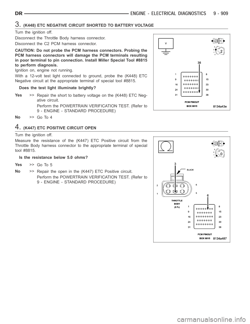
3.(K448) ETC NEGATIVE CIRCUIT SHORTED TO BATTERY VOLTAGE
Turn the ignition off.
Disconnect the Throttle Body harness connector.
Disconnect the C2 PCM harness connector.
CAUTION: Do not probe the PCM harness connectors. Probing the
PCM harness connectors will damage the PCM terminals resulting
in poor terminal to pin connection. Install Miller Special Tool #8815
to perform diagnosis.
Ignition on, engine not running.
With a 12-volt test light connected to ground, probe the (K448) ETC
Negative circuit at the appropriate terminal of special tool #8815.
Does the test light illuminate brightly?
Ye s>>
Repair the short to battery voltage on the (K448) ETC Neg-
ative circuit.
Perform the POWERTRAIN VERIFICATION TEST. (Refer to
9 - ENGINE - STANDARD PROCEDURE)
No>>
Go To 4
4.(K447) ETC POSITIVE CIRCUIT OPEN
Turn the ignition off.
Measure the resistance of the (K447) ETC Positive circuit from the
Throttle Body harness connector to the appropriate terminal of special
tool #8815.
Is the resistance below 5.0 ohms?
Ye s>>
Go To 5
No>>
Repair the open in the (K447) ETC Positive circuit.
Perform the POWERTRAIN VERIFICATION TEST. (Refer to
9 - ENGINE - STANDARD PROCEDURE)
Page 224 of 5267

When Monitored:
With the ignition on and the ETC Motor is not in Limp Home mode.
Set Condition:
When the PCM detects an internal error or a short between the ETC Motor - and ETC Motor + circuits in the
ETC Motor Driver. One trip fault. ETC light is flashing.
Possible Causes
THROTTLE PLATE / BORE INSPECTION
(K447) ETC POSITIVE CIRCUIT SHORTED TO BATTERY VOLTAGE
(K448) ETC NEGATIVE CIRCUIT SHORTED TO BATTERY VOLTAGE
(K447) ETC POSITIVE CIRCUIT SHORTED TO THE (K448) ETC NEGATIVE CIRCUIT
(K447) ETC POSITIVE CIRCUIT OPEN
(K447) ETC POSITIVE CIRCUIT SHORTED TO GROUND
(K448) ETC NEGATIVE CIRCUIT OPEN
(K448) ETC NEGATIVE CIRCUIT SHORTED TO GROUND
ETC MOTOR
PCM
Always perform the Pre-Diagnostic Troubleshooting procedure before proceeding. (Refer to 9 - ENGINE -
DIAGNOSIS AND TESTING).
Diagnostic Test
1.ACTIVE DTC
Ignition on, engine not running.
NOTE: If the P2118 is intermittent, it is possible that the controller is overheating in extreme hot tempera-
tures, and this is considered a normal protection operation. No repair is necessary.
With a scan tool, read DTCs.
Look closely at the temperatures at which this DTC set.
Is the DTC active at this time?
Ye s>>
Go To 2
No>>
Refer to the INTERMITTENT CONDITION Diagnostic Procedure.
Perform the POWERTRAIN VERIFICATION TEST. (Refer to 9 - ENGINE - STANDARD PROCEDURE)
2.THROTTLE PLATE INSPECTION
Turn the ignition off.
Remove the Air Cleaner Assembly from the Throttle Body.
Check for any signs of a foreign material (ice or dirt) on the Throttle Plateor in the bore causing the Throttle Plate
to stick.
Were any signs of foreign material or scoring of the throttle plate or bore found?
Ye s>>
Remove the debris if possible or replace the Throttle Body Assembly. Disconnect the Battery when
replacing the Throttle Body Assembly. After installation is complete, use a scan tool and select the ETC
RELEARN function.
Perform the POWERTRAIN VERIFICATION TEST. (Refer to 9 - ENGINE - STANDARD PROCEDURE)
No>>
Go To 3
Page 225 of 5267

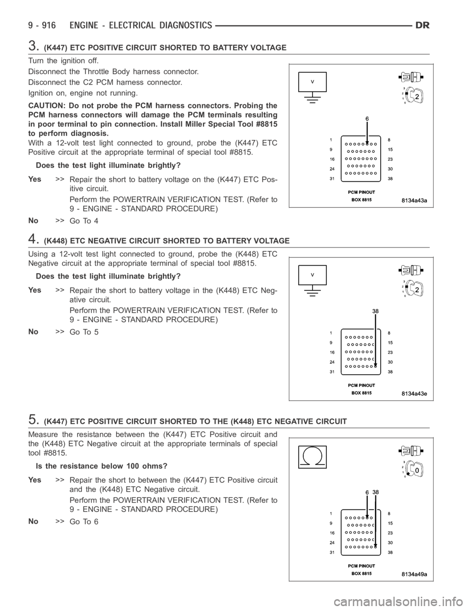
3.(K447) ETC POSITIVE CIRCUIT SHORTED TO BATTERY VOLTAGE
Turn the ignition off.
Disconnect the Throttle Body harness connector.
Disconnect the C2 PCM harness connector.
Ignition on, engine not running.
CAUTION: Do not probe the PCM harness connectors. Probing the
PCM harness connectors will damage the PCM terminals resulting
in poor terminal to pin connection. Install Miller Special Tool #8815
to perform diagnosis.
With a 12-volt test light connected to ground, probe the (K447) ETC
Positive circuit at the appropriate terminal of special tool #8815.
Does the test light illuminate brightly?
Ye s>>
Repair the short to battery voltage on the (K447) ETC Pos-
itive circuit.
Perform the POWERTRAIN VERIFICATION TEST. (Refer to
9 - ENGINE - STANDARD PROCEDURE)
No>>
Go To 4
4.(K448) ETC NEGATIVE CIRCUIT SHORTED TO BATTERY VOLTAGE
Using a 12-volt test light connected to ground, probe the (K448) ETC
Negative circuit at the appropriate terminal of special tool #8815.
Does the test light illuminate brightly?
Ye s>>
Repair the short to battery voltage in the (K448) ETC Neg-
ative circuit.
Perform the POWERTRAIN VERIFICATION TEST. (Refer to
9 - ENGINE - STANDARD PROCEDURE)
No>>
Go To 5
5.(K447) ETC POSITIVE CIRCUIT SHORTED TO THE (K448) ETC NEGATIVE CIRCUIT
Measure the resistance between the (K447) ETC Positive circuit and
the (K448) ETC Negative circuit at the appropriate terminals of special
tool #8815.
Istheresistancebelow100ohms?
Ye s>>
Repair the short to between the (K447) ETC Positive circuit
and the (K448) ETC Negative circuit.
Perform the POWERTRAIN VERIFICATION TEST. (Refer to
9 - ENGINE - STANDARD PROCEDURE)
No>>
Go To 6
Page 228 of 5267

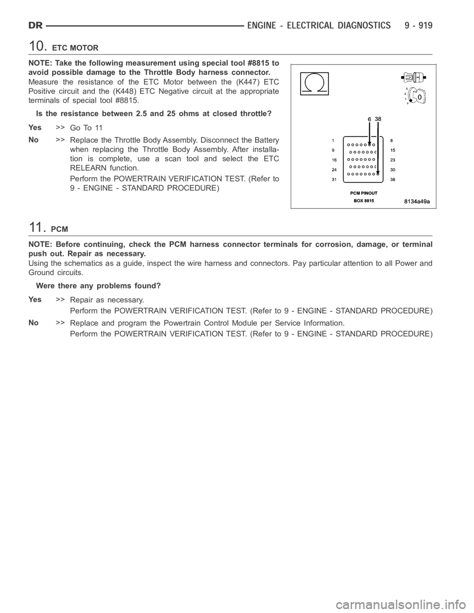
10.ETC MOTOR
NOTE: Take the following measurement using special tool #8815 to
avoid possible damage to the Throttle Body harness connector.
Measure the resistance of the ETC Motor between the (K447) ETC
Positive circuit and the (K448) ETC Negative circuit at the appropriate
terminals of special tool #8815.
Is the resistance between 2.5 and 25 ohms at closed throttle?
Ye s>>
Go To 11
No>>
Replace the Throttle Body Assembly. Disconnect the Battery
when replacing the Throttle Body Assembly. After installa-
tion is complete, use a scan tool and select the ETC
RELEARN function.
Perform the POWERTRAIN VERIFICATION TEST. (Refer to
9 - ENGINE - STANDARD PROCEDURE)
11 .PCM
NOTE: Before continuing, check the PCM harness connector terminals for corrosion, damage, or terminal
push out. Repair as necessary.
Using the schematics as a guide, inspect the wire harness and connectors. Pay particular attention to all Power and
Ground circuits.
Were there any problems found?
Ye s>>
Repair as necessary.
Perform the POWERTRAIN VERIFICATION TEST. (Refer to 9 - ENGINE - STANDARD PROCEDURE)
No>>
Replace and program the Powertrain Control Module per Service Information.
Perform the POWERTRAIN VERIFICATION TEST. (Refer to 9 - ENGINE - STANDARD PROCEDURE)
Page 236 of 5267

When Monitored:
With the ignition on and no other APPS No.1 DTCs present.
Set Condition:
When APP Sensor No.1 voltage is too high. Engine will additionally idle if the brake pedal is pressed or has
failed. Acceleration rate and Engine output are limited. One trip fault and the code will set within 5 seconds.
ETC light is flashing.
Possible Causes
(K23) APP SENSOR NO.1 SIGNAL CIRCUIT SHORTED TO BATTERY VOLTAGE
(K23) APP SENSOR NO.1 SIGNAL SHORTED TO THE (F855) 5-VOLT SUPPLY CIRCUIT
(K23) APP SENSOR NO.1 SIGNAL SHORTED TO THE (F856) 5-VOLT SUPPLY CIRCUIT
(K167) APP SENSOR NO.1 RETURN CIRCUIT OPEN
APP SENSOR
PCM
Always perform the Pre-Diagnostic Troubleshooting procedure before proceeding. (Refer to 9 - ENGINE -
DIAGNOSIS AND TESTING).
Diagnostic Test
1.APPS NO.1 VOLTAGE ABOVE 4.8 VOLTS
Ignition on, engine not running.
With a scan tool, read the APP Sensor No.1 voltage.
Is the voltage above 4.8 volts?
Ye s>>
Go To 2
No>>
Go To 8
2.ACCELERATOR PEDAL POSITION SENSOR
Turn the ignition off.
Disconnect the APP Sensor harness connector.
Ignition on, engine not running.
With a scan tool, monitor the Accelerator Pedal Position Sensor voltage.
Is the voltage between 4.5 and 5.2 volts?
Ye s>>
Go To 3
No>>
Replace the APP Sensor Assembly per Service Information. After installation is complete, use a scan
tool and select the ETC RELEARN function to relearn the APPS values.
Perform the POWERTRAIN VERIFICATION TEST. (Refer to 9 - ENGINE - STANDARD PROCEDURE)
Page 237 of 5267

3.(K23) APP SENSOR NO.1 SIGNAL CIRCUIT SHORTED TO BATTERY VOLTAGE
Turn the ignition off.
Disconnect the C1, C2, and C3 PCM harness connectors.
Ignition on, engine not running.
Measure the voltage on the (K23) APP Sensor No.1 Signal circuit in the
APP Sensor harness connector.
Is the voltage above 0 volts?
Ye s>>
Repair the short to battery voltage in the (K23) APP Sensor
No.1 Signal circuit.
Perform the POWERTRAIN VERIFICATION TEST. (Refer to
9 - ENGINE - STANDARD PROCEDURE)
No>>
Go To 4
4.(K23) APPS NO.1 SIGNAL CIRCUIT SHORTED TO THE (F855) 5-VOLT SUPPLY CIRCUIT
Turn the ignition off.
Measure the resistance between the (K23) APP Sensor No.1 Signal cir-
cuit and the (F855) 5-volt Supply circuit in the APP Sensor harness con-
nector.
Istheresistancebelow100ohms?
Ye s>>
Repair the short between the (K23) APP Sensor No.1 Sig-
nal circuit and the (F855) 5-volt Supply circuit.
Perform the POWERTRAIN VERIFICATION TEST. (Refer to
9 - ENGINE - STANDARD PROCEDURE)
No>>
Go To 5
5.(K23) APPS NO.1 SIGNAL CIRCUIT SHORTED TO THE (F856) 5-VOLT SUPPLY CIRCUIT
Measure the resistance between the (K23) APP Sensor No.1 Signal cir-
cuit and the (F856) 5-volt Supply circuit in the APP Sensor harness con-
nector.
Istheresistancebelow100ohms?
Ye s>>
Repair the short between the (K23) APP Sensor No.1 Sig-
nal circuit and the (F856) 5-volt Supply circuit.
Perform the POWERTRAIN VERIFICATION TEST. (Refer to
9 - ENGINE - STANDARD PROCEDURE)
No>>
Go To 6