2006 DODGE RAM SRT-10 ignition
[x] Cancel search: ignitionPage 88 of 5267
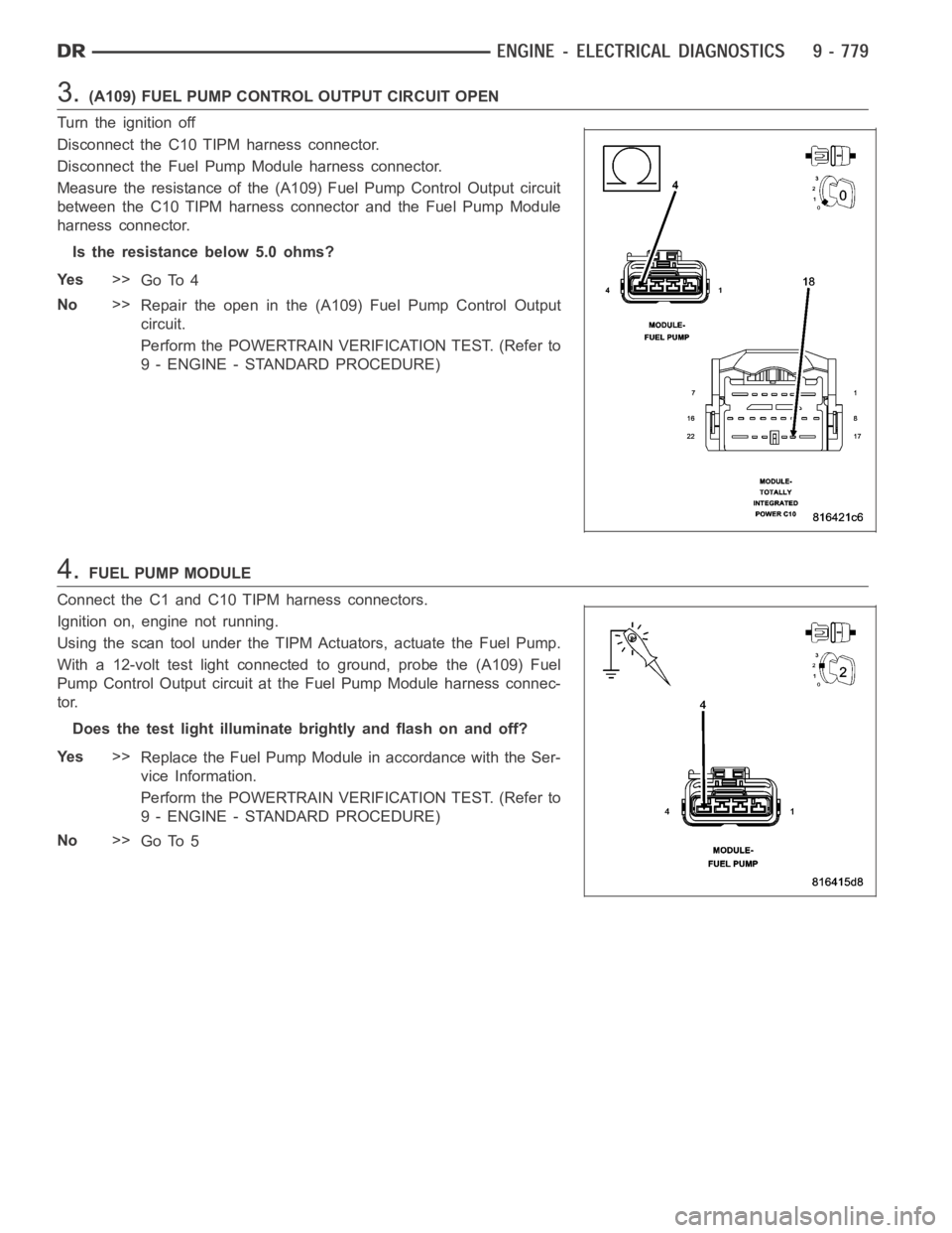
3.(A109) FUEL PUMP CONTROL OUTPUT CIRCUIT OPEN
Turn the ignition off
Disconnect the C10 TIPM harness connector.
Disconnect the Fuel Pump Module harness connector.
Measure the resistance of the (A109) Fuel Pump Control Output circuit
between the C10 TIPM harness connector and the Fuel Pump Module
harness connector.
Is the resistance below 5.0 ohms?
Ye s>>
Go To 4
No>>
Repair the open in the (A109) Fuel Pump Control Output
circuit.
Perform the POWERTRAIN VERIFICATION TEST. (Refer to
9 - ENGINE - STANDARD PROCEDURE)
4.FUEL PUMP MODULE
Connect the C1 and C10 TIPM harness connectors.
Ignition on, engine not running.
Using the scan tool under the TIPM Actuators, actuate the Fuel Pump.
With a 12-volt test light connected to ground, probe the (A109) Fuel
Pump Control Output circuit at the Fuel Pump Module harness connec-
tor.
Does the test light illuminate brightly and flash on and off?
Ye s>>
Replace the Fuel Pump Module in accordance with the Ser-
vice Information.
Perform the POWERTRAIN VERIFICATION TEST. (Refer to
9 - ENGINE - STANDARD PROCEDURE)
No>>
Go To 5
Page 91 of 5267
When Monitored:
With the ignition on. Battery voltage greater than 10.4 volts. TIPM requesting Fuel Pump operation.
Set Condition:
An overcurrent condition is detected in the fuel pump control output circuit. One Trip Fault. Three good trips to
turn off the MIL.
Possible Causes
TERMINAL DAMAGE OR CORROSION
FUEL PUMP MOTOR GROUND HIGH RESISTANCE
(A109) FUEL PUMP CONTROL OUTPUT CIRCUIT HIGH RESISTANCE
FUEL PUMP MOTOR
TIPM
Always perform the Pre-Diagnostic Troubleshooting procedure before proceeding. (Refer to 9 - ENGINE -
DIAGNOSIS AND TESTING).
Diagnostic Test
1.FUEL PUMP OPERATION
Ignition on, engine not running.
With a scan tool in the TIPM Actuators, actuate the Fuel Pump.
Is the Fuel Pump operating?
Ye s>>
Refer to the INTERMITTENT CONDITION Diagnostic Procedure.
Perform the POWERTRAIN VERIFICATION TEST. (Refer to 9 - ENGINE - STANDARD PROCEDURE)
No>>
Go To 2
2.VISUAL AND PHYSICAL CONNECTOR AND TERMINAL INSPECTION
Turn the ignition off.
Disconnect the C10 TIPM harness connector.
Disconnect the Fuel Pump Module harness connector.
Inspect the terminal and connector condition. Check for signs of corrosion build up or damage the would compro-
mise the terminal to controller pin connector.
NOTE: Make sure that all in-line connectors are inspected for corrosion and/or damage.
Visually inspect the wiring harness. Look for any chafed, pierced, pinched or partially broken wires hidden in the
wire insulation.
Were any of the above conditions found?
Ye s>>
Repair or replace as necessary.
Perform the POWERTRAIN VERIFICATION TEST. (Refer to 9 - ENGINE - STANDARD PROCEDURE)
No>>
Go To 3
Page 92 of 5267
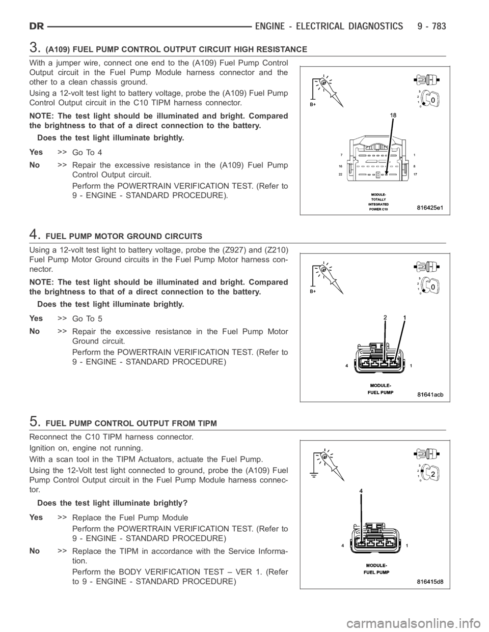
3.(A109) FUEL PUMP CONTROL OUTPUT CIRCUIT HIGH RESISTANCE
With a jumper wire, connect one end to the (A109) Fuel Pump Control
Output circuit in the Fuel Pump Module harness connector and the
other to a clean chassis ground.
Using a 12-volt test light to battery voltage, probe the (A109) Fuel Pump
Control Output circuit in the C10 TIPM harness connector.
NOTE: The test light should be illuminated and bright. Compared
the brightness to that of a direct connection to the battery.
Does the test light illuminate brightly.
Ye s>>
Go To 4
No>>
Repair the excessive resistance in the (A109) Fuel Pump
Control Output circuit.
Perform the POWERTRAIN VERIFICATION TEST. (Refer to
9 - ENGINE - STANDARD PROCEDURE).
4.FUEL PUMP MOTOR GROUND CIRCUITS
Using a 12-volt test light to battery voltage, probe the (Z927) and (Z210)
Fuel Pump Motor Ground circuits in the Fuel Pump Motor harness con-
nector.
NOTE: The test light should be illuminated and bright. Compared
the brightness to that of a direct connection to the battery.
Does the test light illuminate brightly.
Ye s>>
Go To 5
No>>
Repair the excessive resistance in the Fuel Pump Motor
Ground circuit.
Perform the POWERTRAIN VERIFICATION TEST. (Refer to
9 - ENGINE - STANDARD PROCEDURE)
5.FUEL PUMP CONTROL OUTPUT FROM TIPM
Reconnect the C10 TIPM harness connector.
Ignition on, engine not running.
With a scan tool in the TIPM Actuators, actuate the Fuel Pump.
Using the 12-Volt test light connected to ground, probe the (A109) Fuel
Pump Control Output circuit in the Fuel Pump Module harness connec-
tor.
Does the test light illuminate brightly?
Ye s>>
Replace the Fuel Pump Module
Perform the POWERTRAIN VERIFICATION TEST. (Refer to
9 - ENGINE - STANDARD PROCEDURE)
No>>
Replace the TIPM in accordance with the Service Informa-
tion.
Perform the BODY VERIFICATION TEST – VER 1. (Refer
to 9 - ENGINE - STANDARD PROCEDURE)
Page 94 of 5267

Theory of Operation
TheEGRvalvehasapositionsensorandthe EGR position rationality is designed to make sure that the valve
moves freely within its operating range. Closed valve position referencecheck verifies that the valve is within its
allowable upper and lower limits. The EGR position rationality test looksfor a sustained error relative to commanded
valve position.
When Monitored:
Engine running.
Set Condition:
The EGR flow or valve movement is not what is expected. A rationality error has been detected for the EGR
Open Position Performance. Two trip fault.
Possible Causes
EXCESSIVE RESISTANCE IN THE (F856) 5-VOLT SUPPLY CIRCUIT
(K35) EGR SOLENOID CONTROL CIRCUIT OPEN
(K34) EGR SENSOR SIGNAL CIRCUIT SHORTED TO GROUND
EGR SOLENOID ASSEMBLY
PCM
Always perform the Pre-Diagnostic Troubleshooting procedure before proceeding. (Refer to 9 - ENGINE -
DIAGNOSIS AND TESTING).
Diagnostic Test
1.ACTIVE DTC
Ignition on, engine not running.
With a scan tool, read DTCs.
Is the DTC active at this time?
Ye s>>
Go To 2
No>>
Refer to the INTERMITTENT CONDITION Diagnostic Procedure.
Perform the POWERTRAIN VERIFICATION TEST. (Refer to 9 - ENGINE - STANDARD PROCEDURE)
2.EXCESSIVE RESISTANCE IN THE (F856) 5-VOLT SUPPLY CIRCUIT
Turn the ignition off.
Disconnect the EGR Solenoid harness connector.
Disconnect the C1 and C2 PCM harness connectors.
CAUTION: Do not probe the PCM harness connectors. Probing the
PCM harness connectors will damage the PCM terminals resulting
in poor terminal to pin connection. Install Miller Special Tool #8815
to perform diagnosis.
Measure the resistance of the (F856) 5-volt Supply circuit from the EGR
Solenoid harness connector to the appropriate terminal of special tool
#8815.
Is the resistance below 5.0 ohms?
Ye s>>
Go To 3
No>>
Repair the excessive resistance in the (F856) 5-volt Supply
circuit.
Perform the POWERTRAIN VERIFICATION TEST. (Refer to
9 - ENGINE - STANDARD PROCEDURE)
Page 95 of 5267

3.(K35) EGR SOLENOID CONTROL CIRCUIT OPEN
Measure the resistance of the (K35) EGR Solenoid Control circuit from
the EGR Solenoid harness connector to the appropriate terminal of spe-
cial tool #8815.
Is the resistance below 5.0 ohms?
Ye s>>
Go To 4
No>>
Repair the open in the (K35) EGR Solenoid Control circuit.
Perform the POWERTRAIN VERIFICATION TEST. (Refer to
9 - ENGINE - STANDARD PROCEDURE)
4.(K34) EGR SENSOR SIGNAL CIRCUIT SHORTED TO GROUND
Measure the resistance between ground and the (K34) EGR Sensor
Signal circuit in the EGR Solenoid harness connector.
Is the resistance below 5.0 ohms?
Ye s>>
Repair the short to ground in the (K34) EGR Sensor Signal
circuit.
Perform the POWERTRAIN VERIFICATION TEST. (Refer to
9 - ENGINE - STANDARD PROCEDURE)
No>>
Go To 5
5.EGR SOLENOID ASSEMBLY
Ignition on, engine not running.
With the scan tool, actuate the EGR Solenoid.
Allow the EGR Solenoid to actuate for at least 15 seconds.
Feel the EGR Solenoid for operation.
Stop actuation.
Does EGR Solenoid operate while actuating and then turn off when actuationtest is stopped?
a. Yes
Go To 6
No>>
Replace the EGR Solenoid Assembly per Service Information.
Perform the POWERTRAIN VERIFICATION TEST. (Refer to 9 - ENGINE - STANDARD PROCEDURE)
Page 98 of 5267
For a complete wiring diagramRefer to Section 8W.
Theory of Operation
When all criteria has been met, power is supplied to each MDS Solenoid when the engine is making a transition
from 8 cylinder mode to 4 cylinder mode. By actuating the solenoid, oil pressure is raised to the pair of lifters that
coincide with each particular solenoid. The oil pressure pushes in the locking pins that allows the lifter to collapse,
decoupling the valves and camshaft.
When Monitored:
Transition from 8 to 4 cylinder mode.
Set Condition:
The MDS fails to active and take place for cylinder 1. One trip fault.
Possible Causes
(K451) MDS SOLENOID NO.1 CONTROL SHORT TO GROUND
(K451) MDS SOLENOID NO.1 CONTROL OPEN
(Z42) GROUND CIRCUIT OPEN
INSUFFICIENT OIL PRESSURE ACTING ON THE LIFTER LOCKING PINS
OIL PASSAGES RESTRICTED
LIFTER
MDS SOLENOID NO.1
PCM
Always perform the Pre-Diagnostic Troubleshooting procedure before proceeding. (Refer to 9 - ENGINE -
DIAGNOSIS AND TESTING).
Diagnostic Test
1.ACTIVE DTC
Ignition on, engine not running.
With a scan tool, read DTCs.
Is the DTC active at this time?
Ye s>>
Go To 2
No>>
Refer to the INTERMITTENT CONDITION Diagnostic Procedure.
Perform the POWERTRAIN VERIFICATION TEST. (Refer to 9 - ENGINE - STANDARD PROCEDURE)
Page 99 of 5267
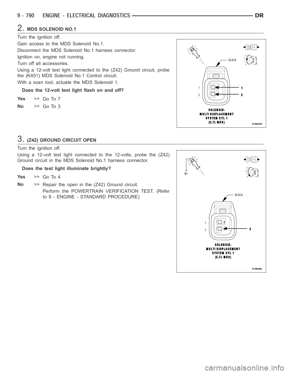
2.MDS SOLENOID NO.1
Turn the ignition off.
Gain access to the MDS Solenoid No.1.
Disconnect the MDS Solenoid No.1 harness connector.
Ignition on, engine not running.
Turn off all accessories.
Using a 12-volt test light connected to the (Z42) Ground circuit, probe
the (K451) MDS Solenoid No.1 Control circuit.
With a scan tool, actuate the MDS Solenoid 1.
Does the 12-volt test light flash on and off?
Ye s>>
Go To 7
No>>
Go To 3
3.(Z42) GROUND CIRCUIT OPEN
Turn the ignition off.
Using a 12-volt test light connected to the 12-volts, probe the (Z42)
Ground circuit in the MDS Solenoid No.1 harness connector.
Does the test light illuminate brightly?
Ye s>>
Go To 4
No>>
Repair the open in the (Z42) Ground circuit.
Perform the POWERTRAIN VERIFICATION TEST. (Refer
to 9 - ENGINE - STANDARD PROCEDURE)
Page 101 of 5267
6.PCM
NOTE: Before continuing, check the PCM harness connector terminals for corrosion, damage, or terminal
push out. Repair as necessary.
Using the schematics as a guide, inspect the wire harness and connectors. Pay particular attention to all Power and
Ground circuits.
Were there any problems found?
Ye s>>
Repair as necessary.
Perform the POWERTRAIN VERIFICATION TEST. (Refer to 9 - ENGINE - STANDARD PROCEDURE)
No>>
Replace and program the Powertrain Control Module per Service Information.
Perform the POWERTRAIN VERIFICATION TEST. (Refer to 9 - ENGINE - STANDARD PROCEDURE)
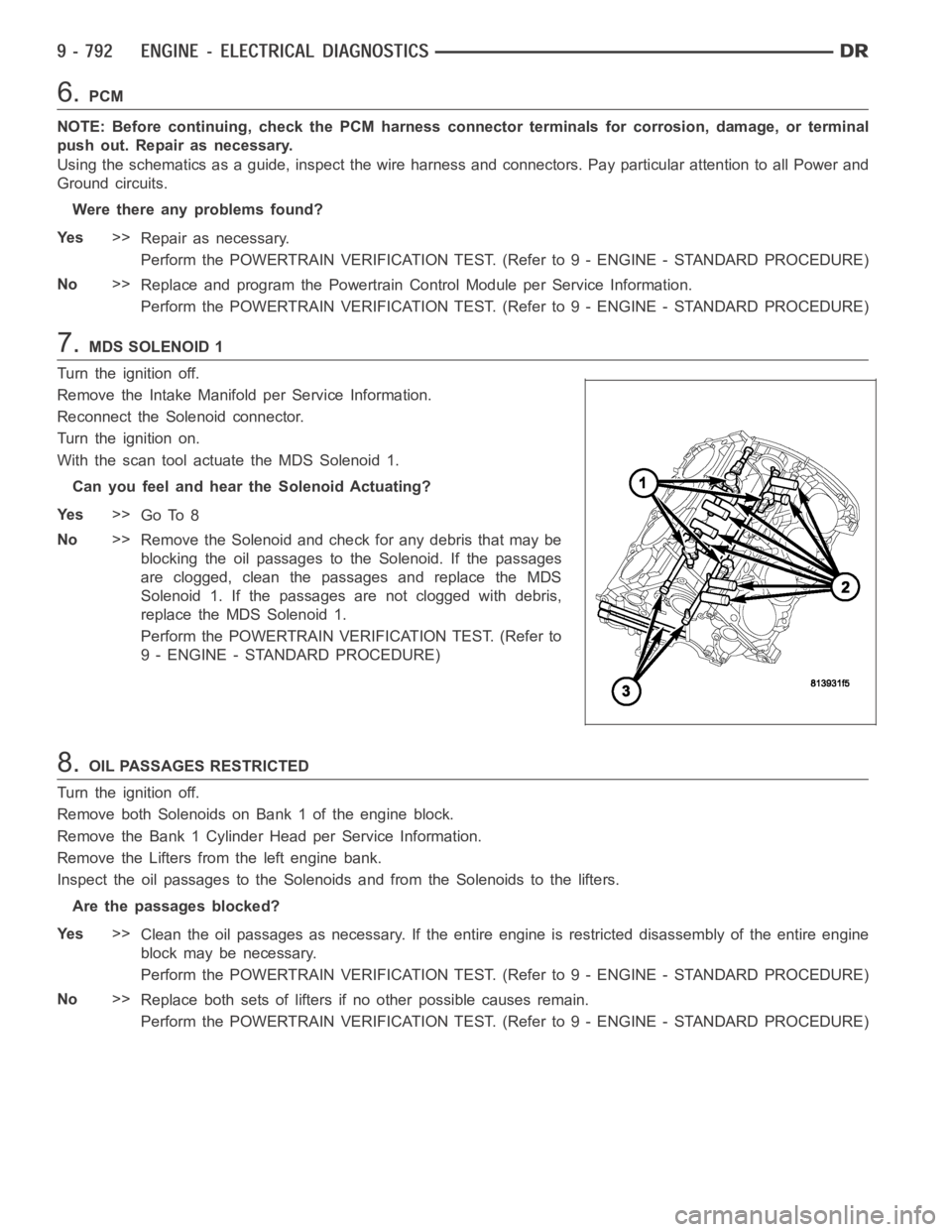
7.MDS SOLENOID 1
Turn the ignition off.
Remove the Intake Manifold per Service Information.
Reconnect the Solenoid connector.
Turn the ignition on.
With the scan tool actuate the MDS Solenoid 1.
Can you feel and hear the Solenoid Actuating?
Ye s>>
Go To 8
No>>
Remove the Solenoid and check for any debris that may be
blocking the oil passages to the Solenoid. If the passages
are clogged, clean the passages and replace the MDS
Solenoid 1. If the passages are not clogged with debris,
replace the MDS Solenoid 1.
Perform the POWERTRAIN VERIFICATION TEST. (Refer to
9 - ENGINE - STANDARD PROCEDURE)
8.OIL PASSAGES RESTRICTED
Turn the ignition off.
Remove both Solenoids on Bank 1 of the engine block.
Remove the Bank 1 Cylinder Head per Service Information.
Remove the Lifters from the left engine bank.
Inspect the oil passages to the Solenoids and from the Solenoids to the lifters.
Are the passages blocked?
Ye s>>
Clean the oil passages as necessary. If the entire engine is restricted disassembly of the entire engine
block may be necessary.
Perform the POWERTRAIN VERIFICATION TEST. (Refer to 9 - ENGINE - STANDARD PROCEDURE)
No>>
Replace both sets of lifters if no other possible causes remain.
Perform the POWERTRAIN VERIFICATION TEST. (Refer to 9 - ENGINE - STANDARD PROCEDURE)