2006 DODGE RAM SRT-10 fuel type
[x] Cancel search: fuel typePage 2252 of 5267
6. Perform fuel pressure release procedure. Refer to
Fuel Pressure Release Procedure.
7. Disconnect negative battery cable from battery.
8. Clean fitting of any foreign material before disas-
sembly.
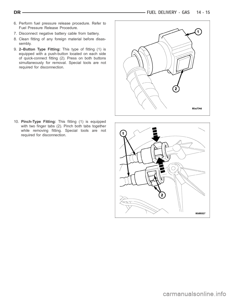
9.2–Button Type Fitting:This type of fitting (1) is
equipped with a push-button located on each side
of quick-connect fitting (2). Press on both buttons
simultaneously for removal. Special tools are not
required for disconnection.
10.Pinch-Type Fitting:This fitting (1) is equipped
with two finger tabs (2). Pinch both tabs together
while removing fitting. Special tools are not
required for disconnection.
Page 2253 of 5267
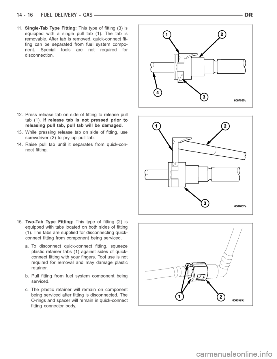
11 .Single-Tab Type Fitting:This type of fitting (3) is
equipped with a single pull tab (1). The tab is
removable. After tab is removed, quick-connect fit-
ting can be separated from fuel system compo-
nent. Special tools are not required for
disconnection.
12. Press release tab on side of fitting to release pull
tab (1).If release tab is not pressed prior to
releasing pull tab, pull tab will be damaged.
13. While pressing release tab on side of fitting, use
screwdriver (2) to pry up pull tab.
14. Raise pull tab until it separates from quick-con-
nect fitting.
15.Tw o - Ta b Ty p e F i t t i n g :This type of fitting (2) is
equipped with tabs located on both sides of fitting
(1). The tabs are supplied for disconnecting quick-
connect fitting from component being serviced.
a. To disconnect quick-connect fitting, squeeze
plastic retainer tabs (1) against sides of quick-
connect fitting with your fingers. Tool use is not
required for removal and may damage plastic
retainer.
b. Pull fitting from fuel system component being
serviced.
c. The plastic retainer will remain on component
being serviced after fitting is disconnected. The
O-rings and spacer will remain in quick-connect
fitting connector body.
Page 2254 of 5267
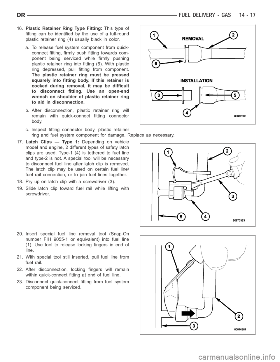
16.Plastic Retainer Ring Type Fitting:This type of
fitting can be identified by the use of a full-round
plastic retainer ring (4) usually black in color.
a. To release fuel systemcomponent from quick-
connect fitting, firmly push fitting towards com-
ponent being serviced while firmly pushing
plastic retainer ring into fitting (6). With plastic
ring depressed, pull fitting from component.
The plastic retainer ring must be pressed
squarely into fitting body. If this retainer is
cocked during removal, it may be difficult
to disconnect fitting. Use an open-end
wrench on shoulder of plastic retainer ring
to aid in disconnection.
b. After disconnection, plastic retainer ring will
remain with quick-connect fitting connector
body.
c. Inspect fitting connector body, plastic retainer
ring and fuel system component for damage. Replace as necessary.
17.Latch Clips — Type 1:Depending on vehicle
model and engine, 2 different types of safety latch
clips are used. Type-1 (4) is tethered to fuel line
and type-2 is not. A special tool will be necessary
to disconnect fuel line after latch clip is removed.
The latch clip may be used on certain fuel line/
fuel rail connection, or to join fuel lines together.
18. Pry up on latch clip with a screwdriver (3).
19. Slide latch clip toward fuel rail while lifting with
screwdriver.
20. Insert special fuel line removal tool (Snap-On
number FIH 9055-1 or equivalent) into fuel line
(1). Use tool to release locking fingers in end of
line.
21. With special tool still inserted, pull fuel line from
fuel rail.
22. After disconnection, locking fingers will remain
within quick-connect fitting at end of fuel line.
23. Disconnect quick-connect fitting from fuel system
component being serviced.
Page 2255 of 5267
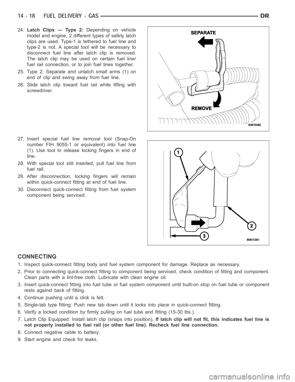
24.Latch Clips — Type 2:Depending on vehicle
model and engine, 2 different types of safety latch
clips are used. Type-1 is tethered to fuel line and
type-2 is not. A special tool will be necessary to
disconnect fuel line after latch clip is removed.
The latch clip may be used on certain fuel line/
fuel rail connection, or to join fuel lines together.
25. Type 2: Separate and unlatch small arms (1) on
end of clip and swing away from fuel line.
26. Slide latch clip toward fuel rail while lifting with
screwdriver.
27. Insert special fuel line removal tool (Snap-On
number FIH 9055-1 or equivalent) into fuel line
(1). Use tool to release locking fingers in end of
line.
28. With special tool still inserted, pull fuel line from
fuel rail.
29. After disconnection, locking fingers will remain
within quick-connect fitting at end of fuel line.
30. Disconnect quick-connect fitting from fuel system
component being serviced.
CONNECTING
1. Inspect quick-connect fitting body and fuel system component for damage. Replace as necessary.
2. Prior to connecting quick-connect fitting to component being serviced, check condition of fitting and component.
Clean parts with a lint-free cloth. Lubricate with clean engine oil.
3. Insert quick-connect fitting intofuel tube or fuel system component until built-on stop on fuel tube or component
rests against back of fitting.
4. Continue pushing until a click is felt.
5. Single-tab type fitting: Push new tab down until it locks into place in quick-connect fitting.
6. Verify a locked condition by firmly pulling on fuel tube and fitting (15-30 lbs.).
7. Latch Clip Equipped: Install latch clip (snaps into position).If latch clip will not fit, this indicates fuel line is
not properly installed to fuel rail (or other fuel line). Recheck fuel lineconnection.
8. Connect negative cable to battery.
9. Start engine and check for leaks.
Page 2386 of 5267
OPERATION
High-pressure fuel is supplied from the injection pump, through a high-pressure fuel line, into a fuel rail, through
high-pressure lines, through steel connectors and into the solenoid actuated fuel injector. The ECM actuates the
solenoid causing the needle valve to rise and fuel flows through the spray holes in the nozzle tip into the combus-
tion chamber.
Each fuel injector is connected to the fuel rail by a high-pressure fuel line and a steel connector. This steel con-
nector is positioned into the cylinder head and sealed with an O-ring. The connector is retained in the cylinder head
by a nut (fitting) that is threaded into the cylinder head.
The torquing force of this threaded nut (fitting) provides a sealing pressure between the fuel line connector and the
fuel injector.Retaining nut torque is very critical.If the nut (fitting) is under torqued, the mating surfaces will not
seal and a high-pressure fuel leak will result. If the fitting is over torqued, the connector and injector will deform and
also cause a high-pressure fuel leak. This leak will be inside the cylinderhead and will not be visible. The result will
be a possible fuel injector miss-fire and low power, or a no-start condition.
The fuel injectors use hole type nozzles. High-pressure flows into the side of the injector, the ECM activates the
solenoid causing the injector needle to lift and fuel to be injected. The clearances in the nozzle bore are extremely
small and any dirt or contaminants will cause the injector to stick. Because of this, it is very important to do a
thorough cleaning of any lines before opening up any fuel system component. Always cover or cap any open fuel
connections before a fuel system repair is performed.
Each fuel injector connector tube contains an edge filter that is designedto break up small contaminants before
entering the fuel injector.The edge filters are not a substitute for proper cleaning and covering of allfuel
system components during repair.
The bottom of each fuel injector is sealed to the cylinder head with a1.5mmthick copper shim (gasket). The correct
thickness shim must always be re-installed after removing an injector.
Fuel pressure in the injector circuit decreases after injection. The injector needle valve is immediately closed and
fuel flow into the combustion chamber is stopped. Exhaust gases are prevented from entering the injector nozzle by
the needle valve.
REMOVAL
CAUTION: Refer to Cleaning Fuel System Parts.
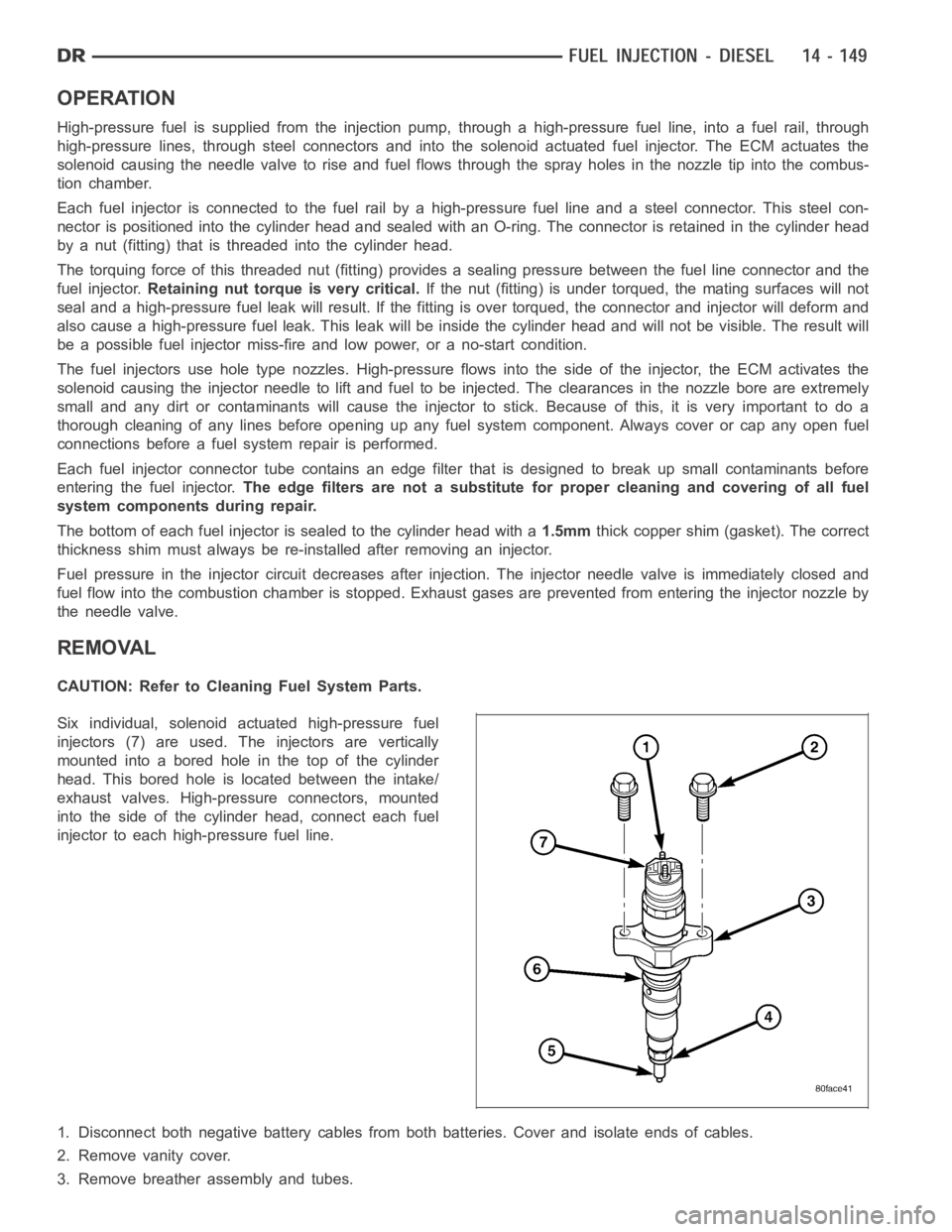
Six individual, solenoid actuated high-pressure fuel
injectors (7) are used. The injectors are vertically
mounted into a bored hole in the top of the cylinder
head. This bored hole is located between the intake/
exhaust valves. High-pressure connectors, mounted
into the side of the cylinder head, connect each fuel
injector to each high-pressure fuel line.
1. Disconnect both negative battery cables from both batteries. Cover andisolate ends of cables.
2. Remove vanity cover.
3. Remove breather assembly and tubes.
Page 5196 of 5267
CATALYST MONITOR
To comply with clean air regulations, vehicles are equipped with catalytic converters. These converters reduce the
emission of hydrocarbons, oxides of nitrogen and carbon monoxide.
Normal vehicle miles or engine misfire can cause a catalyst to decay. This can increase vehicle emissions and
deteriorate engine performance, driveability and fuel economy.
The catalyst monitor uses dual oxygen sensors (O2S’s) to monitor the efficiency of the converter. The dual O2S’s
sensor strategy is based on the fact that as a catalyst deteriorates, its oxygen storage capacity and its efficiency are
both reduced. By monitoring the oxygen storage capacity of a catalyst, itsefficiency can be indirectly calculated. The
upstream O2S is used to detect the amount of oxygen in the exhaust gas beforethe gas enters the catalytic con-
verter. The PCM calculates the A/F mixture from the output of the O2S. A low voltage indicates high oxygen content
(lean mixture). A high voltage indicates a low content of oxygen (rich mixture).
When the upstream O2S detects a lean condition, there is an abundance of oxygen in the exhaust gas. A function-
ing converter would store this oxygen so it can use it for the oxidation of HCand CO. As the converter absorbs the
oxygen, there will be a lack of oxygen downstream of the converter. The output of the downstream O2S will indicate
limited activity in this condition.
As the converter loses the ability to store oxygen, the condition can be detected from the behavior of the down-
stream O2S. When the efficiency drops, no chemical reaction takes place. This means the concentration of oxygen
will be the same downstream as upstream. The output voltage of the downstream O2S copies the voltage of the
upstream sensor. The only difference is a time lag (seen by the PCM) betweenthe switching of the O2S’s.
To monitor the system, the number of lean-to-rich switches of upstream anddownstream O2S’s is counted. The
ratio of downstream switches to upstream switches is used to determine whether the catalyst is operating properly.
An effective catalyst will have fewer downstream switches than it has upstream switches i.e., a ratio closer to zero.
For a totally ineffective catalyst, this ratio will be one-to-one, indicating that no oxidation occurs in the device.
The system must be monitored so that when catalyst efficiency deteriorates and exhaust emissions increase to over
the legal limit, the MIL will be illuminated.
TRIP DEFINITION
The term “Trip” has different meanings depending on what the circumstances are. If the MIL (Malfunction Indicator
Lamp) is OFF, a Trip is defined as when the Oxygen Sensor Monitor and the Catalyst Monitor have been completed
in the same drive cycle.
When any Emission DTC is set, the MIL on the dash is turned ON. When the MIL is ON, it takes 3 good trips to turn
the MIL OFF. In this case, it depends on what type of DTC is set to know what a “Trip” is.
For the Fuel Monitor or Mis-Fire Monitor (continuous monitor), the vehicle must be operated in the “Similar Condition
Window” for a specified amount of time to be considered a Good Trip.
If a Non-Continuous OBDII Monitor fails twice in a row and turns ON the MIL, re-running that monitor which previ-
ously failed, on the next start-up and passing the monitor, is considered tobeaGoodTrip.Thesewillincludethe
following:
Oxygen Sensor
Catalyst Monitor
Purge Flow Monitor
Leak Detection Pump Monitor (if equipped)
EGR Monitor (if equipped)
Oxygen Sensor Heater Monitor
If any other Emission DTC is set (not an OBDII Monitor), a Good Trip is considered to be when the Oxygen Sensor
Monitor and Catalyst Monitor have been completed; or 2 Minutes of engine run time if the Oxygen Sensor Monitor
or Catalyst Monitor have been stopped from running.
It can take up to 2 Failures in a row to turn on the MIL. After the MIL is ON, it takes3GoodTripstoturntheMIL
OFF. After the MIL is OFF, the PCM will self-erase the DTC after 40 Warm-up cycles. A Warm-up cycle is counted
when the ECT (Engine Coolant Temperature Sensor) has crossed 160°F (71.1C) and has risen by at least 40°F
(4.4°C) since the engine has been started.