2006 DODGE RAM SRT-10 fuel type
[x] Cancel search: fuel typePage 1912 of 5267
12. Place a rag over the compression test tool fitting. Crank the engine for2–3 seconds to purge any fuel that may
have drained into the cylinder when the injector was removed.
13. Connect the compression test gauge.
14. Crank the engine for 5 seconds and record the pressure reading. Repeat this step three times and calculate the
average of the three readings.
NOTE: The minimum cylinder pressure is 350 psi. Cylinder pressure should be within 20% from cylinder to
cylinder.
15. Combustion pressure leakage can be checked if cylinder pressure is below the specification. Perform the leak-
age test procedure on each cylinder according to the tester manufacturer instructions.
16. Upon completion of the test check and erase any engine related fault codes.
CYLINDER COMBUSTION PRESSURE LEAKAGE
The combustion pressure leakage test provides an accurate means for determining engine condition.
Combustion pressure leakage testing will detect:
Exhaust and intake valve leaks (improper seating).
Leaks between adjacent cylinders or into water jacket.
Any causes for combustion/compression pressure loss
1. Start and operate the engine until it attains normal operating temperature.
2. Disconnect injector harness connectors.
3. Disconnect breather tube and breather drain tube from valve cover.
4. Remove the cylinder head cover. (Refer to 9 - ENGINE/CYLINDER HEAD/CYLINDER HEAD COVER(S) -
REMOVAL)
5. Disconnect harness from injectors.
6. Remove the cylinder head cover carrier gasket. (Refer to 9 - ENGINE/CYLINDER HEAD/CYLINDER HEAD
COVER(S) - REMOVAL)
7. BringthecylindertobetestedtoTDC.
8. Remove the high pressure fuel line between the cylinder head and the fuelrail for the cylinder to be tested.
9. Install capping Tool 9011 onto the rail.
10. Remove the high pressure connector nut and high pressure connector with Tool 9015.
11. Remove the exhaust and intake rocker lever.
12. Use Tool # 9010 to remove the injector and copper sealing washer.
13. Install compression test Tool # 9007 into the injector bore.
14. Connect the leakage tester and perform the leakage test procedure on each cylinder according to the tester
manufacturer’s instructions.
15. Upon completion of the test check and erase any engine related fault codes.
STANDARD PROCEDURE
STANDARD PROCEDURE - FORM-IN-PLACE GASKETS AND SEALERS
There are numerous places where form-in-place gaskets are used on the engine. Care must be taken when apply-
ing form-in-place gaskets to assure obtaining the desired results.Do not use form-in-place gasket material
unless specified.Bead size, continuity, and location are of great importance. Too thin a bead can result in leakage
while too much can result in spill-overwhich can break off and obstruct fluid feed lines. A continuous bead of the
proper width is essential to obtain a leak-free gasket.
There are numerous types of form-in-place gasket materials that are used in the engine area. Mopar
Engine RTV
GEN II, Mopar
ATF-RTV, and MoparGasket Maker gasket materials, each have different properties and can not
be used in place of the other.
MOPAR
ENGINE RTV GEN II
Page 1914 of 5267
3. Place a shop towel around the fuel injectors to catch any fluid that may possibly be under pressure in the cyl-
inder head. Remove the fuel injectors (Refer to 14 - FUEL SYSTEM/FUEL INJECTION/FUEL INJECTOR -
REMOVAL).
4. With all injectors removed, rotatethe crankshaft using the crankshaftbarring tool (PN 7471–B).
5. Identify the fluid in the cylinders (coolant, fuel, oil, etc.).
6. Be sure all fluid has been removed from the cylinders.
7. Repair engine or components as necessary to prevent this problem from occurring again.
8. Squirt a small amount of engine oil into the cylinders to lubricate the walls. This will prevent damage on restart.
9. Install fuel injectors (Refer to 14 - FUEL SYSTEM/FUEL INJECTION/FUEL INJECTOR - INSTALLATION).
10. Drain engine oil. Remove and discard the oil filter (Refer to 9 - ENGINE/LUBRICATION/OIL FILTER -
REMOVAL).
11. Installthedrainplug.Tightentheplugto50Nꞏm(37ft.lbs.)torque.
12. Install a new oil filter (Refer to 9 - ENGINE/LUBRICATION/OIL FILTER - INSTALLATION).
13. Fill engine crankcase with the specified amount and grade of oil (Referto LUBRICATION & MAINTENANCE/
FLUID TYPES - SPECIFICATIONS).
14. Connect the negative cable(s) to the battery.
15. Start the engine and check for any leaks.
REMOVAL - ENGINE
1. Disconnect both battery negative cables.
2. Disconnect engine grid heater harness at grid
heater relays.
3. Disconnect electrical connections from rear of alter-
nator.
4. Recover A/C refrigerant. (Refer to 24 - HEATING &
AIR CONDITIONING/PLUMBING - STANDARD
PROCEDURE).
5. Raise vehicle on a hoist.
6. Drain engine coolant (Refer to 7 - COOLING -
STANDARD PROCEDURE).
7. Remove engine oil drain plug and drain engine oil.
8. Reinstall drain plug. Tighten to 50 Nꞏm (37 ft. lbs.)
torque.
9. Lower the vehicle.
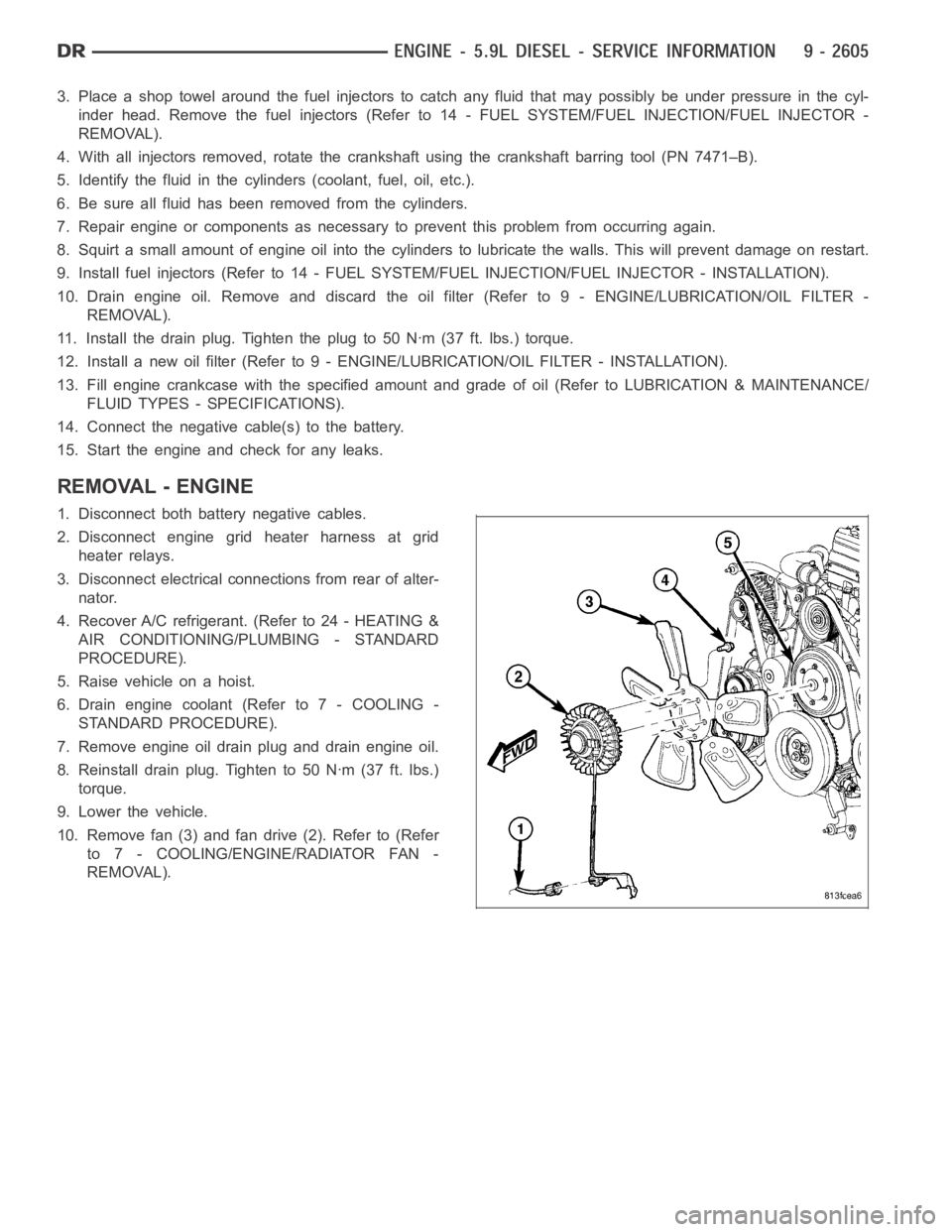
10. Remove fan (3) and fan drive (2). Refer to (Refer
to 7 - COOLING/ENGINE/RADIATOR FAN -
REMOVAL).
Page 2002 of 5267
OIL
STANDARD PROCEDURE
STANDARD PROCEDURE - ENGINE OIL LEVEL
CAUTION: Do not overfill crankcase with engine
oil, oil foaming and oil pressure loss can result.
To ensure proper lubrication of an engine, the engine
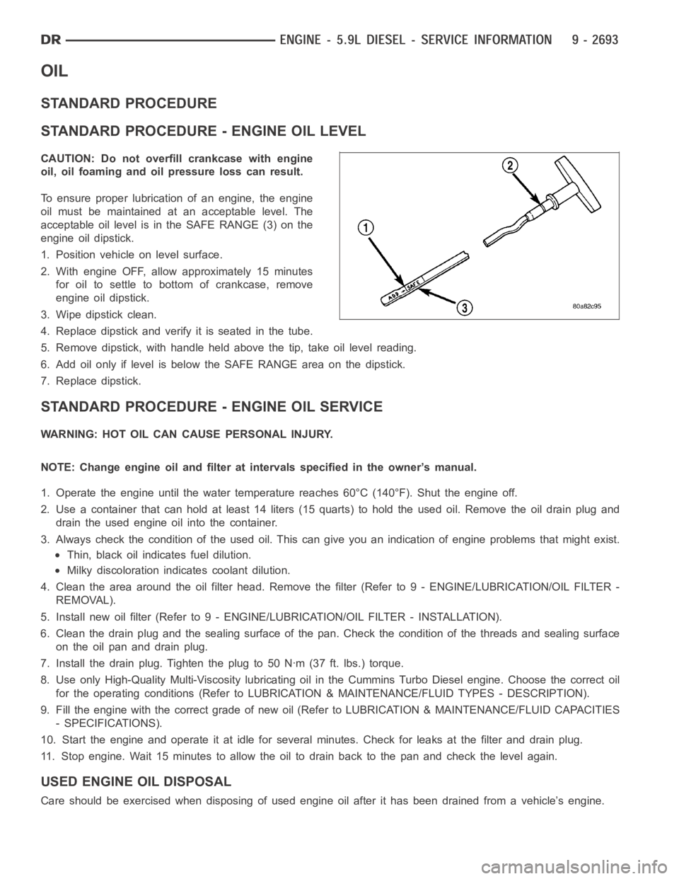
oil must be maintained at an acceptable level. The
acceptable oil level is in the SAFE RANGE (3) on the
engine oil dipstick.
1. Position vehicle on level surface.
2. With engine OFF, allow approximately 15 minutes
for oil to settle to bottom of crankcase, remove
engine oil dipstick.
3. Wipe dipstick clean.
4. Replace dipstick and verify it is seated in the tube.
5. Remove dipstick, with handle held above the tip, take oil level reading.
6. Add oil only if level is below the SAFE RANGE area on the dipstick.
7. Replace dipstick.
STANDARD PROCEDURE - ENGINE OIL SERVICE
WARNING: HOT OIL CAN CAUSE PERSONAL INJURY.
NOTE: Change engine oil and filter at intervals specified in the owner’s manual.
1. Operate the engine until the water temperature reaches 60°C (140°F). Shut the engine off.
2. Use a container that can hold at least 14 liters (15 quarts) to hold the used oil. Remove the oil drain plug and
drain the used engine oil into the container.
3. Always check the condition of the used oil. This can give you an indication of engine problems that might exist.
Thin, black oil indicates fuel dilution.
Milky discoloration indicates coolant dilution.
4. Clean the area around the oil filter head. Remove the filter (Refer to 9 - ENGINE/LUBRICATION/OIL FILTER -
REMOVAL).
5. Install new oil filter (Refer to 9 - ENGINE/LUBRICATION/OIL FILTER - INSTA L L AT I O N ) .
6. Clean the drain plug and the sealing surface of the pan. Check the condition of the threads and sealing surface
on the oil pan and drain plug.
7. Install the drain plug. Tighten the plug to 50 Nꞏm (37 ft. lbs.) torque.
8. Use only High-Quality Multi-Viscosity lubricating oil in the Cummins Turbo Diesel engine. Choose the correct oil
for the operating conditions (Refer to LUBRICATION & MAINTENANCE/FLUID TYPES - DESCRIPTION).
9. Fill the engine with the correct grade of new oil (Refer to LUBRICATION & MAINTENANCE/FLUID CAPACITIES
- SPECIFICATIONS).
10. Start the engine and operate it at idle for several minutes. Check for leaks at the filter and drain plug.
11. Stop engine. Wait 15 minutes to allow the oil to drain back to the pan and check the level again.
USED ENGINE OIL DISPOSAL
Care should be exercised when disposing of used engine oil after it has beendrained from a vehicle’s engine.
Page 2022 of 5267
ENGINE - 8.3L - SERVICE INFORMATION
DESCRIPTION
The engine is an 8.3 Liter (505 CID), 10-cylinder, 90°
V-type, lightweight, single-cam, overhead valve
engine. This engine is designed for premium unleaded
fuel.
The crankshaft is forged steel. The cylinder block and
cylinder heads are aluminum. The firing order is 1-10-
9-4-3-6-5-8-7-2. The cylinders are numbered from
front to rear as follows:
on the left bank - 1, 3, 5, 7, 9
on the right bank - 2, 4, 6, 8, 10
Vehicle Identification Number
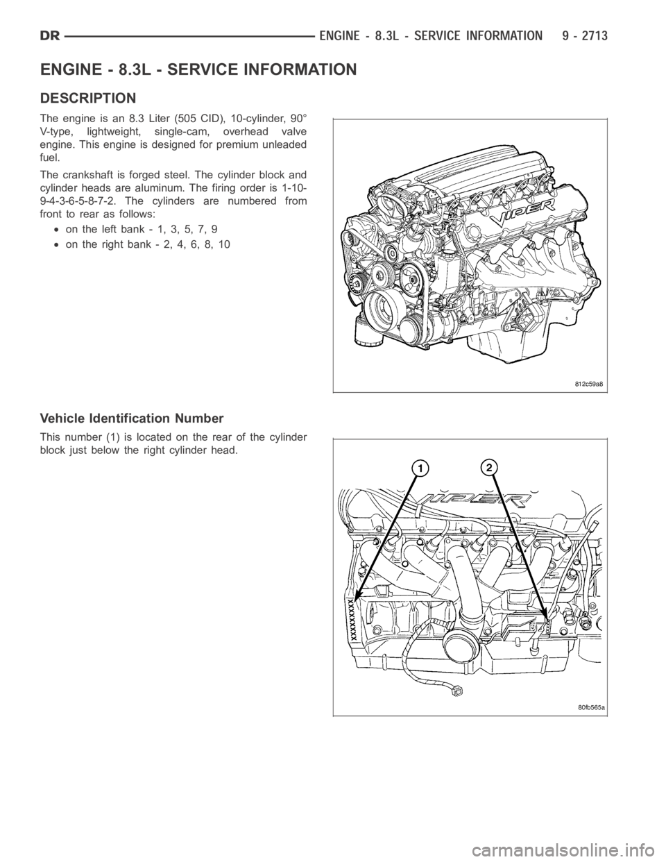
This number (1) is located on the rear of the cylinder
block just below the right cylinder head.
Page 2088 of 5267
OIL
STANDARD PROCEDURE
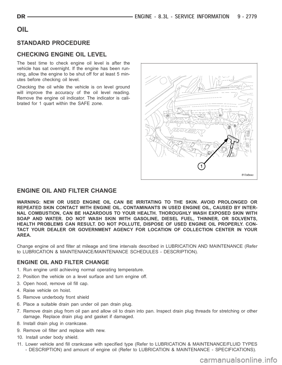
CHECKING ENGINE OIL LEVEL
The best time to check engine oil level is after the
vehicle has sat overnight. If the engine has been run-
ning, allow the engine to be shut off for at least 5 min-
utes before checking oil level.
Checking the oil while the vehicle is on level ground
will improve the accuracy of the oil level reading.
Remove the engine oil indicator. The indicator is cali-
brated for 1 quart within the SAFE zone.
ENGINE OIL AND FILTER CHANGE
WARNING: NEW OR USED ENGINE OIL CAN BE IRRITATING TO THE SKIN. AVOID PROLONGED OR
REPEATED SKIN CONTACT WITH ENGINE OIL. CONTAMINANTS IN USED ENGINE OIL, CAUSED BY INTER-
NAL COMBUSTION, CAN BE HAZARDOUS TO YOUR HEALTH. THOROUGHLY WASH EXPOSED SKIN WITH
SOAP AND WATER. DO NOT WASH SKIN WITH GASOLINE, DIESEL FUEL, THINNER, OR SOLVENTS,
HEALTH PROBLEMS CAN RESULT. DO NOT POLLUTE, DISPOSE OF USED ENGINE OIL PROPERLY. CON-
TACT YOUR DEALER OR GOVERNMENT AGENCY FOR LOCATION OF COLLECTION CENTER INYOUR
AREA.
Change engine oil and filter at mileage and time intervals described in LUBRICATION AND MAINTENANCE (Refer
to LUBRICATION & MAINTENANCE/MAINTENANCE SCHEDULES - DESCRIPTION).
ENGINE OIL AND FILTER CHANGE
1. Run engine until achieving normal operating temperature.
2. Position the vehicle on a level surface and turn engine off.
3. Open hood, remove oil fill cap.
4. Raise vehicle on hoist.
5. Remove underbody front shield
6. Place a suitable drain pan under oil pan drain plug.
7. Remove drain plug from oil pan and allow oil to drain into pan. Inspect drain plug threads for stretching or other
damage. Replace drain plug and gasket if damaged.
8. Install drain plug in crankcase.
9. Remove oil filter and replace with new.
10. Install under body shield.
11. Lower vehicle and fill crankcase with specified type (Refer to LUBRICATION & MAINTENANCE/FLUID TYPES
- DESCRIPTION) and amount of engine oil (Refer to LUBRICATION & MAINTENANCE - SPECIFICATIONS).
Page 2249 of 5267
LINES, FUEL
DESCRIPTION
Also refer to Quick-Connect Fittings.
WARNING: The fuel system may be under a constant pressure (even with the engine off). Before servicing
any fuel system hoses, fittings, lines, or most components, fuel system pressure must be released. Refer to
the fuel system pressure release procedure.
The lines/tubes/hoses used on fuel injected vehicles are of a special construction. This is due to the higher fuel
pressures and the possibility of contaminated fuel in this system. If it isnecessary to replace these lines/tubes/
hoses, only those marked EFM/EFI may be used.
If equipped:The hose clamps used to secure rubber hoses on fuel injected vehicles are ofa special rolled edge
construction. This construction is used to prevent the edge of the clamp from cutting into the hose. Only these rolled
edge type clamps may be used in this system. All other types of clamps may cutinto the hoses and cause high-
pressure fuel leaks.
Use new original equipment type hose clamps.
Page 2250 of 5267
FITTING-QUICK CONNECT
DESCRIPTION
Different types of quick-connect fittings are used to attach the various fuel system components, lines and tubes.
These are: a single-button type, a two-button type, a pinch type, a single-tab type, a two-tab type or a plastic
retainer ring type. Some are equipped with safety latch clips. Some may require the use of a special tool for dis-
connection and removal. (Refer to 14 - FUEL SYSTEM/FUEL DELIVERY/QUICK CONNECT FITTING - STANDARD
PROCEDURE)
CAUTION: Before separating a quick-connect fitting, pay attention to whattypeoffittingisbeingusedby
referring to Quick-Connect Fitting Removal. This will prevent unnecessary fitting or fitting latch breakage.
CAUTION: The interior components (O-rings, clips) of quick-connect fittings are not serviced separately, but
new plastic spacers and latches are available for some types. If service parts are not available, do not
attempt to repair the damaged fitting or fuel line (tube). If repair is necessary, replace the complete fuel line
(tube) assembly.
STANDARD PROCEDURE - QUICK-CONNECT FITTINGS
Different types of quick-connect fittings are used to attach the various fuel system components, lines and tubes.
These are: a single-button type, a two-button type, a pinch type, a single-tab type, a two-tab type or a plastic
retainer ring type. Some are equipped with safety latch clips. Some may require the use of a special tool for dis-
connection and removal.
DISCONNECTING
WARNING: The fuel system is under a constant pressure (even with engine off). Before servicing any fuel
system hose, fitting or line, fuel system pressure must be released. Referto fuel system pressure release
procedure.
CAUTION: Before separating a quick-connect fitting, pay attention to whattypeoffittingisbeingusedby
referring to Quick-Connect Fitting Removal. This will prevent unnecessary fitting or fitting latch breakage.
CAUTION: The interior components (O-rings, clips) of quick-connect fittings are not serviced separately, but
new plastic spacers and latches are available for some types. If service parts are not available, do not
attempt to repair the damaged fitting or fuel line (tube). If repair is necessary, replace the complete fuel line
(tube) assembly.
1. Perform fuel pressure release procedure. Refer to Fuel Pressure Release Procedure.
2. Disconnect negative battery cable from battery.
3. Clean fitting of any foreign material before disassembly.
Page 2251 of 5267
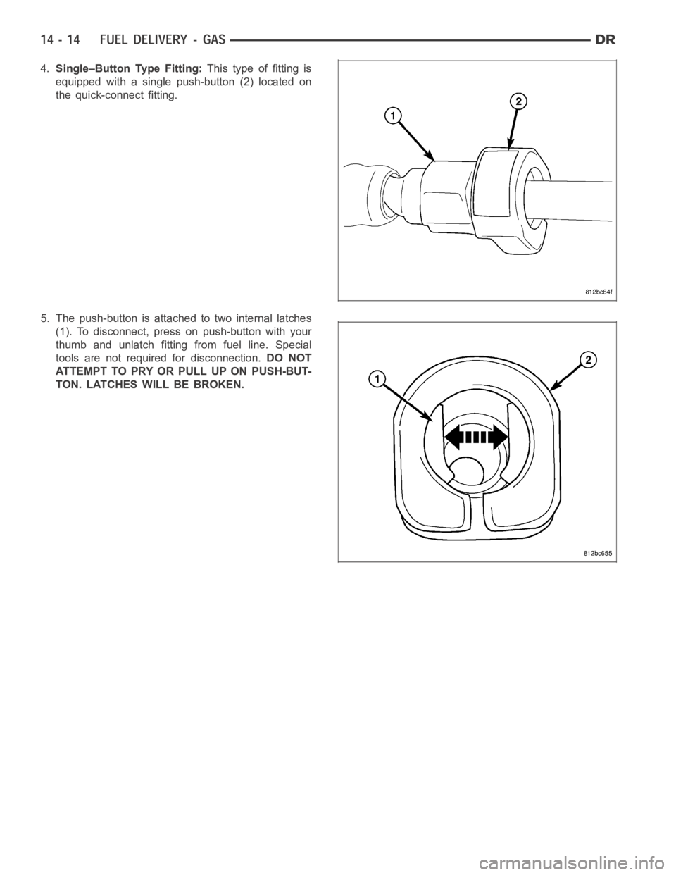
4.Single–Button Type Fitting:This type of fitting is
equipped with a single push-button (2) located on
the quick-connect fitting.
5. The push-button is attached to two internal latches
(1). To disconnect, press on push-button with your
thumb and unlatch fitting from fuel line. Special
tools are not required for disconnection.DO NOT
ATTEMPT TO PRY OR PULL UP ON PUSH-BUT-
TON. LATCHES WILL BE BROKEN.