2006 DODGE RAM SRT-10 check oil
[x] Cancel search: check oilPage 2892 of 5267
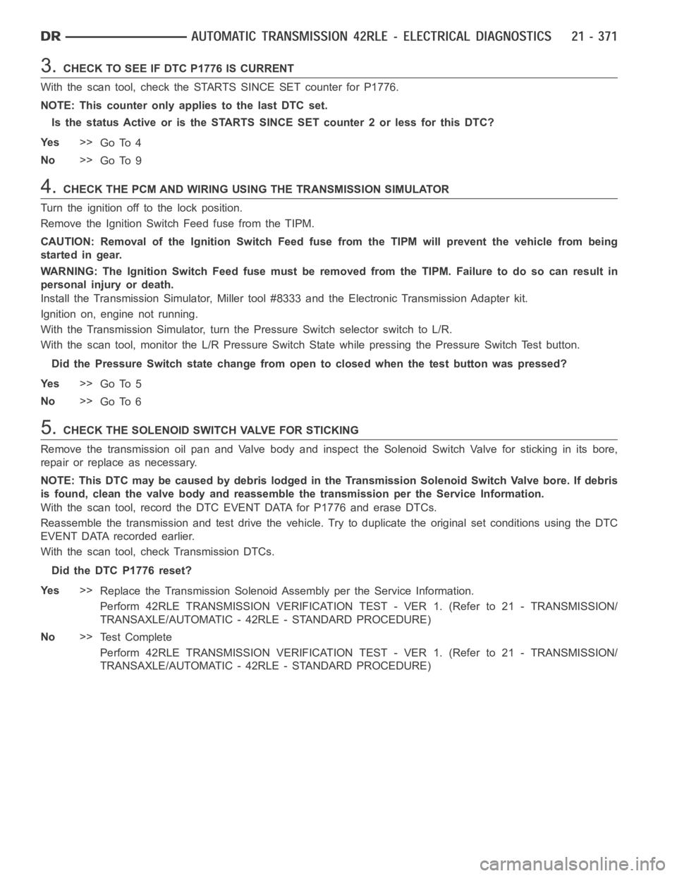
3.CHECK TO SEE IF DTC P1776 IS CURRENT
With the scan tool, check the STARTS SINCE SET counter for P1776.
NOTE: This counter only applies to the last DTC set.
Is the status Active or is the STARTS SINCE SET counter 2 or less for this DTC?
Ye s>>
Go To 4
No>>
Go To 9
4.CHECK THE PCM AND WIRING USING THE TRANSMISSION SIMULATOR
Turn the ignition off to the lock position.
Remove the Ignition Switch Feed fuse from the TIPM.
CAUTION: Removal of the Ignition Switch Feed fuse from the TIPM will prevent the vehicle from being
startedingear.
WARNING: The Ignition Switch Feed fuse must be removed from the TIPM. Failure to do so can result in
personal injury or death.
Install the Transmission Simulator,Miller tool #8333 and the ElectronicTransmission Adapter kit.
Ignition on, engine not running.
With the Transmission Simulator, turn the Pressure Switch selector switchtoL/R.
With the scan tool, monitor the L/R Pressure Switch State while pressing the Pressure Switch Test button.
Did the Pressure Switch state change from open to closed when the test button was pressed?
Ye s>>
Go To 5
No>>
Go To 6
5.CHECK THE SOLENOID SWITCH VALVE FOR STICKING
Remove the transmission oil pan and Valve body and inspect the Solenoid Switch Valve for sticking in its bore,
repair or replace as necessary.
NOTE: This DTC may be caused by debris lodged in the Transmission Solenoid Switch Valve bore. If debris
is found, clean the valve body and reassemble the transmission per the Service Information.
With the scan tool, record the DTC EVENT DATA for P1776 and erase DTCs.
Reassemble the transmission and test drive the vehicle. Try to duplicate the original set conditions using the DTC
EVENT DATA recorded earlier.
With the scan tool, check Transmission DTCs.
Did the DTC P1776 reset?
Ye s>>
Replace the Transmission Solenoid Assembly per the Service Information.
Perform 42RLE TRANSMISSION VERIFICATION TEST - VER 1. (Refer to 21 - TRANSMISSION/
TRANSAXLE/AUTOMATIC - 42RLE - STANDARD PROCEDURE)
No>>
Te s t C o m p l e t e
Perform 42RLE TRANSMISSION VERIFICATION TEST - VER 1. (Refer to 21 - TRANSMISSION/
TRANSAXLE/AUTOMATIC - 42RLE - STANDARD PROCEDURE)
Page 2910 of 5267
page page
AUTOMATIC TRANSMISSION 42RLE - SERVICE
INFORMATION
DESCRIPTION ............................... 391
OPERATION ................................. 393
DIAGNOSIS AND TESTING
AUTOMATIC TRANSMISSION ............... 398
ROAD TEST ............................... 399
HYDRAULIC PRESSURE TESTS............ 400
CLUTCH AIR PRESSURE TESTS........... 402
FLUID LEAKAGE.......................... 403
STANDARD PROCEDURE - ALUMINUM
THREAD REPAIR .......................... 404
REMOVAL ................................... 404
DISASSEMBLY .............................. 406
ASSEMBLY .................................. 428
INSTALLATION .............................. 451
SCHEMATICS AND DIAGRAMS
42RLE - WITHOUT VARIABLE LINE
PRESSURE............................... 455
42RLE - WITH VARIABLE LINE PRESSURE . . 469
SPECIFICATIONS
42RLE AUTOMATIC TRANSMISSION ........ 479
SPECIAL TOOLS
42RLE AUTOMATIC TRANSMISSION ........ 481
ACCUMULATOR
DESCRIPTION ............................... 485
OPERATION ................................. 486
SEAL-ADAPTER HOUSING
REMOVAL ................................... 487
INSTALLATION .............................. 487
BEARINGS
ADJUSTMENTS
BEARING ADJUSTMENT PROCEDURES.... 488
MECHANISM-BRAKE TRANSMISSION SHIFT
INTERLOCK
DESCRIPTION ............................... 489
OPERATION ................................. 489
DIAGNOSIS AND TESTING - BRAKE
TRANSMISSION SHIFT INTERLOCK ......... 489
ADJUSTMENTS - BRAKE TRANSMISSION
SHIFT INTERLOCK ......................... 489
CLUTCHES-DRIVING
DESCRIPTION ............................... 491
OPERATION ................................. 491
SEAL-EXTENSION HOUSING
REMOVAL ................................... 492
INSTALLATION .............................. 492
FLUID AND FILTER
DIAGNOSIS AND TESTING
CAUSES OF BURNT FLUID ................. 493EFFECTS OF INCORRECT FLUID LEVEL . . . . 493
FLUID CONTAMINATION ................... 493
STANDARD PROCEDURE
FLUID LEVEL CHECK...................... 493
FLUID/FILTER SERVICE .................... 494
TRANSMISSION FILL ...................... 495
CABLE-GEARSHIFT
DIAGNOSIS AND TESTING - GEARSHIFT
CABLE .................................... 496
REMOVAL ................................... 496
INSTALLATION .............................. 497
ADJUSTMENTS - GEARSHIFT CABLE ......... 498
CLUTCHES-HOLDING
DESCRIPTION ............................... 499
OPERATION ................................. 499
ASSEMBLY-INPUT CLUTCH
DISASSEMBLY .............................. 500
ASSEMBLY .................................. 509
SENSOR-INPUT SPEED
DESCRIPTION ............................... 523
OPERATION ................................. 523
REMOVAL ................................... 523
INSTALLATION .............................. 524
SENSOR-VARIABLE LINE PRESSURE
DESCRIPTION ............................... 525
OPERATION ................................. 525
REMOVAL ................................... 525
INSTALLATION .............................. 526
PUMP-OIL
DESCRIPTION ............................... 527
OPERATION ................................. 527
DISASSEMBLY .............................. 527
ASSEMBLY .................................. 529
SENSOR-OUTPUT SPEED
DESCRIPTION ............................... 530
OPERATION ................................. 530
REMOVAL ................................... 530
INSTALLATION .............................. 531
GEARTRAIN-PLANETARY
DESCRIPTION ............................... 532
OPERATION ................................. 532
SEAL-OIL PUMP
REMOVAL ................................... 533
INSTALLATION .............................. 533
SOLENOID-PRESSURE CONTROL
DESCRIPTION ............................... 534
OPERATION ................................. 534
REMOVAL ................................... 534
INSTALLATION .............................. 535
Page 2924 of 5267
OVERDRIVE CLUTCH
Apply air pressure to the overdrive clutch apply passage and watch for the push/pull piston to move forward. The
piston should return to its starting position when the air pressure is removed.
REVERSE CLUTCH
Apply air pressure to the reverse clutch apply passage and watch for the push/pull piston to move rearward. The
piston should return to its starting position when the air pressure is removed.
LOW/REVERSE CLUTCH
Apply air pressure to the low/reverse clutch feed hole passage. Look in thearea where the low/reverse piston con-
tacts the first separator plate. Watch carefully for the piston to move forward. The piston should return to its original
position after the air pressure is removed.
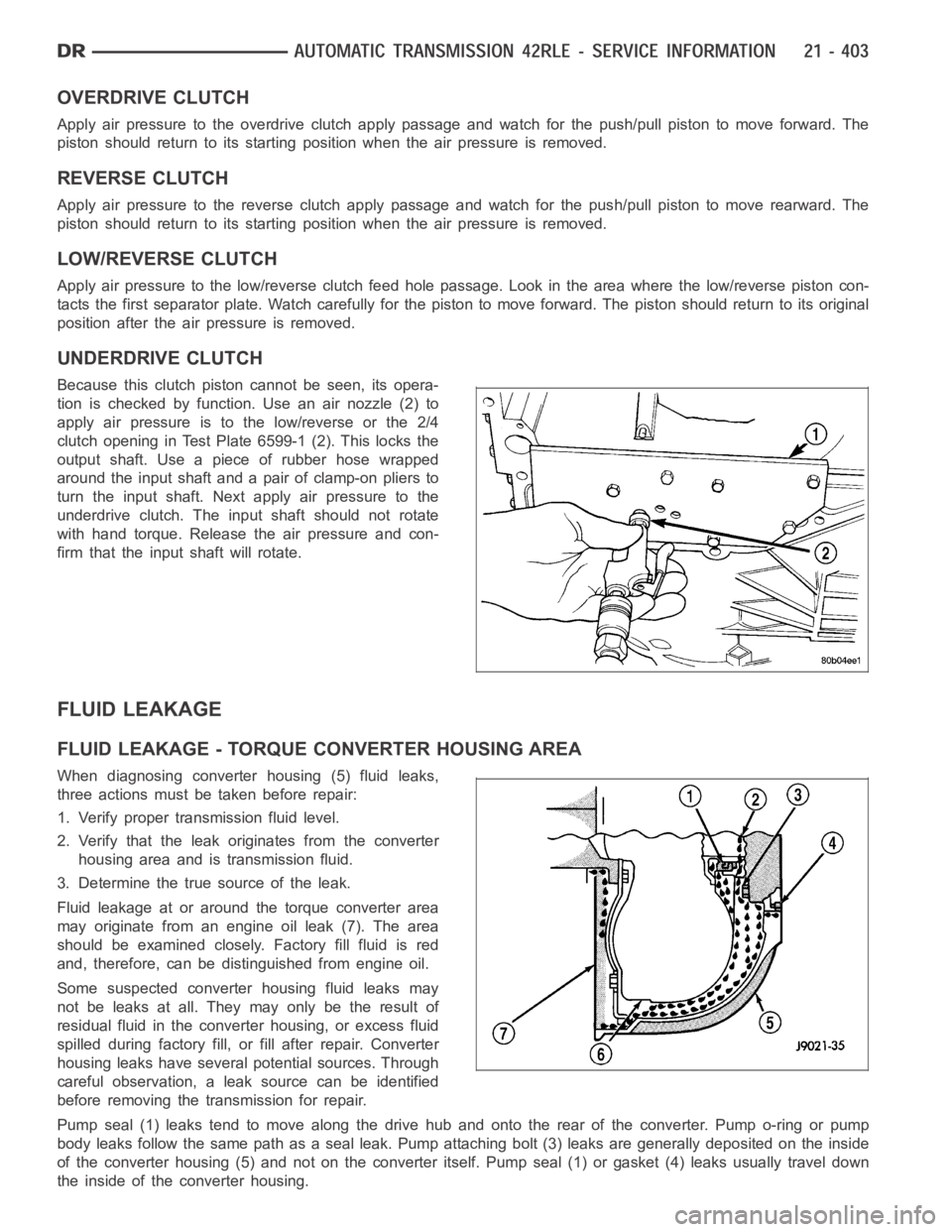
UNDERDRIVE CLUTCH
Because this clutch piston cannot be seen, its opera-
tion is checked by function. Use an air nozzle (2) to
apply air pressure is to the low/reverse or the 2/4
clutch opening in Test Plate 6599-1 (2). This locks the
output shaft. Use a piece of rubber hose wrapped
around the input shaft and a pair of clamp-on pliers to
turn the input shaft. Next apply air pressure to the
underdrive clutch. The input shaft should not rotate
with hand torque. Release the air pressure and con-
firm that the input shaft will rotate.
FLUID LEAKAGE
FLUID LEAKAGE - TORQUE CONVERTER HOUSING AREA
When diagnosing converter housing (5) fluid leaks,
three actions must be taken before repair:
1. Verify proper transmission fluid level.
2. Verify that the leak originates from the converter
housing area and is transmission fluid.
3. Determine the true source of the leak.
Fluid leakage at or around the torque converter area
may originate from an engine oil leak (7). The area
should be examined closely. Factory fill fluid is red
and, therefore, can be distinguished from engine oil.
Some suspected converter housing fluid leaks may
not be leaks at all. They may only be the result of
residual fluid in the converter housing, or excess fluid
spilled during factory fill, or fill after repair. Converter
housing leaks have several potential sources. Through
careful observation, a leak source can be identified
before removing the transmission for repair.
Pump seal (1) leaks tend to move along the drive hub and onto the rear of the converter. Pump o-ring or pump
body leaks follow the same path as a seal leak. Pump attaching bolt (3) leaksare generally deposited on the inside
of the converter housing (5) and not on the converter itself. Pump seal (1) or gasket (4) leaks usually travel down
the inside of the converter housing.
Page 2968 of 5267
NOTE: Before installing the oil pan bolt in the bolt
hole located between the torque converter clutch
on and U/D clutch pressure tap circuits , it will be
necessary to replenish the sealing patch on the
bolt using MOPAR
Lock & Seal Adhesive.
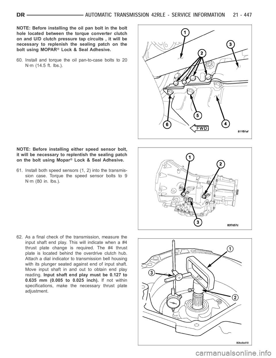
60. Install and torque the oil pan-to-case bolts to 20
Nꞏm (14.5 ft. lbs.).
NOTE: Before installing either speed sensor bolt,
it will be necessary to replentish the sealing patch
on the bolt using Mopar
Lock & Seal Adhesive.
61. Install both speed sensors (1, 2) into the transmis-
sion case. Torque the speed sensor bolts to 9
Nꞏm (80 in. lbs.).
62. As a final check of the transmission, measure the
input shaft end play. This will indicate when a #4
thrust plate change is required. The #4 thrust
plate is located behind the overdrive clutch hub.
Attach a dial indicator to transmission bell housing
with its plunger seated against end of input shaft.
Move input shaft in and out to obtain end play
reading.Input shaft end play must be 0.127 to
0.635 mm (0.005 to 0.025 inch).If not within
specifications, make the necessary thrust plate
adjustment.
Page 2972 of 5267
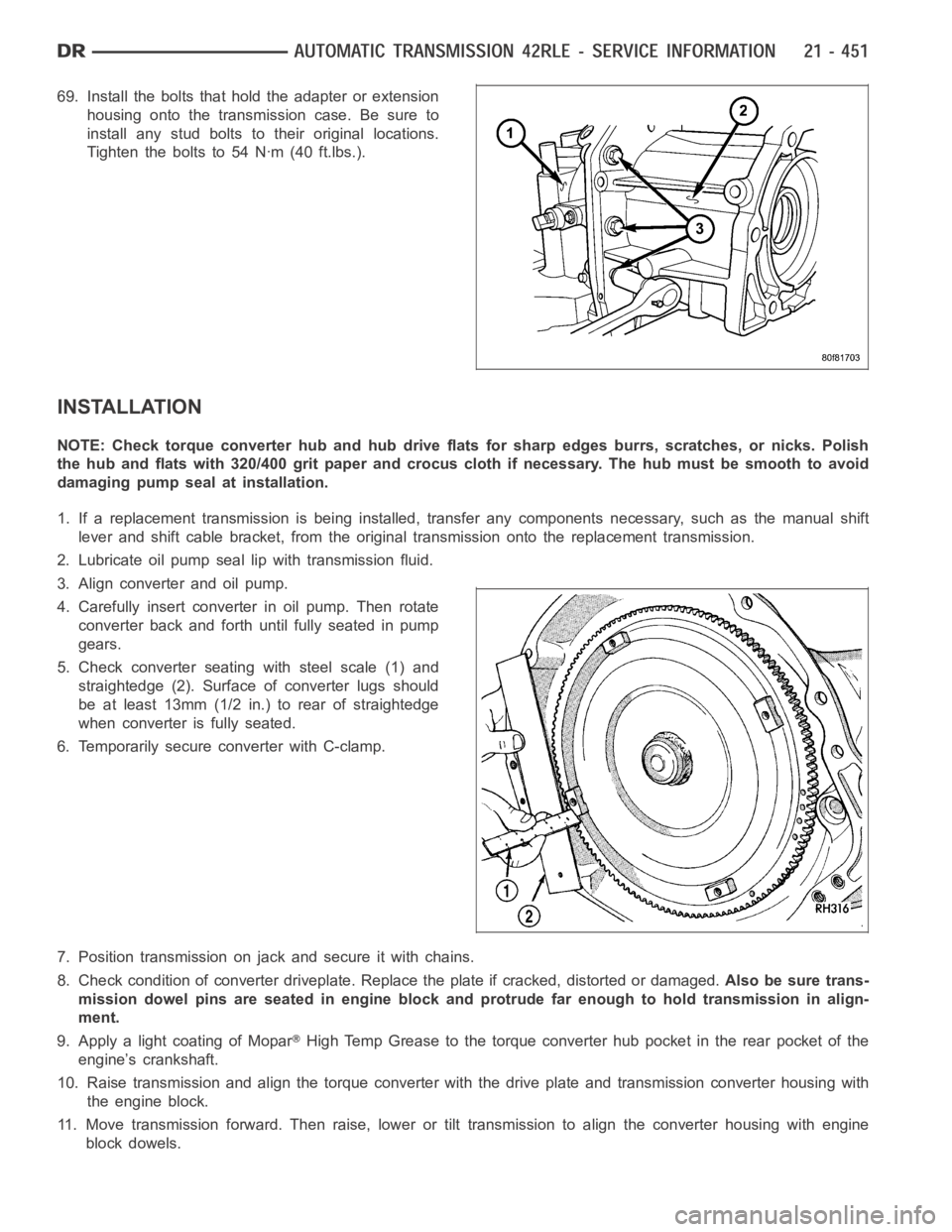
69. Install the bolts that hold the adapter or extension
housing onto the transmission case. Be sure to
install any stud bolts to their original locations.
Tighten the bolts to 54 Nꞏm (40 ft.lbs.).
INSTALLATION
NOTE: Check torque converter hub and hub drive flats for sharp edges burrs,scratches, or nicks. Polish
the hub and flats with 320/400 grit paper and crocus cloth if necessary. Thehub must be smooth to avoid
damaging pump seal at installation.
1. If a replacement transmission is being installed, transfer any components necessary, such as the manual shift
lever and shift cable bracket, from the original transmission onto the replacement transmission.
2. Lubricate oil pump seal lip with transmission fluid.
3. Align converter and oil pump.
4. Carefully insert converter in oil pump. Then rotate
converter back and forth until fully seated in pump
gears.
5. Check converter seating with steel scale (1) and
straightedge (2). Surface of converter lugs should
be at least 13mm (1/2 in.) to rear of straightedge
when converter is fully seated.
6. Temporarily secure converter with C-clamp.
7. Position transmission on jack and secure it with chains.
8. Check condition of converter driveplate. Replace the plate if cracked,distorted or damaged.Also be sure trans-
mission dowel pins are seated in engine block and protrude far enough to holdtransmissioninalign-
ment.
9. Apply a light coating of Mopar
High Temp Grease to the torque converter hub pocket in the rear pocket of the
engine’s crankshaft.
10. Raise transmission and align the torque converter with the drive plateand transmission converter housing with
the engine block.
11. Move transmission forward. Then raise, lower or tilt transmission to align the converter housing with engine
block dowels.
Page 3009 of 5267
BEARINGS
ADJUSTMENTS
BEARING ADJUSTMENT PROCEDURES
Take extreme care when removing andinstalling bearing cups and cones.Use only an arbor press for installa-
tion,as a hammer may not properly align the bearing cup or cone. Burrs or nicks on the bearing seat will give a
false end play reading, while gauging for proper shims. Improperly seatedbearing cup and cones are subject to
low-mileage failure.
Bearing cups and cones should be replaced if they show signs of pitting or heat distress.
If distress is seen on either the cup or bearing rollers, both cup and cone must be replaced.
NOTE: Bearing drag torque specifications must be maintained to avoid premature bearing failures.
Used (original) bearing may lose up to 50 percent of the original drag torque after break-in.
NOTE: All bearing adjustments must be made with no other component interference or gear inter-mesh.
Oil all bearings before checking turning torque.
Page 3014 of 5267
FLUID AND FILTER
DIAGNOSIS AND TESTING
CAUSES OF BURNT FLUID
Burnt, discolored fluid is a result of overheating which has two primary causes.
1. A result of restricted fluid flow through the main and/or auxiliary cooler. This condition is usually the result of a
faulty or improperly installed drainback valve, a damaged oil cooler, or severe restrictions in the coolers and lines
caused by debris or kinked lines.
2. Heavy duty operation with a vehicle not properly equipped for this type of operation. Trailer towing or similar high
load operation will overheat the transmission fluid if the vehicle is improperly equipped. Such vehicles should
have an auxiliary transmission fluid cooler, a heavy duty cooling system,and the engine/axle ratio combination
needed to handle heavy loads.
EFFECTS OF INCORRECT FLUID LEVEL
Alowfluidlevelallowsthepumptotakeinairalongwiththefluid.Airinthe fluid will cause fluid pressures to be
low and develop slower than normal. If the transmission is overfilled, thegears churn the fluid into foam. This aer-
ates the fluid and causing the same conditions occurring with a low level. In either case, air bubbles cause fluid
overheating, oxidation, and varnish buildup which interferes with valveand clutch operation. Foaming also causes
fluid expansion which can result in fluid overflow from the transmission vent or fill tube. Fluid overflow can easily be
mistaken for a leak if inspection is not careful.
FLUID CONTAMINATION
Transmission fluid contamination is generally a result of:
adding incorrect fluid
failure to clean dipstick and fill tube when checking level
engine coolant entering the fluid
internal failure that generates debris
overheat that generates sludge (fluid breakdown)
failure to replace contaminated converter after repair
The use of non-recommended fluids can result in transmission failure. Theusual results are erratic shifts, slippage,
abnormal wear and eventual failure due to fluid breakdown and sludge formation. Avoid this condition by using rec-
ommended fluids only.
The dipstick cap and fill tube should be wiped clean before checking fluid level. Dirt, grease and other foreign mate-
rial on the cap and tube could fall into the tube if not removed beforehand. Take the time to wipe the cap and tube
clean before withdrawing the dipstick.
Engine coolant in the transmission fluid is generally caused by a cooler malfunction. The only remedy is to replace
the radiator as the cooler in the radiator is not a serviceable part. If coolant has circulated through the transmission,
an overhaul is necessary.
The torque converter should also be replaced whenever a failure generatessludge and debris. This is necessary
because normal converter flushing procedures will not remove all contaminants.
STANDARD PROCEDURE
FLUID LEVEL CHECK
The transmission sump has a dipstick to check oil similar to most automatictransmissions. It is located on the left
side of the engine. Be sure to wipe all dirt from dipstick handle before removing.
The torque converter fills in both the PARK and NEUTRAL positions. Place the selector lever in PARK to be sure
that the fluid level check is accurate.The engine should be running at idle speed for at least one minute, with
the vehicle on level ground.At normal operating temperature (approximately 82° C or 180° F), the fluidlevel is
correct if it is in the HOT region (cross-hatched area) on the oil level indicator. The fluid level should be in COLD
region at 21° C (70° F) fluid temperature. Adjust fluid level as necessary.Use only Mopar
ATF+4, Automatic Trans-
mission Fluid.
Page 3015 of 5267
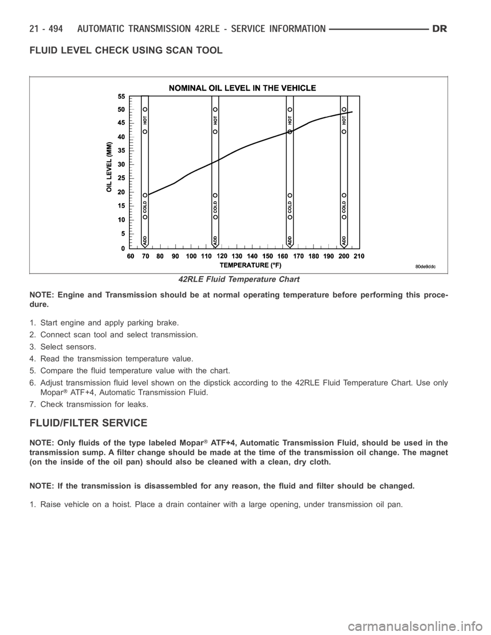
FLUID LEVEL CHECK USING SCAN TOOL
NOTE: Engine and Transmission should be at normal operating temperature before performing this proce-
dure.
1. Start engine and apply parking brake.
2. Connect scan tool and select transmission.
3. Select sensors.
4. Read the transmission temperature value.
5. Compare the fluid temperature value with the chart.
6. Adjust transmission fluid level shown on the dipstick according to the 42RLE Fluid Temperature Chart. Use only
Mopar
ATF+4, Automatic Transmission Fluid.
7. Check transmission for leaks.
FLUID/FILTER SERVICE
NOTE: Only fluids of the type labeled MoparATF+4, Automatic Transmission Fluid, should be used in the
transmission sump. A filter change should be made at the time of the transmission oil change. The magnet
(on the inside of the oil pan) should also be cleaned with a clean, dry cloth.
NOTE: If the transmission is disassembled for any reason, the fluid and filter should be changed.
1. Raise vehicle on a hoist. Place a drain container with a large opening, under transmission oil pan.
42RLE Fluid Temperature Chart