Page 1531 of 5267
ARM-VALVE ROCKER
DESCRIPTION
The rocker arms are steel stampings with an integral roller bearing. The rocker arms incorporate a 2.8 mm (0.11
inch) oil hole in the lash adjuster socket for roller and camshaft lubrication.
REMOVAL
NOTE: Disconnect the battery negative cable to
prevent accidental starter engagement.
1. Remove the cylinder head cover (Refer to 9 -
ENGINE/CYLINDER HEAD/CYLINDER HEAD
COVER(S) - REMOVAL).
2. For rocker arm removal on cylinder No. 4, Rotate
the crankshaft until cylinder No. 1 is at BDC intake
stroke.
3. For rocker arm removal on cylinder No. 1, Rotate
the crankshaft until cylinder No. 1 is at BDC com-
bustion stroke.
4. For rocker arm removal on cylinders No. 3 and No.
5, Rotate the crankshaft until cylinder No. 1 is at
TDC exhaust stroke.
5. For rocker arm removal on cylinders No. 2 and No.
6, Rotate the crankshaft until cylinder No. 1 is at
TDC ignition stroke.
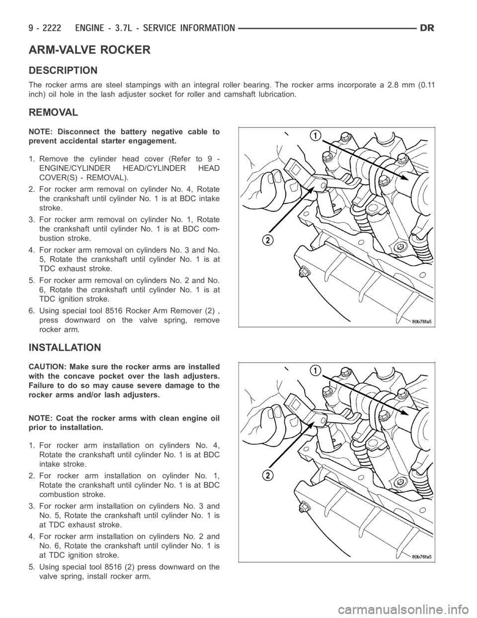
6. Using special tool 8516 Rocker Arm Remover (2) ,
press downward on the valve spring, remove
rocker arm.
INSTALLATION
CAUTION: Make sure the rocker arms are installed
with the concave pocket over the lash adjusters.
Failure to do so may cause severe damage to the
rocker arms and/or lash adjusters.
NOTE: Coat the rocker arms with clean engine oil
prior to installation.
1. For rocker arm installation on cylinders No. 4,
Rotate the crankshaft until cylinder No. 1 is at BDC
intake stroke.
2. For rocker arm installation on cylinder No. 1,
Rotate the crankshaft until cylinder No. 1 is at BDC
combustion stroke.
3. For rocker arm installation on cylinders No. 3 and
No. 5, Rotate the crankshaft until cylinder No. 1 is
at TDC exhaust stroke.
4. For rocker arm installation on cylinders No. 2 and
No. 6, Rotate the crankshaft until cylinder No. 1 is
at TDC ignition stroke.
5. Using special tool 8516 (2) press downward on the
valve spring, install rocker arm.
Page 1536 of 5267
HEAD-CYLINDER-RIGHT
DIAGNOSIS AND TESTING - HYDRAULIC LASH ADJUSTER
A tappet-like noise may be produced from several items. Check the followingitems.
1. Engine oil level too high or too low. This may cause aerated oil to enter the adjusters and cause them to be
spongy.
2. Insufficient running time after rebuilding cylinder head. Low speed runningupto1hourmayberequired.
3. Turn engine off and let set for a few minutes before restarting. Repeat this several times after engine has
reached normal operating temperature.
4. Low oil pressure.
5. The oil restrictor in cylinder head gasket or the oil passage to the cylinder head is plugged with debris.
6. Airingestedintooilduetobrokenorcrackedoilpumppickup.
7. Worn valve guides.
8. Rocker arm ears contacting valve spring retainer.
9. Rocker arm loose, adjuster stuck or at maximum extension and still leaves lash in the system.
10. Oil leak or excessive cam bore wear in cylinder head.
11. Faulty lash adjuster.
a. Check lash adjusters for sponginess while installed in cylinder head and cam on camshaft at base circle.
Depress part of rocker arm over adjuster. Normal adjusters should feel firm when pressed quickly. When pressed
very slowly, lash adjusters should collapse.
b. Remove suspected lash adjusters, and replace.
c. Before installation, make sure adjusters are full of oil. This can be verified by little plunger travel when lash
adjuster is depressed quickly.
REMOVAL
REMOVAL RIGHT CYLINDER HEAD
1. Disconnect battery negative cable.
2. Raise the vehicle on a hoist.
3. Disconnect the exhaust pipe at the right side
exhaust manifold.
4. Drain the engine coolant (Refer to 7 - COOLING -
STANDARD PROCEDURE).
5. Lower the vehicle.
6. Remove the intake manifold (Refer to 9 - ENGINE/
MANIFOLDS/INTAKE MANIFOLD - REMOVAL).
7. Remove the cylinder head cover (Refer to 9 -
ENGINE/CYLINDER HEAD - REMOVAL).
8. Remove the fan shroud (Refer to 7 - COOLING/
ENGINE/RADIATOR FAN - REMOVAL).
9. Remove oil fill housing from cylinder head.
10. Remove accessory drive belt (Refer to 7 - COOL-
ING/ACCESSORY DRIVE/DRIVE BELTS -
REMOVAL).
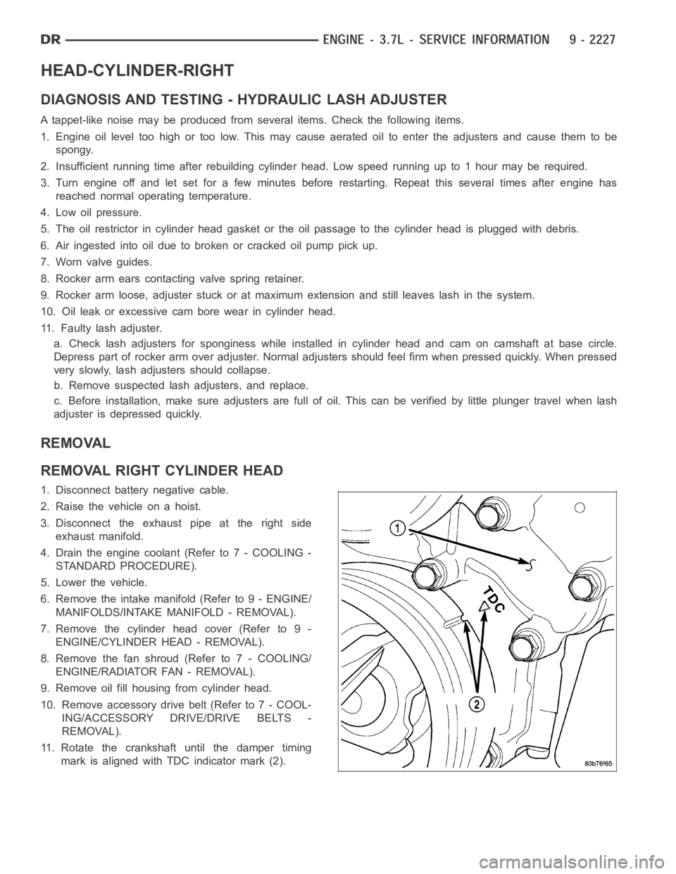
11. Rotate the crankshaft until the damper timing
mark is aligned with TDC indicator mark (2).
Page 1540 of 5267
2. Position the new cylinder head gasket on the locat-
ing dowels.
CAUTION: When installing cylinder head, use care
not damage the tensioner arm or the guide arm.
3. Position the cylinder head onto the cylinder block.
Make sure the cylinder head seats fully over the
locating dowels.
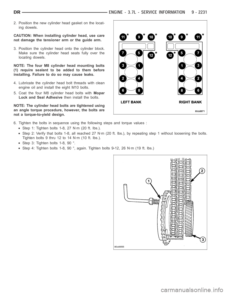
NOTE: The four M8 cylinder head mounting bolts
(1) require sealant to be added to them before
installing. Failure to do so may cause leaks.
4. Lubricate the cylinder head bolt threads with clean
engine oil and install the eight M10 bolts.
5. Coat the four M8 cylinder head bolts withMopar
Lock and Seal Adhesivethen install the bolts.
NOTE: The cylinder head bolts are tightened using
an angle torque procedure, however, the bolts are
not a torque-to-yield design.
6. Tighten the bolts in sequence using the following steps and torque values:
Step 1: Tighten bolts 1-8, 27 Nꞏm (20 ft. lbs.).
Step 2: Verify that bolts 1-8, all reached 27 Nꞏm (20 ft. lbs.), by repeatingstep 1 without loosening the bolts.
Tightenbolts9thru12to14Nꞏm(10ft.lbs.).
Step 3: Tighten bolts 1-8, 90 °.
Step 4: Tighten bolts 1-8, 90 °, again. Tighten bolts 9-12, 26 Nꞏm (19 ft. lbs.)
Page 1541 of 5267
CAUTION: The nut on the right side camshaft sprocket should not be removed for any reason, as the
sprocket and camshaft sensor target wheel is serviced as an assembly. If the nut was removed, torque nut
to 5 NM ( 60 in. lbs.).
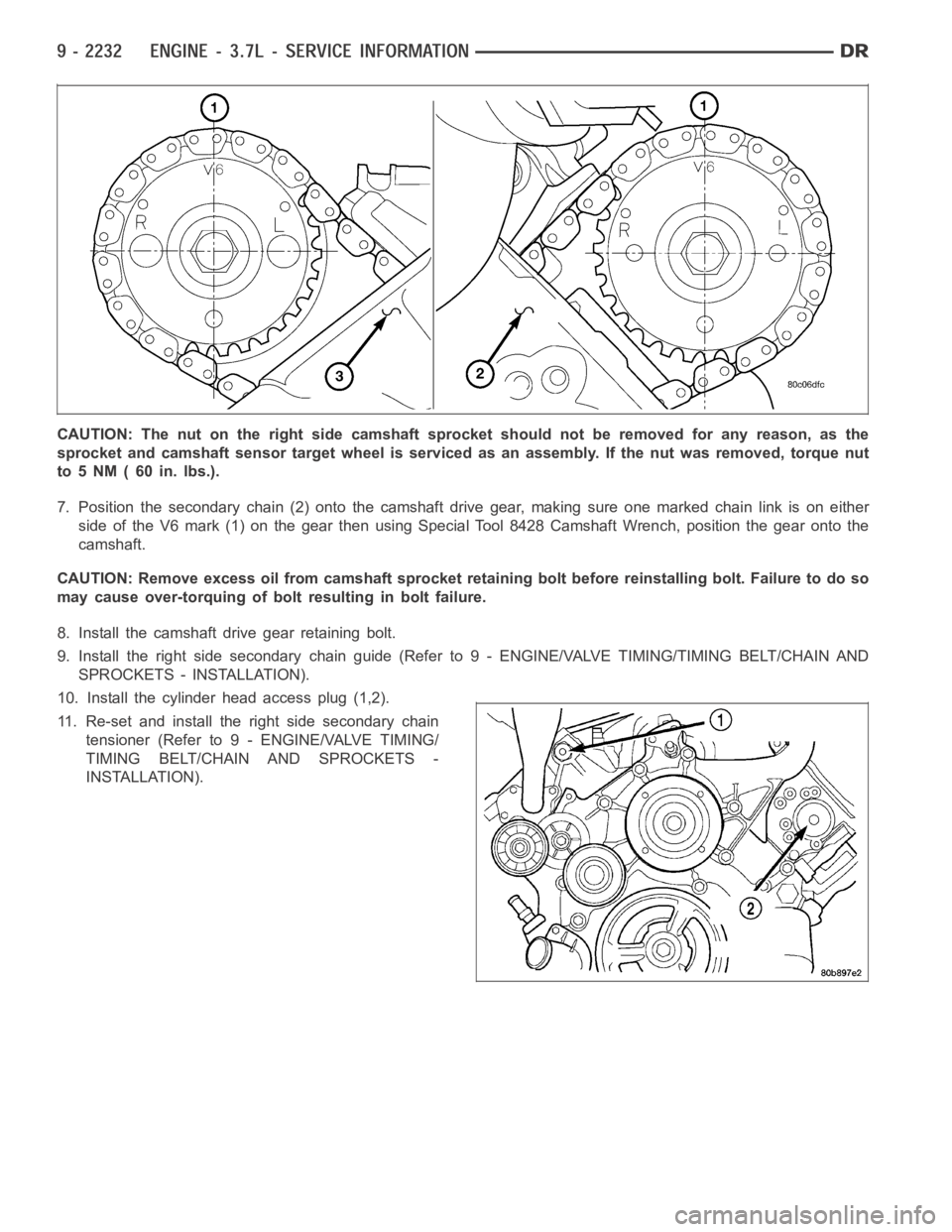
7. Position the secondary chain (2) onto the camshaft drive gear, making sure one marked chain link is on either
side of the V6 mark (1) on the gear then using Special Tool 8428 Camshaft Wrench, position the gear onto the
camshaft.
CAUTION: Remove excess oil from camshaft sprocket retaining bolt before reinstalling bolt. Failure to do so
may cause over-torquing of bolt resulting in bolt failure.
8. Install the camshaft drive gear retaining bolt.
9. Install the right side secondary chain guide (Refer to 9 - ENGINE/VALVE TIMING/TIMING BELT/CHAIN AND
SPROCKETS - INSTALLATION).
10. Install the cylinder head access plug (1,2).
11. Re-set and install the right side secondary chain
tensioner (Refer to 9 - ENGINE/VALVE TIMING/
TIMING BELT/CHAIN AND SPROCKETS -
INSTALLATION).
Page 1542 of 5267
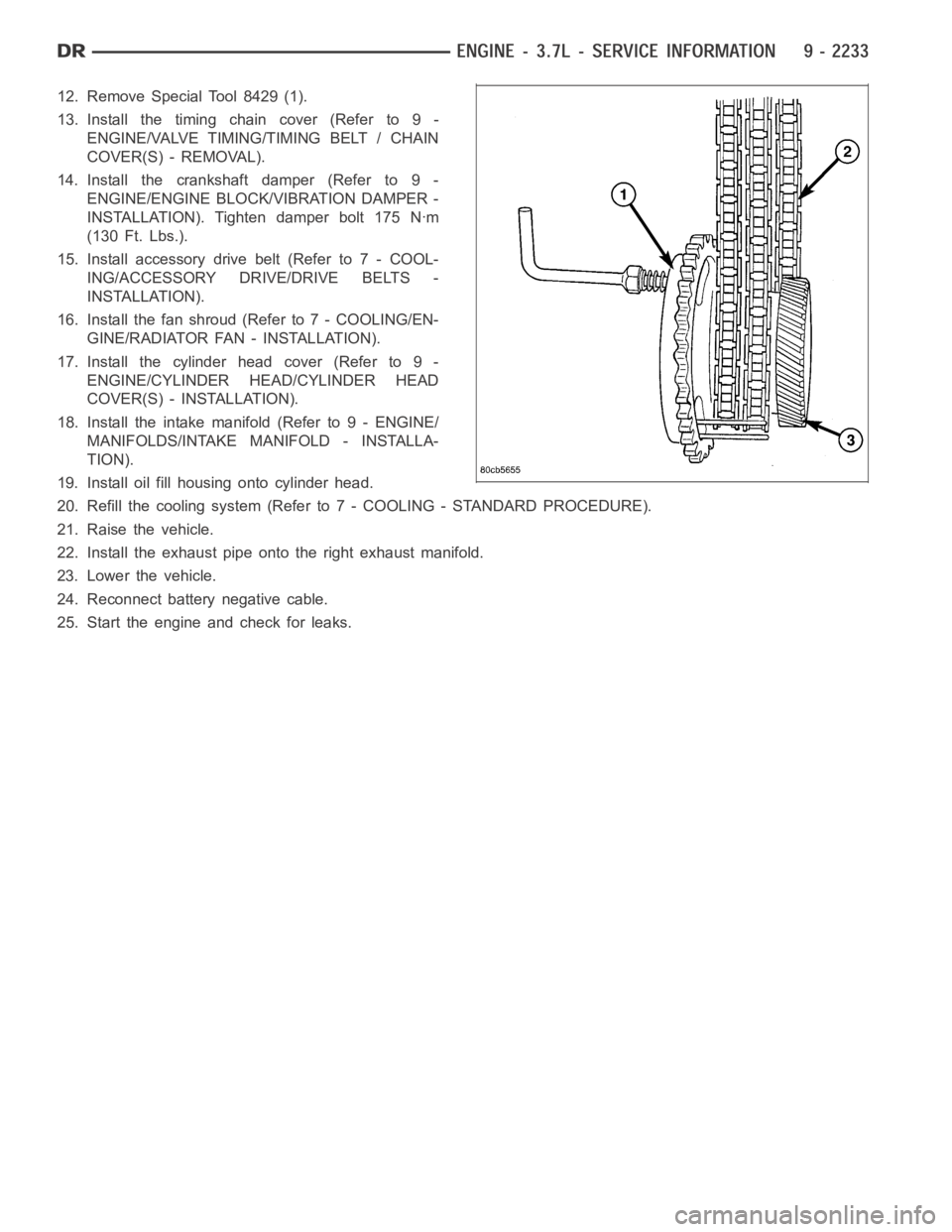
12. Remove Special Tool 8429 (1).
13. Install the timing chain cover (Refer to 9 -
ENGINE/VALVE TIMING/TIMING BELT / CHAIN
COVER(S) - REMOVAL).
14. Install the crankshaft damper (Refer to 9 -
ENGINE/ENGINE BLOCK/VIBRATION DAMPER -
INSTALLATION). Tighten damper bolt 175 Nꞏm
(130 Ft. Lbs.).
15. Install accessory drive belt (Refer to 7 - COOL-
ING/ACCESSORY DRIVE/DRIVE BELTS -
INSTALLATION).
16. Install the fan shroud (Refer to 7 - COOLING/EN-
GINE/RADIATOR FAN - INSTALLATION).
17. Install the cylinder head cover (Refer to 9 -
ENGINE/CYLINDER HEAD/CYLINDER HEAD
COVER(S) - INSTALLATION).
18. Install the intake manifold (Refer to 9 - ENGINE/
MANIFOLDS/INTAKE MANIFOLD - INSTALLA-
TION).
19. Install oil fill housing onto cylinder head.
20. Refill the cooling system (Refer to 7 - COOLING - STANDARD PROCEDURE).
21. Raise the vehicle.
22. Install the exhaust pipe onto the right exhaust manifold.
23. Lower the vehicle.
24. Reconnect battery negative cable.
25. Start the engine and check for leaks.
Page 1546 of 5267
INSTALLATION
1. Lubricate camshaft journals with clean engine oil.
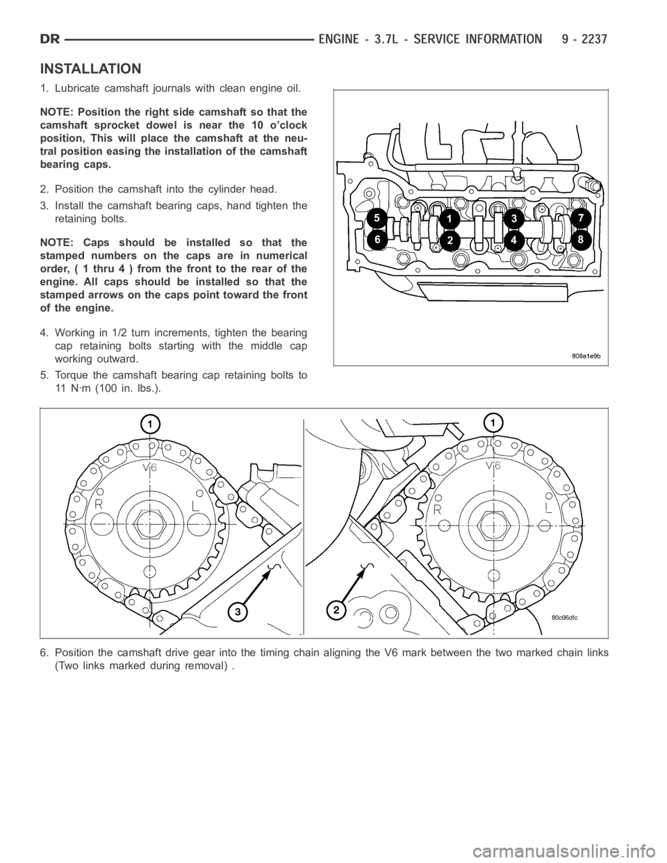
NOTE: Position the right side camshaft so that the
camshaft sprocket dowel is near the 10 o’clock
position, This will place the camshaft at the neu-
tral position easing the installation of the camshaft
bearing caps.
2. Position the camshaft into the cylinder head.
3. Install the camshaft bearing caps, hand tighten the
retaining bolts.
NOTE: Caps should be installed so that the
stamped numbers on the caps are in numerical
order, ( 1 thru 4 ) from the front to the rear of the
engine. All caps should be installed so that the
stamped arrows on the caps point toward the front
of the engine.
4. Working in 1/2 turn increments, tighten the bearing
cap retaining bolts starting with the middle cap
working outward.
5. Torque the camshaft bearing cap retaining bolts to
11 N ꞏm ( 1 0 0 i n . l b s . ) .
6. Position the camshaft drive gear into the timing chain aligning the V6 mark between the two marked chain links
(Two links marked during removal) .
Page 1547 of 5267
7. Using Special Tool 8428 Camshaft Wrench (2),
rotate the camshaft until the camshaft sprocket
dowel is aligned with the slot in the camshaft
sprocket. Install the sprocket onto the camshaft.
CAUTION: Remove excess oil from camshaft
sprocket bolt. Failure to do so can cause bolt
over-torque resulting in bolt failure.
8. Remove excess oil from camshaft sprocket bolt,
then install the camshaft sprocket retaining bolt and
hand tighten.
9. Remove timing chain wedge special tool 8379 (1).
10. Using Special Tool 6958 spanner wrench with
adapter pins 8346, torque the camshaft sprocket
retaining bolt to 122 Nꞏm (90 ft. lbs.).
11. Install the camshaft position sensor.
12. Install the cylinder head cover (Refer to 9 -
ENGINE/CYLINDER HEAD/CYLINDER HEAD
COVER(S) - INSTALLATION).
Page 1548 of 5267
COVER - CYLINDER HEAD
REMOVAL
1. Disconnect battery negative cable.
2. Remove air cleaner assembly, resonator assembly and air inlet hose.
3. Drain cooling system, below the level of the heater hoses (Refer to 7 - COOLING - STANDARD PROCEDURE).
4. Remove accessory drive belt (Refer to 7 - COOLING/ACCESSORY DRIVE/DRIVE BELTS - REMOVAL).
5. Remove air conditioning compressor retaining bolts and move compressortotheleft.
6. Remove heater hoses.
7. Disconnect injector and ignition coil connectors.
8. Disconnect and remove positive crankcase ventilation (PCV) hose.
9. Remove oil fill tube.
10. Un-clip injector and ignition coil harness and move away from cylinderhead cover.
11. Remove right rear breather tube and filter assembly.
12. Remove cylinder head cover retaining bolts.
13. Remove cylinder head cover.
INSTALLATION
CAUTION: Do not use harsh cleaners to clean the cylinder head covers. Severedamagetocoversmay
occur.
NOTE: The gasket may be used again, provided no cuts, tears, or deformationhas occurred.
1. Clean cylinder head cover and both sealing surfaces. Inspect and replace gasket as necessary.
2. Tighten cylinder head cover bolts and double ended studs to 12 Nꞏm (105 in.lbs).
3. Install right rear breather tube and filter assembly.
4. Connect injector, ignition coil electrical connectors and harness retaining clips.
5. Install the oil fill tube.
6. Install PCV hose.
7. Install heater hoses.
8. Install air conditioning compressor retaining bolts.
9. Install accessory drive belt (Refer to 7 - COOLING/ACCESSORY DRIVE/DRIVE BELTS - INSTALLATION).
10. Fill Cooling system (Refer to 7 - COOLING - STANDARD PROCEDURE).
11. Install air cleaner assembly, resonator assembly and air inlet hose.
12. Connect battery negative cable.