Page 2360 of 5267
13. Connect Fuel Control Actuator (FCA) electrical
connector (3) to rear of injection pump.
14. Install intake manifold air intake tube (above injec-
tion pump). Tighten clamps.
15. Install accessory drive belt.
16. Connect both negative battery cables to both bat-
teries.
17. Check system for fuel or engine oil leaks.
Page 2361 of 5267
SENSOR - FUEL LEVEL SENDING UNIT
DESCRIPTION
The fuel gauge sending unit (fuel level sensor) is attached to the side of the fuel pump module. The sending unit
consists of a float, an arm, and a variable resistor track (card). The fuel transfer (lift) pump is also attached to the
fuel pump module.
OPERATION
For Fuel Gauge Operation:A constant input voltage source of about 12 volts (battery voltage) is supplied to the
resistor track on the fuel gauge sending unit. This is fed directly from theEngine Control Module (ECM).NOTE: For
diagnostic purposes, this 12V power source can only be verified with the circuit opened (fuel tank module
electrical connector unplugged). With the connectors plugged, output voltages will vary from about .6 volts
at FULL, to about 7.0 volts at EMPTY.The resistor track is used to vary the voltage (resistance) depending on fuel
tank float level. As fuel level increases, the float and arm move up, which decreases voltage. As fuel level
decreases, the float and arm move down, which increases voltage. The varied voltage signal is returned back to the
ECM through the sensor return circuit.
Both of the electrical circuits between the fuel gauge sending unit and theECM are hard-wired (not multi-plexed).
After the voltage signal is sent from the resistor track, and back to the ECM, the ECM will interpret the resistance
(voltage) data and send a message across the multi-plex bus circuits to theinstrument panel cluster. Here it is
translated into the appropriate fuel gauge level reading. Refer to Instrument Panel for additional information.
REMOVAL
REMOVAL/INSTALLATION
For diesel removal and installation procedures, refer to the gas section of Fuel System/Fuel Delivery. See Fuel
Level Sending Unit/Sensor Removal/Installation.
Page 2362 of 5267
LINES - FUEL
DESCRIPTION
Low-Pressure Lines Are:
the fuel supply line from fuel tank to fuel filter housing.
the fuel return line back to fuel tank.
the fuel drain (manifold) line at rear of cylinder head.
the fuel supply line from fuel filter to fuel injection pump.
the fuel injection pump return line.
High-Pressure Lines Are:
the fuel line from fuel injection pump to fuel rail.
the 6 fuel lines from fuel rail up to injector connector tubes
WARNING: High-pressure fuel lines deliver diesel fuel under extreme pressure from the injection pump to
the fuel injectors. This may be as high as 160,000 kpa (23,206 psi). Use extreme caution when inspecting for
high-pressure fuel leaks. Inspect for high-pressure fuel leaks with a sheet of cardboard. High fuel injection
pressure can cause personal injury if contact is made with the skin.
OPERATION
High-Pressure Lines
CAUTION: The high-pressure fuel lines must be held securely in the brace. The lines cannot contact each
other or other components. Do not attempt to weld high-pressure fuel linesor to repair lines that are dam-
aged. If lines are ever kinked or bent, they must be replaced. Use only the recommended lines when
replacement of high-pressure fuel line is necessary.
High-pressure fuel lines deliver fuel (under pressure) of up to approximately 160,000 kPa (23,206 PSI) from the
injection pump to the fuel injectors. The lines expand and contract from the high-pressure fuel pulses generated
during the injection process. All high-pressure fuel lines are of the samelength and inside diameter. Correct high-
pressure fuel line usage and installation is critical to smooth engine operation.
WARNING: Use extreme caution when inspecting for high-pressure fuel leaks. Inspect for high-pressure fuel
leaks with a sheet of cardboard. High fuel injection pressure can cause personal injury if contact is made
with the skin.
DIAGNOSIS AND TESTING
HIGH-PRESSURE FUEL LINE LEAKS
High-pressure fuel line leaks can cause starting problems and poor engineperformance.
WARNING: Due to extreme fuel pressures of up to 160,000 kpa (23,206 psi), use extreme caution when
inspecting for high-pressure fuel leaks. Do not get your hand or a finger near a suspected leak. Inspect for
high-pressure fuel leaks with a sheet of cardboard. High fuel injection pressure can cause personal injury if
contact is made with the skin.
Start the engine. Move the cardboard over the suspected high-pressure fuel line leak, and check for fuel spray onto
the cardboard. If line is leaking, retorque line while engine is shutdown.Replace damaged, restricted or leaking
high-pressure fuel lines with the correct replacement line.
CAUTION: The high-pressure fuel lines must be clamped securely in place inthe brace. The lines cannot
contact each other or other components. Do not attempt to weld high-pressure fuel lines or to repair lines
that are damaged. Only use the recommended lines when replacement of high-pressure fuel line is neces-
sary.
Page 2363 of 5267
REMOVAL
CAUTION: Cleanliness cannot be overemphasized when handling or replacingdieselfuelsystemcompo-
nents. This especially includes the fuel injectors, high-pressure fuel lines and fuel injection pump. Very tight
tolerances are used with these parts. Dirt contamination could cause rapid part wear and possible plugging
of fuel injector nozzle tip holes. This in turn could lead to possible engine misfire. Always wash/clean any
fuel system component thoroughly before disassembly and then air dry. Capor cover any open part after
disassembly. Before assembly, examine each part for dirt, grease or othercontaminants and clean if nec-
essary. When installing new parts, lubricate them with clean engine oil orclean diesel fuel only.
1. Disconnect both negative battery cables from both
batteries. Cover and isolate ends of cables.
2. Thoroughly clean fuel lines at both ends.
3. If removing fuel line at either No. 1 or No. 2 cylin-
der, the intake manifold air heater elements must
first be removed from top of intake manifold. Refer
to Intake Air Heater Removal / Installation for pro-
cedures.
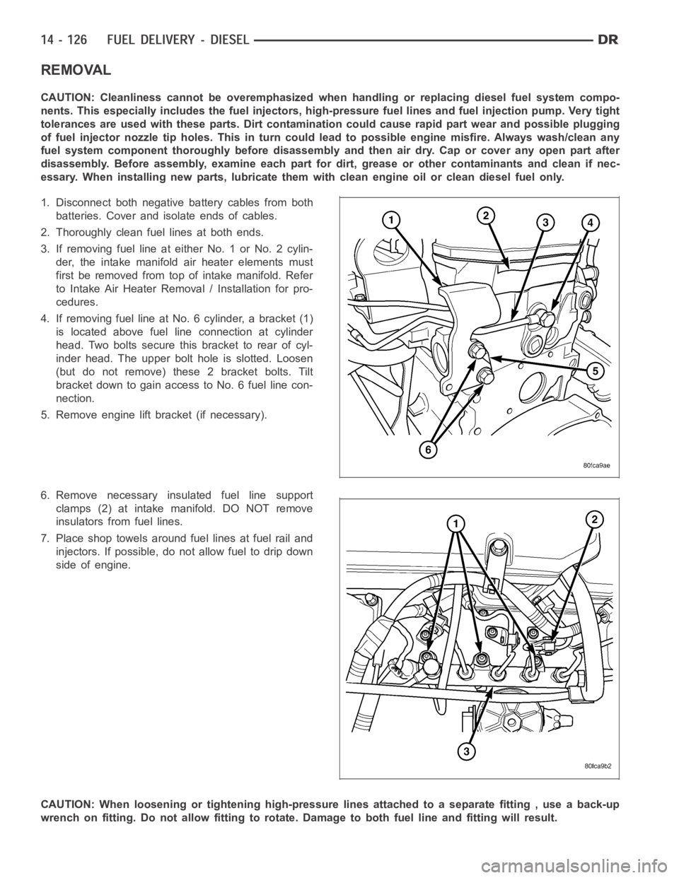
4. If removing fuel line at No. 6 cylinder, a bracket (1)
is located above fuel line connection at cylinder
head. Two bolts secure this bracket to rear of cyl-
inder head. The upper bolt hole is slotted. Loosen
(but do not remove) these 2 bracket bolts. Tilt
bracket down to gain access to No. 6 fuel line con-
nection.
5. Remove engine lift bracket (if necessary).
6. Remove necessary insulated fuel line support
clamps (2) at intake manifold. DO NOT remove
insulators from fuel lines.
7. Place shop towels around fuel lines at fuel rail and
injectors. If possible, do not allow fuel to drip down
side of engine.
CAUTION: When loosening or tightening high-pressure lines attached to a separate fitting , use a back-up
wrench on fitting. Do not allow fitting to rotate. Damage to both fuel line and fitting will result.
Page 2367 of 5267
VALVE - FUEL PRESSURE LIMITING
DESCRIPTION
The fuel pressure limiting valve is located on the top of the fuel rail.
OPERATION
Fuel pressure at the fuel rail is monitored by the fuel rail pressure sensor. If fuel pressure becomes excessive, the
pressure limiting valve opens and vents excess pressure into the fuel draincircuit.
REMOVAL
CAUTION: Cleanliness cannot be overemphasized when handling or replacingdieselfuelsystemcompo-
nents. This especially includes the fuel injectors, high-pressure fuel lines and fuel injection pump. Very tight
tolerances are used with these parts. Dirt contamination could cause rapid part wear and possible plugging
of fuel injector nozzle tip holes. This in turn could lead to possible engine misfire. Always wash/clean any
fuel system component thoroughly before disassembly and then air dry. Capor cover any open part after
disassembly. Before assembly, examine each part for dirt, grease or othercontaminants and clean if nec-
essary. When installing new parts, lubricate them with clean engine oil orclean diesel fuel only.
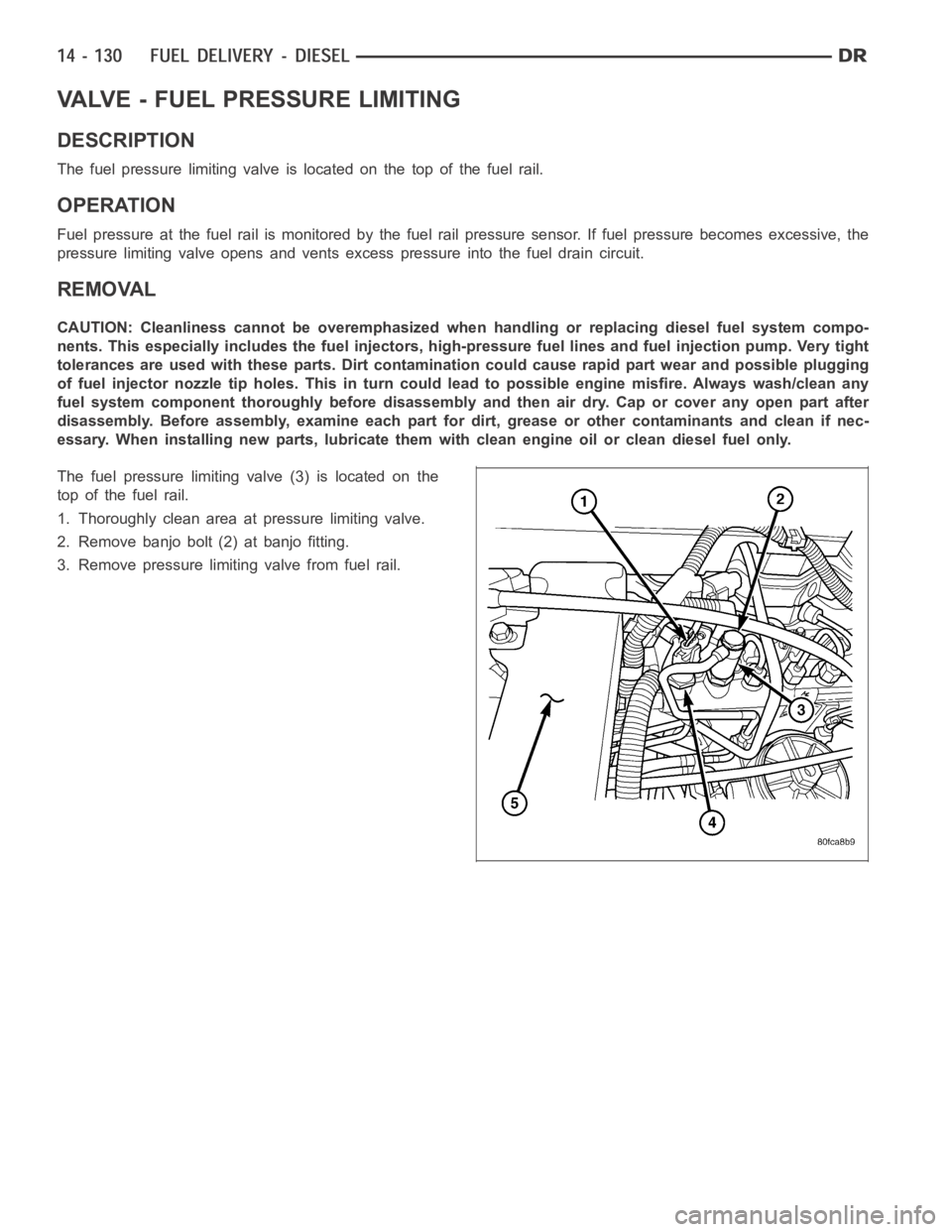
The fuel pressure limiting valve (3) is located on the
top of the fuel rail.
1. Thoroughly clean area at pressure limiting valve.
2. Remove banjo bolt (2) at banjo fitting.
3. Remove pressure limiting valve from fuel rail.
Page 2369 of 5267
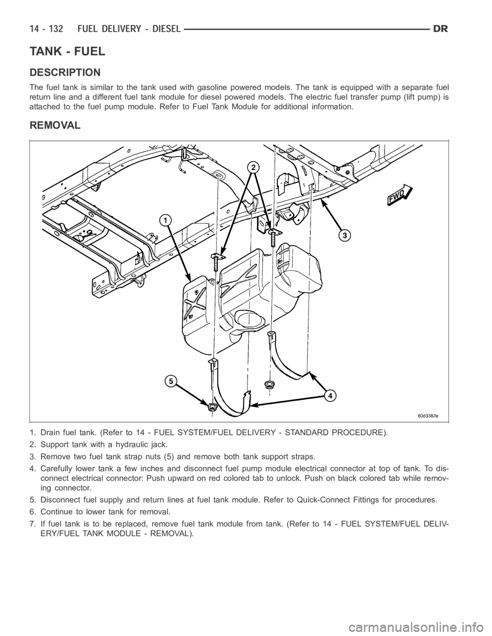
TA N K - F U E L
DESCRIPTION
The fuel tank is similar to the tank used with gasoline powered models. The tank is equipped with a separate fuel
return line and a different fuel tank module for diesel powered models. Theelectric fuel transfer pump (lift pump) is
attached to the fuel pump module. Refer to Fuel Tank Module for additional information.
REMOVAL
1. Drain fuel tank. (Refer to 14 - FUEL SYSTEM/FUEL DELIVERY - STANDARD PROCEDURE).
2. Support tank with a hydraulic jack.
3. Remove two fuel tank strap nuts (5) and remove both tank support straps.
4. Carefully lower tank a few inches and disconnect fuel pump module electrical connector at top of tank. To dis-
connect electrical connector: Push upward on red colored tab to unlock. Push on black colored tab while remov-
ing connector.
5. Disconnect fuel supply and return lines at fuel tank module. Refer to Quick-Connect Fittings for procedures.
6. Continue to lower tank for removal.
7. If fuel tank is to be replaced, remove fuel tank module from tank. (Refer to 14 - FUEL SYSTEM/FUEL DELIV-
ERY/FUEL TANK MODULE - REMOVAL).
Page 2371 of 5267
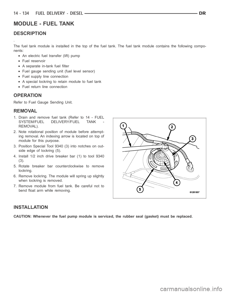
MODULE - FUEL TANK
DESCRIPTION
.
The fuel tank module is installed in the top of the fuel tank. The fuel tank module contains the following compo-
nents:
An electric fuel transfer (lift) pump
Fuel reservoir
A separate in-tank fuel filter
Fuel gauge sending unit (fuel level sensor)
Fuel supply line connection
A special lockring to retain module to fuel tank
Fuel return line connection
OPERATION
Refer to Fuel Gauge Sending Unit.
REMOVAL
1. Drain and remove fuel tank (Refer to 14 - FUEL
SYSTEM/FUEL DELIVERY/FUEL TANK -
REMOVAL).
2. Note rotational position of module before attempt-
ing removal. An indexing arrow is located on top of
module for this purpose.
3. Position Special Tool 9340 (3) into notches on out-
side edge of lockring (5).
4. Install 1/2 inch drive breaker bar (1) to tool 9340
(3).
5. Rotate breaker bar counterclockwise to remove
lockring.
6. Remove lockring. The module will spring up slightly
when lockring is removed.
7. Remove module from fuel tank. Be careful not to
bend float arm while removing.
INSTALLATION
CAUTION: Whenever the fuel pump module is serviced, the rubber seal (gasket) must be replaced.
Page 2372 of 5267
1. Using a new seal (gasket), position fuel pump mod-
uleintoopeninginfueltank.
2. Position lockring (5) over top of fuel pump module.
3. Rotate module until embossed alignment arrow
points to center alignment mark. This step must be
performed to prevent float from contacting side of
fuel tank. Also be sure fuel fitting on top of pump
module is pointed to drivers side of vehicle.
4. Install Special Tool 9340 (3) to lockring.
5. Install 1/2 inch drive breaker (1) into Special Tool
9340 (3).
6. Tighten lockring (clockwise) until all seven notches
have engaged.
7. Install fuel tank (Refer to 14 - FUEL SYSTEM/
FUEL DELIVERY/FUEL TANK - INSTALLATION).