2006 DODGE RAM SRT-10 fuel pump
[x] Cancel search: fuel pumpPage 5203 of 5267
page page
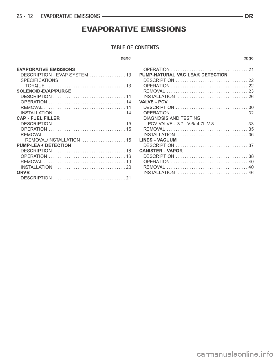
EVAPORATIVE EMISSIONS
DESCRIPTION - EVAP SYSTEM ................ 13
SPECIFICATIONS
TORQUE ................................... 13
SOLENOID-EVAP/PURGE
DESCRIPTION ................................ 14
OPERATION .................................. 14
REMOVAL .................................... 14
INSTALLATION ............................... 14
CAP - FUEL FILLER
DESCRIPTION ................................ 15
OPERATION .................................. 15
REMOVAL
REMOVAL/INSTALLATION ................... 15
PUMP-LEAK DETECTION
DESCRIPTION ................................ 16
OPERATION .................................. 16
REMOVAL .................................... 19
INSTALLATION ............................... 20
ORVR
DESCRIPTION ................................ 21OPERATION .................................. 21
PUMP-NATURAL VAC LEAK DETECTION
DESCRIPTION ................................ 22
OPERATION .................................. 22
REMOVAL .................................... 23
INSTALLATION ............................... 26
VA LV E - P C V
DESCRIPTION ................................ 30
OPERATION .................................. 32
DIAGNOSIS AND TESTING
PCV VALVE - 3.7L V-6/ 4.7L V-8 .............. 33
REMOVAL .................................... 35
INSTALLATION ............................... 36
LINES - VACUUM
DESCRIPTION ................................ 37
CANISTER - VAPOR
DESCRIPTION ................................ 38
OPERATION .................................. 40
REMOVAL .................................... 40
INSTALLATION ............................... 46
Page 5204 of 5267
EVAPORATIVE EMISSIONS
DESCRIPTION - EVAP SYSTEM
The evaporation control system prevents the emission of fuel tank vapors into the atmosphere. When fuel evapo-
rates in the fuel tank, the vapors pass through vent hoses or tubes into the two charcoal filled evaporative canisters.
The canisters temporarily hold the vapors. The Powertrain Control Module(PCM) allows intake manifold vacuum to
draw vapors into the combustion chambers during certain operating conditions.
All gasoline powered engines use a duty cycle purge system. The PCM controls vapor flow by operating the duty
cycle EVAP purge solenoid. Refer to Duty Cycle EVAP Canister Purge Solenoid for additional information.
When equipped with certain emissions packages, a Leak Detection Pump (LDP) will be used as part of the evap-
orative system. This pump is used as a part of OBD II requirements. Refer to Leak Detection Pump for additional
information. Other emissions packages will use a Natural Vacuum Leak Detection (NVLD) system in place of the
LDP. Refer to NVLD for additional information.
NOTE: The hoses used in this system are specially manufactured. If replacement becomes necessary, it is
important to use only fuel resistant hose.
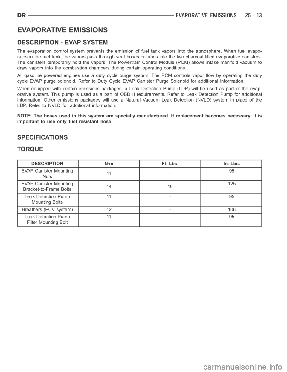
SPECIFICATIONS
TORQUE
DESCRIPTION Nꞏm Ft. Lbs. In. Lbs.
EVAP Canister Mounting
Nuts11 -95
EVAP Canister Mounting
Bracket-to-Frame Bolts14 10125
Leak Detection Pump
Mounting Bolts11 - 9 5
Breathers (PCV system) 12 - 106
Leak Detection Pump
Filter Mounting Bolt11 - 9 5
Page 5206 of 5267
CAP - FUEL FILLER
DESCRIPTION
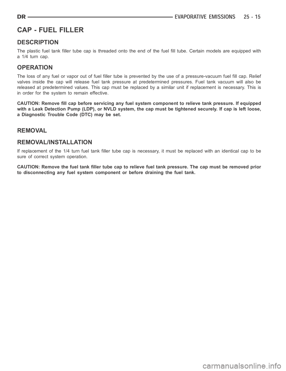
The plastic fuel tank filler tube cap isthreaded onto the end of the fuel fill tube. Certain models are equipped with
a 1/4 turn cap.
OPERATION
The loss of any fuel or vapor out of fuel filler tube is prevented by the use ofa pressure-vacuum fuel fill cap. Relief
valves inside the cap will release fuel tank pressure at predetermined pressures. Fuel tank vacuum will also be
released at predetermined values. This cap must be replaced by a similar unit if replacement is necessary. This is
in order for the system to remain effective.
CAUTION: Remove fill cap before servicing any fuel system component to relieve tank pressure. If equipped
with a Leak Detection Pump (LDP), or NVLD system, the cap must be tightened securely. If cap is left loose,
a Diagnostic Trouble Code (DTC) may be set.
REMOVAL
REMOVAL/INSTALLATION
If replacement of the 1/4 turn fuel tank filler tube cap is necessary, it mustbereplacedwithanidenticalcaptobe
sure of correct system operation.
CAUTION: Remove the fuel tank filler tube cap to relieve fuel tank pressure. The cap must be removed prior
to disconnecting any fuel system component or before draining the fuel tank.
Page 5207 of 5267
PUMP-LEAK DETECTION
DESCRIPTION
Vehicles equipped with JTEC engine control modules use a leak detection pump. Vehicles equipped with NGC
engine control modules use an NVLD pump. Refer to Natural Vacuum - Leak Detection (NVLD) for additional infor-
mation.
The evaporative emission system is designed to prevent the escape of fuel vapors from the fuel system. Leaks in
the system, even small ones, can allow fuel vapors to escape into the atmosphere. Government regulations require
onboard testing to make sure that the evaporative (EVAP) system is functioning properly. The leak detection system
tests for EVAP system leaks and blockage. It also performs self-diagnostics. During self-diagnostics, the Powertrain
Control Module (PCM) first checks the Leak Detection Pump (LDP) for electrical and mechanical faults. If the first
checks pass, the PCM then uses the LDP to seal the vent valve and pump air intothe system to pressurize it. If a
leak is present, the PCM will continue pumping the LDP to replace the air that leaks out. The PCM determines the
size of the leak based on how fast/long it must pump the LDP as it tries to maintain pressure in the system.
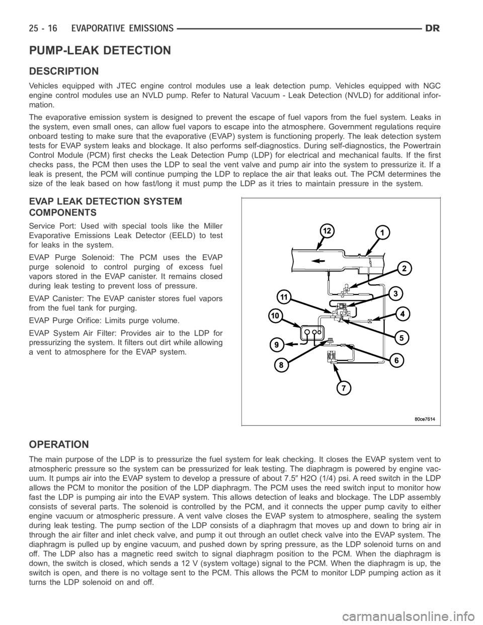
EVAP LEAK DETECTION SYSTEM
COMPONENTS
Service Port: Used with special tools like the Miller
Evaporative Emissions Leak Detector (EELD) to test
for leaks in the system.
EVAP Purge Solenoid: The PCM uses the EVAP
purge solenoid to control purging of excess fuel
vapors stored in the EVAP canister. It remains closed
during leak testing to prevent loss of pressure.
EVAP Canister: The EVAP canister stores fuel vapors
from the fuel tank for purging.
EVAP Purge Orifice: Limits purge volume.
EVAP System Air Filter: Provides air to the LDP for
pressurizing the system. It filters out dirt while allowing
a vent to atmosphere for the EVAP system.
OPERATION
The main purpose of the LDP is to pressurize the fuel system for leak checking. It closes the EVAP system vent to
atmospheric pressure so the system can be pressurized for leak testing. The diaphragm is powered by engine vac-
uum. It pumps air into the EVAP system to develop a pressure of about 7.5
H2O (1/4) psi. A reed switch in the LDP
allows the PCM to monitor the position of the LDP diaphragm. The PCM uses thereed switch input to monitor how
fast the LDP is pumping air into the EVAP system. This allows detection of leaks and blockage. The LDP assembly
consists of several parts. The solenoid is controlled by the PCM, and it connects the upper pump cavity to either
engine vacuum or atmospheric pressure. A vent valve closes the EVAP systemto atmosphere, sealing the system
during leak testing. The pump section of the LDP consists of a diaphragm that moves up and down to bring air in
through the air filter and inlet check valve, and pump it out through an outlet check valve into the EVAP system. The
diaphragm is pulled up by engine vacuum, and pushed down by spring pressure, as the LDP solenoid turns on and
off. The LDP also has a magnetic reed switch to signal diaphragm position tothe PCM. When the diaphragm is
down, the switch is closed, which sends a 12 V (system voltage) signal to thePCM. When the diaphragm is up, the
switch is open, and there is no voltage sent to the PCM. This allows the PCM tomonitor LDP pumping action as it
turns the LDP solenoid on and off.
Page 5210 of 5267
REMOVAL
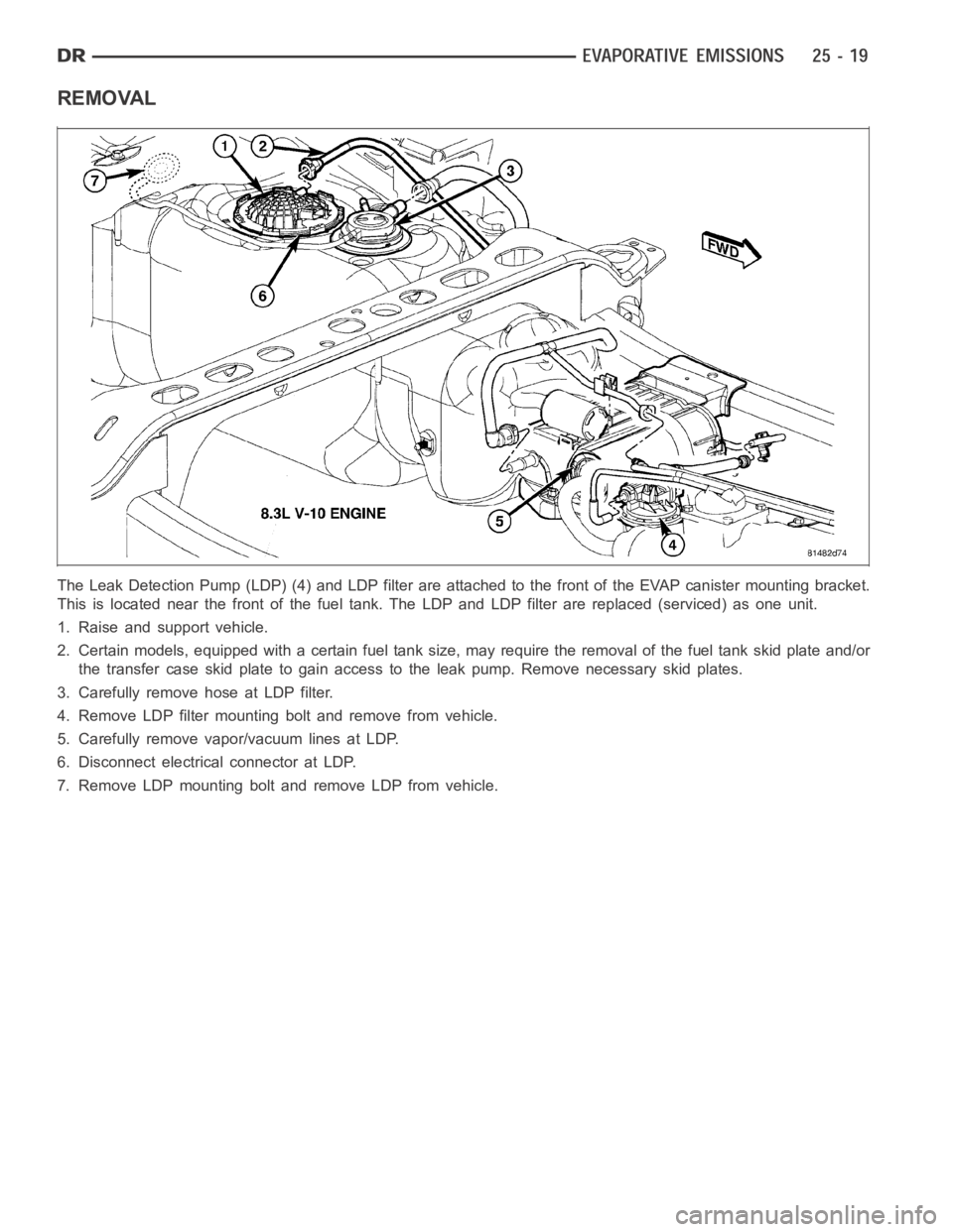
The Leak Detection Pump (LDP) (4) and LDP filter are attached to the front ofthe EVAP canister mounting bracket.
This is located near the front of the fuel tank. The LDP and LDP filter are replaced (serviced) as one unit.
1. Raise and support vehicle.
2. Certain models, equipped with a certain fuel tank size, may require the removal of the fuel tank skid plate and/or
the transfer case skid plate to gain access to the leak pump. Remove necessary skid plates.
3. Carefully remove hose at LDP filter.
4. Remove LDP filter mounting bolt and remove from vehicle.
5. Carefully remove vapor/vacuum lines at LDP.
6. Disconnect electrical connector at LDP.
7. Remove LDP mounting bolt and remove LDP from vehicle.
Page 5213 of 5267
PUMP-NATURAL VAC LEAK DETECTION
DESCRIPTION
Vehicles equipped with an NGC Powertrain Control Module (PCM) use a Natural Vacuum Leak Detection (NVLD)
pump and system. Vehicles equipped with a JTEC PCM use an LDP (Leak Detection Pump). Refer to Leak Detec-
tion Pump (LDP) for additional information.
The NVLD pump is located in the same area as the leak detection pump. Refer toNVLD Removal / Installation for
additional information.
OPERATION
The Natural Vacuum Leak Detection (NVLD) system is the next generation evaporative leak detection system that
will first be used on vehicles equipped with the Next Generation Controller (NGC). This new system replaces the
leak detection pump as the method of evaporative system leak detection. This is to detect a leak equivalent to a
0.020
(0.5 mm) hole. This system has the capability to detect holes of this size very dependably.
The basic leak detection theory employed with NVLD is the
Gas Law. This is to say that the pressure in a sealed
vessel will change if the temperature of the gas in the vessel changes. The vessel will only see this effect if it is
indeed sealed. Even small leaks will allow the pressure in the vessel to come to equilibrium with the ambient pres-
sure. In addition to the detection of very small leaks, this system has the capability of detecting medium as well as
large evaporative system leaks.
A vent valve seals the canister vent during engine off conditions. If the vapor system has a leak of less than the
failure threshold, the evaporativesystem will be pulled into a vacuum, either due to the cool down from operating
temperature or diurnal ambient temperature cycling. The diurnal effect is considered one of the primary contributors
to the leak determination by this diagnostic. When the vacuum in the systemexceeds about 1
H2O (0.25 KPA), a
vacuum switch closes. The switch closure sends a signal to the NGC. The NGC,via appropriate logic strategies,
utilizes the switch signal, or lack thereof, to make a determination of whether a leak is present.
The NVLD device is designed with a normally open vacuum switch, a normally closed solenoid, and a seal, which
is actuated by both the solenoid and a diaphragm. The NVLD is located on the atmospheric vent side of the can-
ister. The NVLD assembly may be mounted on top of the canister outlet, or in-line between the canister and atmo-
spheric vent filter. The normally open vacuum switch will close with about1
H2O (0.25 KPA) vacuum in the
evaporative system. The diaphragm actuates the switch. This is above the opening point of the fuel inlet check valve
in the fill tube so cap off leaks can be detected. Submerged fill systems must have recirculation lines that do not
have the in-line normally closed check valve that protects the system fromfailednozzleliquidingestion,inorderto
detect cap off conditions.
The normally closed valve in the NVLD is intended to maintain the seal on theevaporative system during the engine
off condition. If vacuum in the evaporative system exceeds 3
to 6H2O (0.75 to 1.5 KPA), the valve will be pulled
off the seat, opening the seal. This will protect the system from excessivevacuum as well as allowing sufficient
purge flow in the event that the solenoid was to become inoperative.
The solenoid actuates the valve to unseal the canister vent while the engine is running. It also will be used to close
the vent during the medium and large leak tests and during the purge flow check. This solenoid requires an initial
1.5 amps of current to pull the valveopen, but after 100 mili-seconds, willbedutycycleddowntoanaverageof
about 150 mA for the remainder of the drive cycle.
Another feature in the device is a diaphragm that will open the seal in the NVLD with pressure in the evaporative
system. The device will
blow offat about 0.5H2O (0.12 KPA) pressure to permit the venting of vapors during
refueling. An added benefit to this is that it will also allow the tank to
breatheduring increasing temperatures, thus
limiting the pressure in the tank to this low level. This is beneficial because the induced vacuum during a subse-
quent declining temperature will achieve the switch closed (pass threshold) sooner than if the tank had to decay
from a built up pressure.
The device itself has 3 wires: Switch sense, solenoid driver and ground. Italso includes a resistor to protect the
switch from a short to battery or a short to ground. The NGC utilizes a high-side driver to energize and duty-cycle
the solenoid.
Page 5214 of 5267
REMOVAL
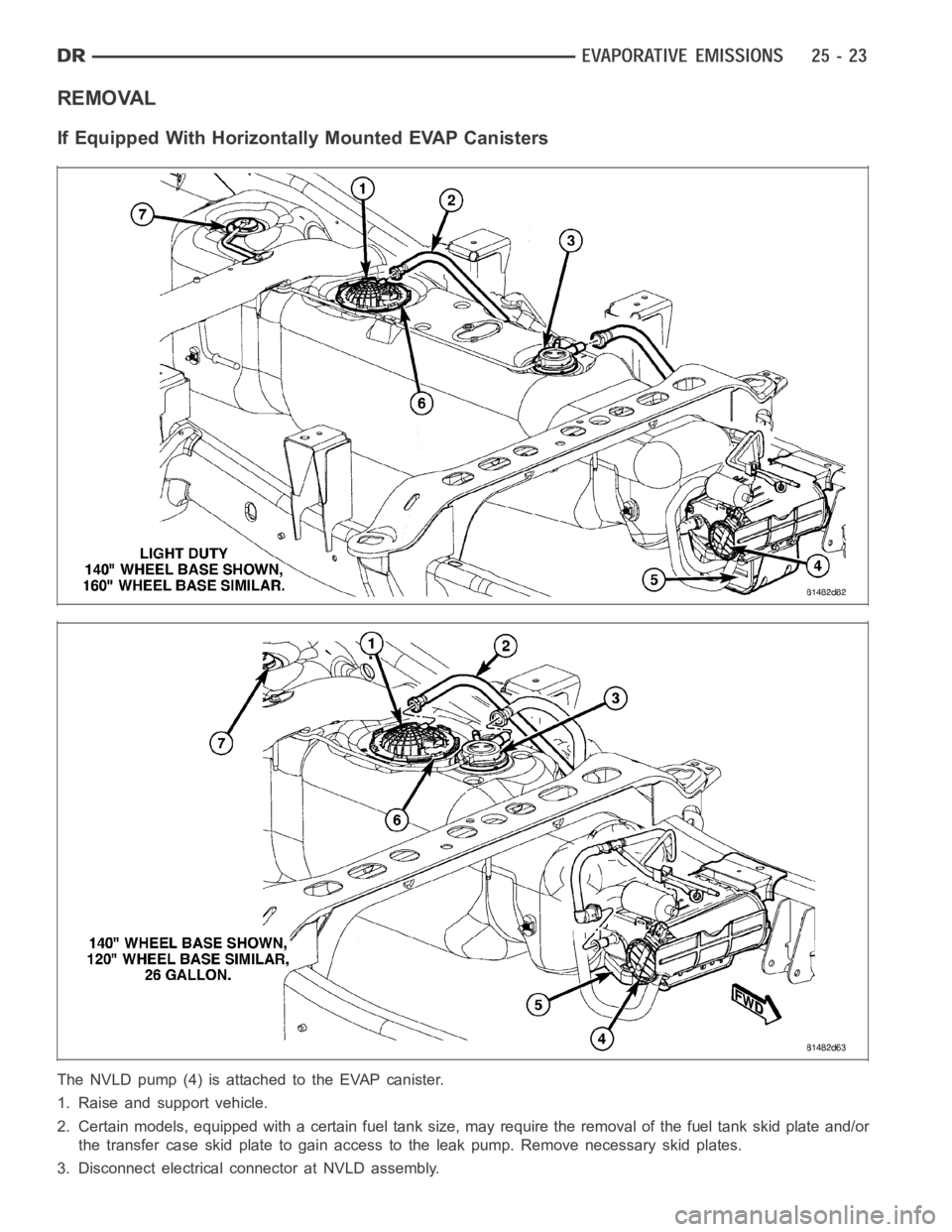
If Equipped With Horizontally Mounted EVAP Canisters
The NVLD pump (4) is attached to the EVAP canister.
1. Raise and support vehicle.
2. Certain models, equipped with a certain fuel tank size, may require the removal of the fuel tank skid plate and/or
the transfer case skid plate to gain access to the leak pump. Remove necessary skid plates.
3. Disconnect electrical connector at NVLD assembly.
Page 5216 of 5267
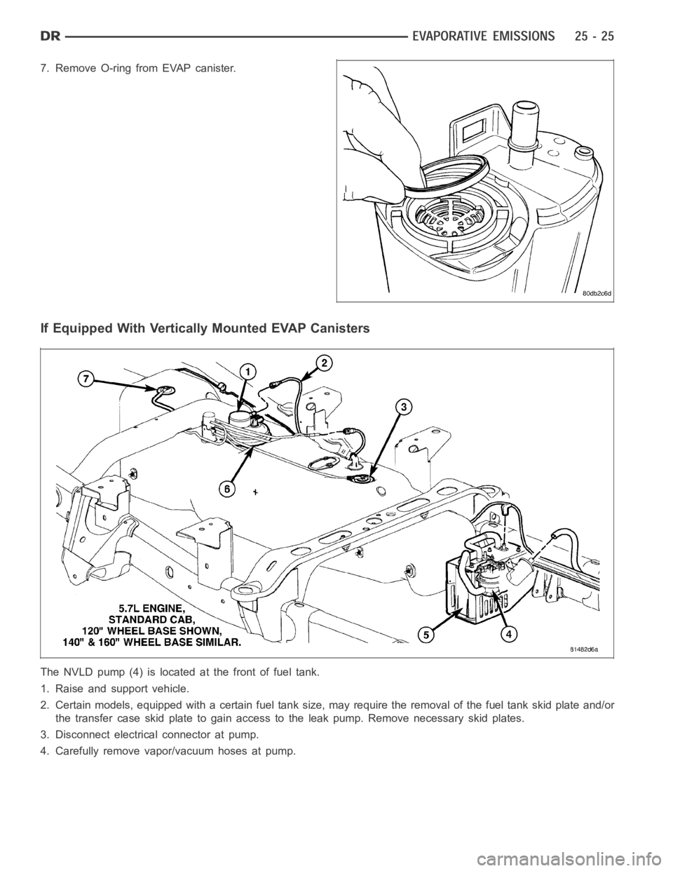
7. Remove O-ring from EVAP canister.
If Equipped With Vertically Mounted EVAP Canisters
The NVLD pump (4) is located at the front of fuel tank.
1. Raise and support vehicle.
2. Certain models, equipped with a certain fuel tank size, may require the removal of the fuel tank skid plate and/or
the transfer case skid plate to gain access to the leak pump. Remove necessary skid plates.
3. Disconnect electrical connector at pump.
4. Carefully remove vapor/vacuum hoses at pump.