Page 2283 of 5267

PEDAL - ACCELERATOR
REMOVAL
The following procedure applies only to vehicles with-
out the Adjustable Pedal Package (code XAP).
The accelerator pedal is serviced as a complete
assembly including the bracket.
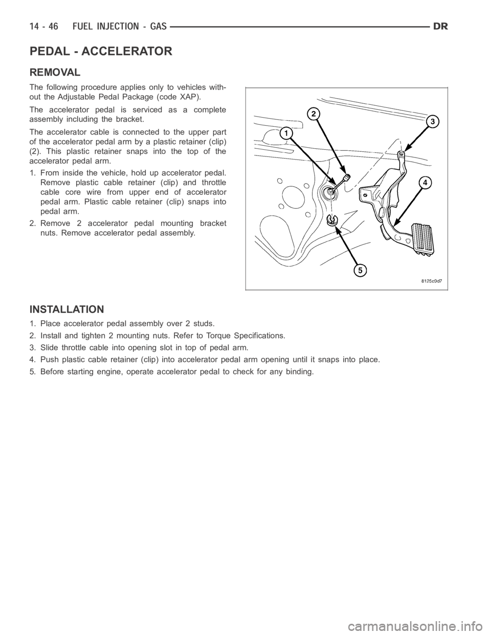
The accelerator cable is connected to the upper part
of the accelerator pedal arm by a plastic retainer (clip)
(2). This plastic retainer snaps into the top of the
accelerator pedal arm.
1. From inside the vehicle, hold up accelerator pedal.
Remove plastic cable retainer (clip) and throttle
cable core wire from upper end of accelerator
pedal arm. Plastic cable retainer (clip) snaps into
pedal arm.
2. Remove 2 accelerator pedal mounting bracket
nuts. Remove accelerator pedal assembly.
INSTALLATION
1. Place accelerator pedal assembly over 2 studs.
2. Install and tighten 2 mounting nuts. Refer to Torque Specifications.
3. Slide throttle cable into opening slot in top of pedal arm.
4. Push plastic cable retainer (clip) into accelerator pedal arm opening until it snaps into place.
5. Before starting engine, operate accelerator pedal to check for any binding.
Page 2284 of 5267
SENSOR-ACCELERATOR PEDAL POSITION
DESCRIPTION
The Accelerator Pedal Position Sensor (APPS) (1) is
located inside the vehicle.It is attached to the accel-
erator pedal assembly (3). It is used only on 5.7L V-8
gas engines and diesel engines.
OPERATION
The Accelerator Pedal Position Sensor (APPS) provides the Powertrain Control Module (PCM) with two DC voltage
signals which change as the position of the accelerator pedal changes. Oneof the DC voltage signals will be half
the voltage of the other signal.
REMOVAL
CAUTION: Do not attempt to separate or remove the Accelerator Pedal Position Sensor (APPS) from the
accelerator pedal assembly. The APPS is replaced as an assembly along withthe pedal. If sensor is
removed from pedal, its electronic calibration may be destroyed.
1. Disconnect 6–way electrical connector at top of
APPS (2).
2. Remove APPS lower mounting bolt (4) and two
mounting nuts.
3. Remove pedal and APPS assembly from vehicle.
Page 2287 of 5267
5.7L V-8
The Crankshaft Position (CKP) (4) sensor is mounted
into the right rear side of the cylinder block. It is posi-
tioned and bolted into a machined hole.
OPERATION
3.7L V-6
Engine speed and crankshaft position are provided
through the CKP (Crankshaft Position) sensor. The
sensor generates pulses that are the input sent to the
Powertrain Control Module (PCM). The PCM interprets
the sensor input to determine the crankshaft position.
The PCM then uses this position, along with other
inputs, to determine injector sequence and ignition
timing.
The sensor is a hall effect device combined with an
internal magnet. It is also sensitive to steel within a
certain distance from it.
A tonewheel (targetwheel) (1) is bolted to the engine
crankshaft. This tonewheel has sets of notches (2) at
its outer edge.
The notches cause a pulse to be generated when they
pass under the sensor. The pulses are the input to the
PCM.
Page 2288 of 5267

4.7L V-8
Engine speed and crankshaft position are provided
through the CKP (Crankshaft Position) sensor. The
sensor generates pulses that are the input sent to the
Powertrain Control Module (PCM). The PCM interprets
the sensor input to determine the crankshaft position.
The PCM then uses this position, along with other
inputs, to determine injector sequence and ignition
timing.
The sensor is a hall effect device combined with an
internal magnet. It is also sensitive to steel within a
certain distance from it.
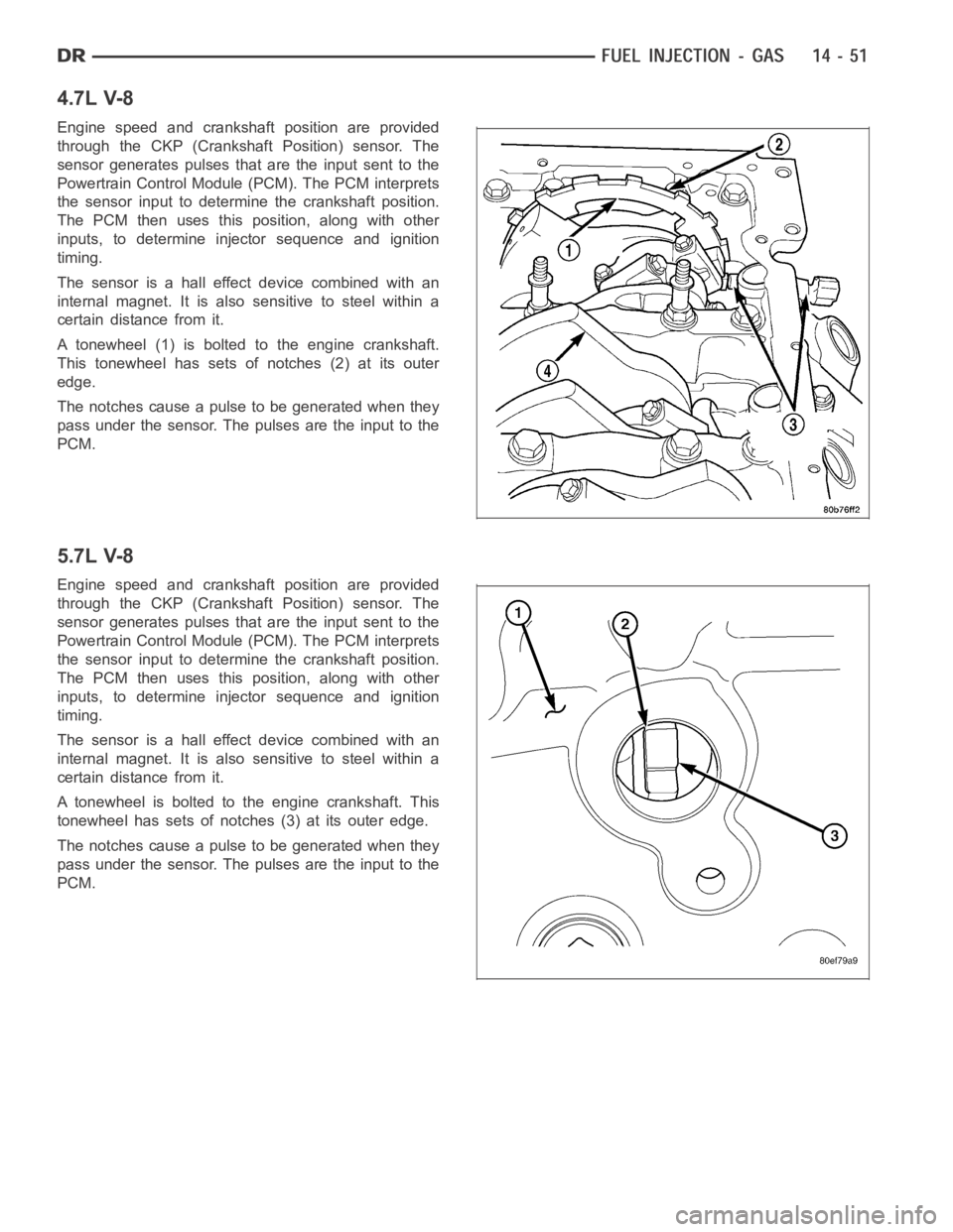
A tonewheel (1) is bolted to the engine crankshaft.
This tonewheel has sets of notches (2) at its outer
edge.
The notches cause a pulse to be generated when they
pass under the sensor. The pulses are the input to the
PCM.
5.7L V-8
Engine speed and crankshaft position are provided
through the CKP (Crankshaft Position) sensor. The
sensor generates pulses that are the input sent to the
Powertrain Control Module (PCM). The PCM interprets
the sensor input to determine the crankshaft position.
The PCM then uses this position, along with other
inputs, to determine injector sequence and ignition
timing.
The sensor is a hall effect device combined with an
internal magnet. It is also sensitive to steel within a
certain distance from it.
A tonewheel is bolted to the engine crankshaft. This
tonewheel has sets of notches (3) at its outer edge.
The notches cause a pulse to be generated when they
pass under the sensor. The pulses are the input to the
PCM.
Page 2289 of 5267
REMOVAL
3.7L V-6
The Crankshaft Position (CKP) sensor is mounted into
the right rear side of the cylinder block. It is positioned
and bolted into a machined hole.
1. Raise vehicle.
2. Disconnect sensor electrical connector.
3. Remove sensor mounting bolt (1).
4. Carefully twist sensor (2) from cylinder block.
5. Check condition of sensor O-ring (3).
4.7L V-8
The Crankshaft Position (CKP) sensor is located at
the right-rear side of the engine cylinder block. It is
positioned and bolted into a machined hole in the
engine block.
1. Raise vehicle.
2. Disconnect CKP electrical connector at sensor.
3. Remove CKP mounting bolt (2).
4. Carefully twist sensor (1) from cylinder block.
5. Remove sensor from vehicle.
6. Check condition of sensor O-ring.
Page 2290 of 5267
5.7L V-8
The Crankshaft Position (CKP) sensor (4) is located at
the right-rear side of the engine cylinder block. It is
positioned and bolted into a machined hole in the
engine block.
1. Raise vehicle.
2. Disconnect CKP electrical connector at sensor.
3. Remove CKP mounting bolt (3).
4. Carefully twist sensor (4) from cylinder block.
5. Remove sensor from vehicle.
6. Check condition of sensor O-ring.
8.3L - SRT-10
The sensor is located at the rear lower passenger side
of motor.
Page 2291 of 5267
1. Disconnect electrical connector from crankshaft
position sensor.
2. Remove sensor mounting bolt.
3. Pull sensor out. A light tap to top of sensor may
ease removal.
INSTALLATION
3.7L V-6
1. Clean out machined hole in engine block.
2. Apply a small amount of engine oil to sensor O-ring
(3).
3. Install sensor into engine block with a slight rocking
and twisting action.
CAUTION: Before tightening sensor mounting bolt,
be sure sensor is completely flush to cylinder
block. If sensor is not flush, damage to sensor
mounting tang may result.
4. Install mounting bolt and tighten to 28 Nꞏm (21 ft.
lbs.) torque.
5. Connect electrical connector to sensor.
6. Lower vehicle.
Page 2292 of 5267

4.7L V-8
1. Clean out machined hole in engine block.
2. Apply a small amount of engine oil to sensor
o-ring.
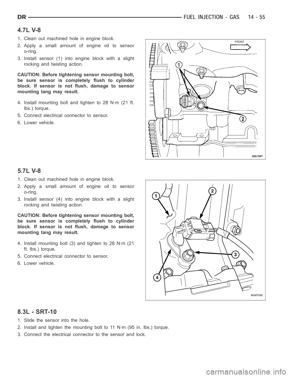
3. Install sensor (1) into engine block with a slight
rocking and twisting action.
CAUTION: Before tightening sensor mounting bolt,
be sure sensor is completely flush to cylinder
block. If sensor is not flush, damage to sensor
mounting tang may result.
4. Install mounting bolt and tighten to 28 Nꞏm (21 ft.
lbs.) torque.
5. Connect electrical connector to sensor.
6. Lower vehicle.
5.7L V-8
1. Clean out machined hole in engine block.
2. Apply a small amount of engine oil to sensor
o-ring.
3. Install sensor (4) into engine block with a slight
rocking and twisting action.
CAUTION: Before tightening sensor mounting bolt,
be sure sensor is completely flush to cylinder
block. If sensor is not flush, damage to sensor
mounting tang may result.
4. Install mounting bolt (3) and tighten to 28 Nꞏm (21
ft. lbs.) torque.
5. Connect electrical connector to sensor.
6. Lower vehicle.
8.3L - SRT-10
1. Slide the sensor into the hole.
2. Install and tighten the mounting bolt to 11 Nꞏm (95 in. lbs.) torque.
3. Connect the electrical connector to the sensor and lock.