2006 DODGE RAM SRT-10 oil filter
[x] Cancel search: oil filterPage 3878 of 5267
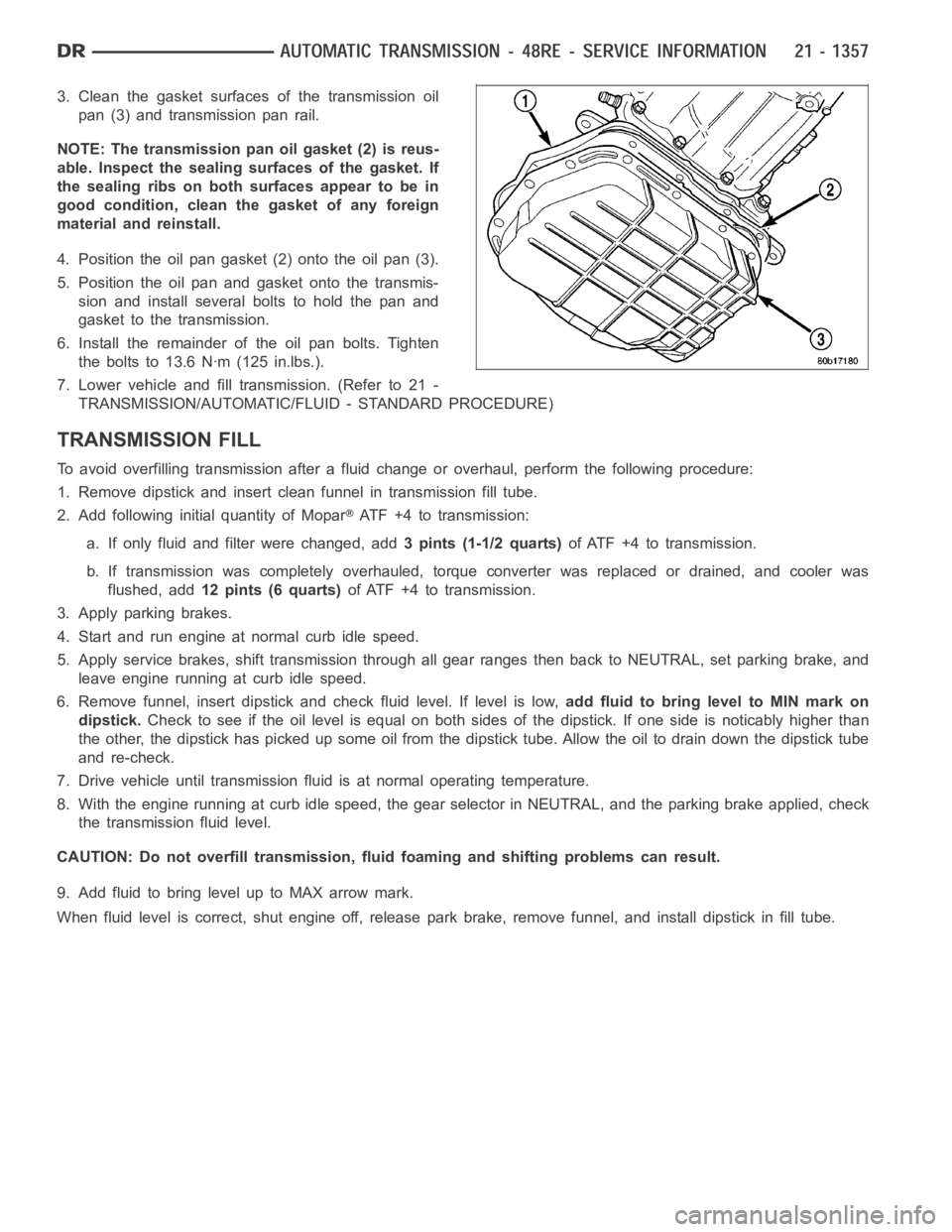
3. Clean the gasket surfaces of the transmission oil
pan (3) and transmission pan rail.
NOTE: The transmission pan oil gasket (2) is reus-
able. Inspect the sealing surfaces of the gasket. If
the sealing ribs on both surfaces appear to be in
good condition, clean the gasket of any foreign
material and reinstall.
4. Position the oil pan gasket (2) onto the oil pan (3).
5. Position the oil pan and gasket onto the transmis-
sion and install several bolts to hold the pan and
gasket to the transmission.
6. Install the remainder of the oil pan bolts. Tighten
the bolts to 13.6 Nꞏm (125 in.lbs.).
7. Lower vehicle and fill transmission. (Refer to 21 -
TRANSMISSION/AUTOMATIC/FLUID - STANDARD PROCEDURE)
TRANSMISSION FILL
To avoid overfilling transmission after a fluid change or overhaul, perform the following procedure:
1. Remove dipstick and insert clean funnel in transmission fill tube.
2. Add following initial quantity of Mopar
ATF+4totransmission:
a. If only fluid and filter were changed, add3 pints (1-1/2 quarts)of ATF +4 to transmission.
b. If transmission was completely overhauled, torque converter was replaced or drained, and cooler was
flushed, add12 pints (6 quarts)of ATF +4 to transmission.
3. Apply parking brakes.
4. Start and run engine at normal curb idle speed.
5. Apply service brakes, shift transmission through all gear ranges then back to NEUTRAL, set parking brake, and
leave engine running at curb idle speed.
6. Remove funnel, insert dipstick andcheck fluid level. If level is low,add fluid to bring level to MIN mark on
dipstick.Check to see if the oil level is equal on both sides of the dipstick. If one side is noticably higher than
the other, the dipstick has picked up some oil from the dipstick tube. Allowthe oil to drain down the dipstick tube
and re-check.
7. Drive vehicle until transmission fluid is at normal operating temperature.
8. With the engine running at curb idle speed, the gear selector in NEUTRAL,and the parking brake applied, check
the transmission fluid level.
CAUTION: Do not overfill transmission, fluid foaming and shifting problems can result.
9. Add fluid to bring level up to MAX arrow mark.
When fluid level is correct, shut engine off, release park brake, remove funnel, and install dipstick in fill tube.
Page 3993 of 5267
Manual lever detent ball.
Throttle lever.
Fluid filter.
Pressure adjusting screw bracket.
Governor pressure solenoid.
Governor pressure sensor (includes transmission temperature thermistor).
Converter clutch/overdrive solenoid assembly and harness.
Governor housing gasket.
Solenoid case connector O-rings.
1. Shift transmission into NEUTRAL.
2. Raise vehicle.
3. Remove gearshift and throttle levers from shaft of
valve body manual lever.
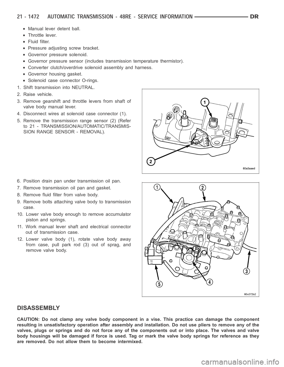
4. Disconnect wires at solenoid case connector (1).
5. Remove the transmission range sensor (2) (Refer
to 21 - TRANSMISSION/AUTOMATIC/TRANSMIS-
SION RANGE SENSOR - REMOVAL).
6. Position drain pan under transmission oil pan.
7. Remove transmission oil pan and gasket.
8. Remove fluid filter from valve body.
9. Remove bolts attaching valve body to transmission
case.
10. Lower valve body enough to remove accumulator
piston and springs.
11. Work manual lever shaft and electrical connector
out of transmission case.
12. Lower valve body (1), rotate valve body away
from case, pull park rod (3) out of sprag, and
remove valve body.
DISASSEMBLY
CAUTION: Do not clamp any valve body component in a vise. This practice can damage the component
resulting in unsatisfactory operation after assembly and installation.Do not use pliers to remove any of the
valves, plugs or springs and do not force any of the components out or into place. The valves and valve
body housings will be damaged if force is used. Tag or mark the valve body springs for reference as they
are removed. Do not allow them to become intermixed.
Page 4007 of 5267
sharpness of these edges is vitally important. The edges prevent foreign matter from lodging between the valves
and plugs and the bore.
Inspect all the valve and plug bores in the valve body. Use a penlight to viewthe bore interiors. Replace the valve
body if any bores are distorted or scored. Inspect all of the valve body springs. The springs must be free of dis-
tortion, warpage or broken coils.
Check the two separator plates for distortion or damage of any kind. Inspect the upper housing, lower housing, 3-4
accumulator housing, and transfer plate carefully. Be sure all fluid passages are clean and clear. Check condition of
the upper housing and transfer plate check balls as well. The check balls and ball seats must not be worn or dam-
aged.
Trial fit each valve and plug in its bore to check freedom of operation. Whenclean and dry, the valves and plugs
shoulddropfreelyintothebores.
Valve body bores do not change dimensionally with use. If the valve body functioned correctly when new, it will
continue to operate properly after cleaning and inspection. It should notbe necessary to replace a valve body
assembly unless it is damaged in handling.
The only serviceable valve body components are listed below. The remaining valve body components are serviced
only as part of a complete valve body assembly. Serviceable parts are:
dual solenoid and harness assembly
solenoid gasket
solenoid case connector O-rings and shoulder bolt
switch valve and spring
pressure adjusting screw and bracket assembly
throttle lever
manual lever and shaft seal
throttle lever shaft seal, washer, and E-clip
fluid filter and screws
detent ball and spring
valve body screws
governor pressure solenoid
governor pressure sensor and retaining clip
park lock rod and E-clip
ASSEMBLY
CAUTION: Do not force valves or plugs into place during reassembly. If the valve body bores, valves and
plugs are free of distortion or burrs, the valve body components should allslide into place easily. In addi-
tion, do not overtighten the transfer plate and valve body screws during reassembly. Overtightening can
distort the housings resulting in valve sticking, cross leakage and unsatisfactory operation. Tighten valve
body screws to recommended torque only.
Page 4018 of 5267
INSTALLATION
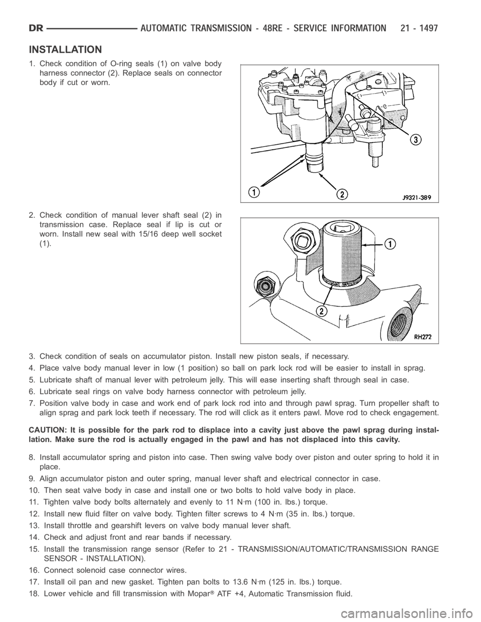
1. Check condition of O-ring seals (1) on valve body
harness connector (2). Replace seals on connector
body if cut or worn.
2. Check condition of manual lever shaft seal (2) in
transmission case. Replace seal if lip is cut or
worn. Install new seal with 15/16 deep well socket
(1).
3. Check condition of seals on accumulator piston. Install new piston seals, if necessary.
4. Place valve body manual lever in low (1 position) so ball on park lock rod will be easier to install in sprag.
5. Lubricate shaft of manual lever with petroleum jelly. This will ease inserting shaft through seal in case.
6. Lubricate seal rings on valve body harness connector with petroleum jelly.
7. Position valve body in case and work end of park lock rod into and through pawl sprag. Turn propeller shaft to
align sprag and park lock teeth if necessary. The rod will click as it enterspawl. Move rod to check engagement.
CAUTION: It is possible for the park rod to displace into a cavity just abovethe pawl sprag during instal-
lation. Make sure the rod is actually engaged in the pawl and has not displaced into this cavity.
8. Install accumulator spring and piston into case. Then swing valve body overpistonandouterspringtoholditin
place.
9. Align accumulator piston and outer spring, manual lever shaft and electrical connector in case.
10. Then seat valve body in case and install one or two bolts to hold valve bodyinplace.
11. Tighten valve body bolts alternately and evenly to 11 Nꞏm (100 in. lbs.)torque.
12. Install new fluid filter on valve body. Tighten filter screws to 4 Nꞏm (35 in. lbs.) torque.
13. Install throttle and gearshift levers on valve body manual lever shaft.
14. Check and adjust front and rear bands if necessary.
15. Install the transmission range sensor (Refer to 21 - TRANSMISSION/AUTOMATIC/TRANSMISSION RANGE
SENSOR - INSTALLATION).
16. Connect solenoid case connector wires.
17. Install oil pan and new gasket. Tighten pan bolts to 13.6 Nꞏm (125 in. lbs.) torque.
18. Lower vehicle and fill transmission with Mopar
ATF +4, Automatic Transmission fluid.
Page 5075 of 5267
REMOVAL
DENSO A/C COMPRESSOR
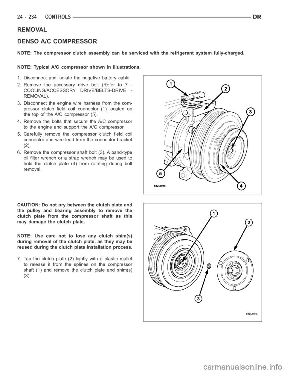
NOTE: The compressor clutch assembly can be serviced with the refrigerantsystem fully-charged.
NOTE: Typical A/C compressor shown in illustrations.
1. Disconnect and isolate the negative battery cable.
2. Remove the accessory drive belt (Refer to 7 -
COOLING/ACCESSORY DRIVE/BELTS-DRIVE -
REMOVAL).
3. Disconnect the engine wire harness from the com-
pressor clutch field coilconnector (1) located on
the top of the A/C compressor (5).
4. Remove the bolts that secure the A/C compressor
to the engine and support the A/C compressor.
5. Carefully remove the compressor clutch field coil
connector and wire lead from the connector bracket
(2).
6. Remove the compressor shaft bolt (3). A band-type
oil filter wrench or a strap wrench may be used to
hold the clutch plate (4) from rotating during bolt
removal.
CAUTION: Do not pry between the clutch plate and
the pulley and bearing assembly to remove the
clutch plate from the compressor shaft as this
may damage the clutch plate.
NOTE: Use care not to lose any clutch shim(s)
during removal of the clutch plate, as they may be
reused during the clutch plate installation process.
7. Tap the clutch plate (2) lightly with a plastic mallet
to release it from the splines on the compressor
shaft (1) and remove the clutch plate and shim(s)
(3).
Page 5133 of 5267
ACCUMULATOR-A/C
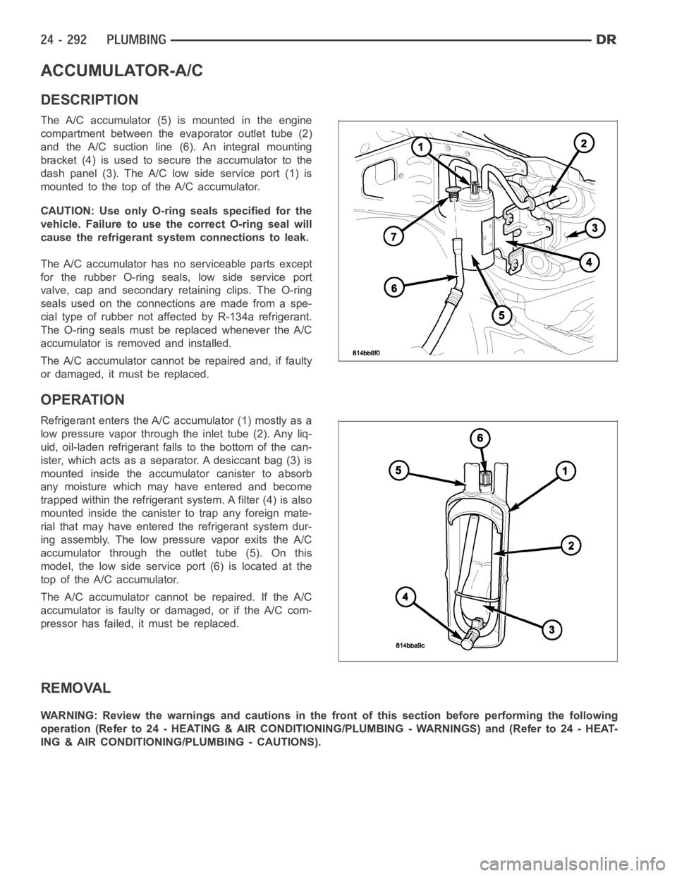
DESCRIPTION
The A/C accumulator (5) is mounted in the engine
compartment between the evaporator outlet tube (2)
and the A/C suction line (6). An integral mounting
bracket (4) is used to secure the accumulator to the
dash panel (3). The A/C low side service port (1) is
mountedtothetopoftheA/Caccumulator.
CAUTION: Use only O-ring seals specified for the
vehicle. Failure to use the correct O-ring seal will
cause the refrigerant system connections to leak.
The A/C accumulator has no serviceable parts except
for the rubber O-ring seals, low side service port
valve, cap and secondary retaining clips. The O-ring
seals used on the connections are made from a spe-
cial type of rubber not affected by R-134a refrigerant.
The O-ring seals must be replaced whenever the A/C
accumulator is removed and installed.
The A/C accumulator cannot be repaired and, if faulty
or damaged, it must be replaced.
OPERATION
Refrigerant enters the A/C accumulator (1) mostly as a
low pressure vapor through the inlet tube (2). Any liq-
uid, oil-laden refrigerant falls to the bottom of the can-
ister, which acts as a separator. A desiccant bag (3) is
mounted inside the accumulator canister to absorb
any moisture which may have entered and become
trapped within the refrigerant system. A filter (4) is also
mounted inside the canister to trap any foreign mate-
rial that may have entered the refrigerant system dur-
ing assembly. The low pressure vapor exits the A/C
accumulator through the outlet tube (5). On this
model, the low side service port (6) is located at the
top of the A/C accumulator.
The A/C accumulator cannot be repaired. If the A/C
accumulator is faulty or damaged, or if the A/C com-
pressor has failed, it must be replaced.
REMOVAL
WARNING: Review the warnings and cautions in the front of this section before performing the following
operation (Refer to 24 - HEATING & AIR CONDITIONING/PLUMBING - WARNINGS) and (Refer to 24 - HEAT-
ING & AIR CONDITIONING/PLUMBING - CAUTIONS).
Page 5134 of 5267
1. Disconnect and isolate the negative battery cable.
2. Recover the refrigerant from the refrigerant system
(Refer to 24 - HEATING & AIR CONDITIONING/
PLUMBING - STANDARD PROCEDURE -
REFRIGERANT RECOVERY).
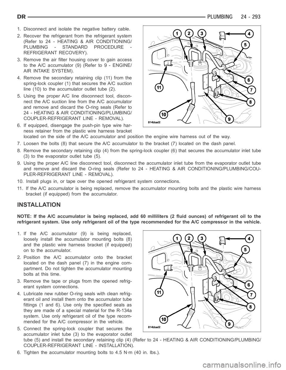
3. Remove the air filter housing cover to gain access
to the A/C accumulator (9) (Refer to 9 - ENGINE/
AIR INTAKE SYSTEM).
4. Remove the secondary retaining clip (11) from the
spring-lock coupler (1) that secures the A/C suction
line (10) to the accumulator outlet tube (2).
5. Using the proper A/C line disconnect tool, discon-
nect the A/C suction line from the A/C accumulator
and remove and discard the O-ring seals (Refer to
24 - HEATING & AIR CONDITIONING/PLUMBING/
COUPLER-REFRIGERANT LINE - REMOVAL).
6. If equipped, disengage the push-pin type wire har-
ness retainer from the plastic wire harness bracket
located on the side of the A/C accumulator and position the engine wire harness out of the way.
7. Loosen the bolts (8) that secure the A/C accumulator to the bracket (7) located on the dash panel.
8. Remove the secondary retaining clip (4) from the spring-lock coupler (6) that secures the accumulator inlet tube
(3) to the evaporator outlet tube (5).
9. Using the proper A/C line disconnect tool, disconnect the accumulator inlet tube from the evaporator outlet tube
and remove and discard the O-ring seals (Refer to 24 - HEATING & AIR CONDITIONING/PLUMBING/COU-
PLER-REFRIGERANT LINE - REMOVAL).
10. Install plugs in, or tape over the opened refrigerant system connections.
11. If the A/C accumulator is being replaced, remove the accumulator mounting bolts and the plastic wire harness
bracket (if equipped) from the accumulator.
INSTALLATION
NOTE: If the A/C accumulator is being replaced, add 60 milliliters (2 fluidounces) of refrigerant oil to the
refrigerant system. Use only refrigerant oil of the type recommended for the A/C compressor in the vehicle.
1. If the A/C accumulator (9) is being replaced,
loosely install the accumulator mounting bolts (8)
and the plastic wire harness bracket (if equipped)
on to the accumulator.
2. Position the A/C accumulator onto the bracket
located on the dash panel (7) in the engine com-
partment. Do not tighten the accumulator mounting
bolts at this time.
3. Remove the tape or plugs from the opened refrig-
erant system connections.
4. Lubricate new rubber O-ring seals with clean refrig-
erant oil and install them onto the accumulator tube
fittings (1 and 6). Use only the specified seals as
they are made of a special material for the R-134a
system. Use only refrigerant oil of the type recom-
mended for the A/C compressor in the vehicle.
5. Connect the spring-lock coupler that secures the
accumulator inlet tube (3) to the evaporator outlet
tube (5) and install the secondary retaining clip (4) (Refer to 24 - HEATING& AIR CONDITIONING/PLUMBING/
COUPLER-REFRIGERANT LINE - INSTALLATION).
6. Tighten the accumulator mounting bolts to 4.5 Nꞏm (40 in. lbs.).
Page 5168 of 5267
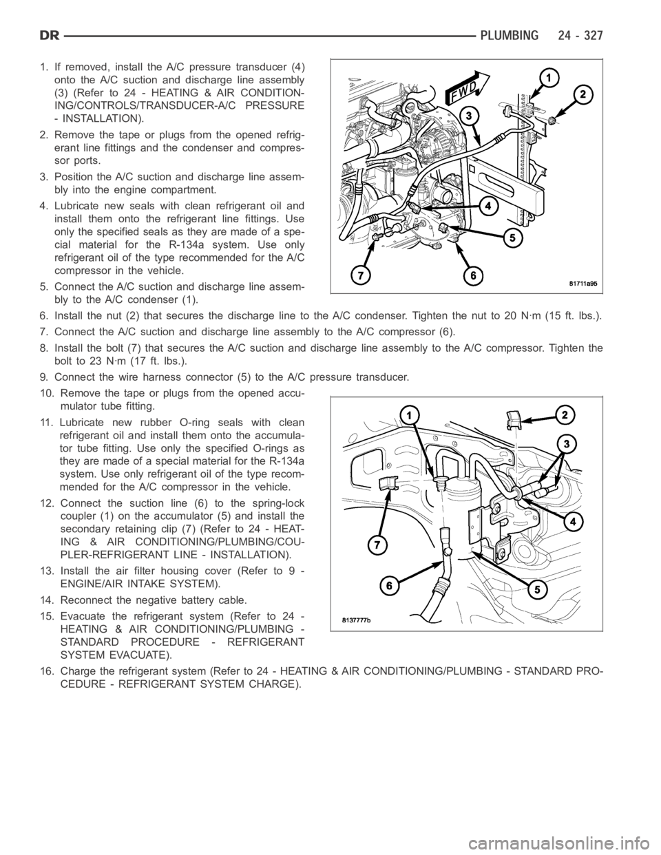
1. If removed, install the A/C pressure transducer (4)
onto the A/C suction and discharge line assembly
(3)(Referto24-HEATING&AIRCONDITION-
ING/CONTROLS/TRANSDUCER-A/C PRESSURE
- INSTALLATION).
2. Remove the tape or plugs from the opened refrig-
erant line fittings and the condenser and compres-
sor ports.
3. Position the A/C suction and discharge line assem-
bly into the engine compartment.
4. Lubricate new seals with clean refrigerant oil and
install them onto the refrigerant line fittings. Use
only the specified seals as they are made of a spe-
cial material for the R-134a system. Use only
refrigerant oil of the type recommended for the A/C
compressor in the vehicle.
5. Connect the A/C suction and discharge line assem-
bly to the A/C condenser (1).
6. Install the nut (2) that secures the discharge line to the A/C condenser.Tighten the nut to 20 Nꞏm (15 ft. lbs.).
7. Connect the A/C suction and discharge line assembly to the A/C compressor(6).
8. Install the bolt (7) that secures the A/C suction and discharge line assembly to the A/C compressor. Tighten the
boltto23Nꞏm(17ft.lbs.).
9. Connect the wire harness connector (5) to the A/C pressure transducer.
10. Remove the tape or plugs from the opened accu-
mulator tube fitting.
11. Lubricate new rubber O-ring seals with clean
refrigerant oil and install them onto the accumula-
tor tube fitting. Use only the specified O-rings as
they are made of a special material for the R-134a
system. Use only refrigerant oil of the type recom-
mended for the A/C compressor in the vehicle.
12. Connect the suction line (6) to the spring-lock
coupler (1) on the accumulator (5) and install the
secondary retaining clip (7) (Refer to 24 - HEAT-
ING & AIR CONDITIONING/PLUMBING/COU-
PLER-REFRIGERANT LINE - INSTALLATION).
13. Install the air filter housing cover (Refer to 9 -
ENGINE/AIR INTAKE SYSTEM).
14. Reconnect the negative battery cable.
15. Evacuate the refrigerant system (Refer to 24 -
HEATING & AIR CONDITIONING/PLUMBING -
STANDARD PROCEDURE - REFRIGERANT
SYSTEM EVACUATE).
16. Charge the refrigerant system (Refer to 24 - HEATING & AIR CONDITIONING/PLUMBING - STANDARD PRO-
CEDURE - REFRIGERANT SYSTEM CHARGE).