2006 DODGE RAM SRT-10 oil filter
[x] Cancel search: oil filterPage 3806 of 5267
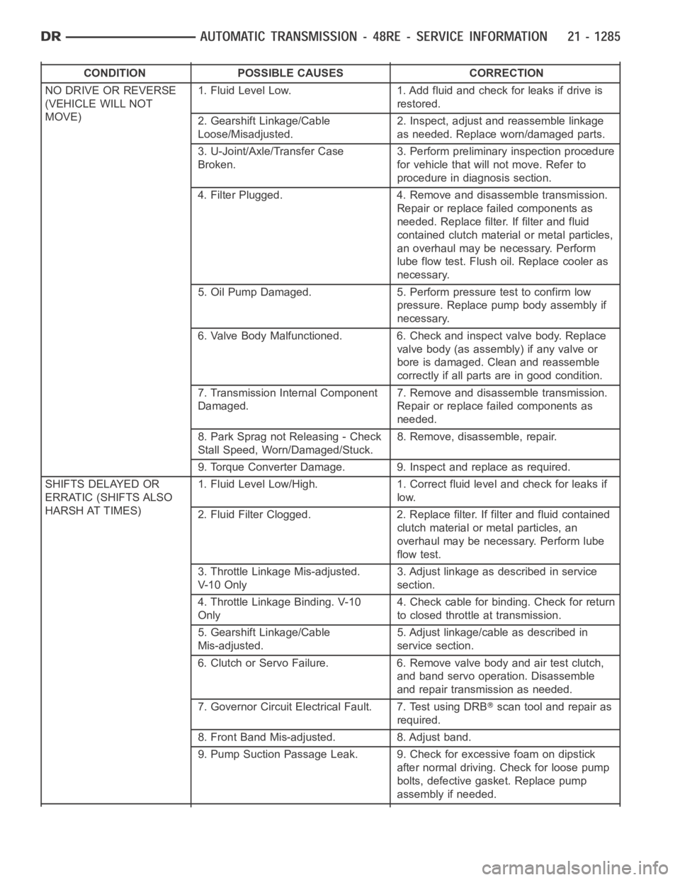
CONDITION POSSIBLE CAUSES CORRECTION
NO DRIVE OR REVERSE
(VEHICLE WILL NOT
MOVE)1. Fluid Level Low. 1. Add fluid and check for leaks if drive is
restored.
2. Gearshift Linkage/Cable
Loose/Misadjusted.2. Inspect, adjust and reassemble linkage
as needed. Replace worn/damaged parts.
3. U-Joint/Axle/Transfer Case
Broken.3. Perform preliminary inspection procedure
for vehicle that will not move. Refer to
procedure in diagnosis section.
4. Filter Plugged. 4. Remove and disassemble transmission.
Repair or replace failed components as
needed. Replace filter. If filter and fluid
contained clutch material or metal particles,
an overhaul may be necessary. Perform
lube flow test. Flush oil. Replace cooler as
necessary.
5. Oil Pump Damaged. 5. Perform pressure test to confirm low
pressure. Replace pump body assembly if
necessary.
6. Valve Body Malfunctioned. 6. Check and inspect valve body. Replace
valve body (as assembly) if any valve or
bore is damaged. Clean and reassemble
correctly if all parts are in good condition.
7. Transmission Internal Component
Damaged.7. Remove and disassemble transmission.
Repair or replace failed components as
needed.
8. Park Sprag not Releasing - Check
Stall Speed, Worn/Damaged/Stuck.8. Remove, disassemble, repair.
9. Torque Converter Damage. 9. Inspect and replace as required.
SHIFTS DELAYED OR
ERRATIC (SHIFTS ALSO
HARSH AT TIMES)1. Fluid Level Low/High. 1. Correct fluid level and check for leaks if
low.
2. Fluid Filter Clogged. 2. Replace filter. If filter and fluid contained
clutch material or metal particles, an
overhaul may be necessary. Perform lube
flow test.
3. Throttle Linkage Mis-adjusted.
V- 1 0 O n l y3. Adjust linkage as described in service
section.
4. Throttle Linkage Binding. V-10
Only4. Check cable for binding. Check for return
to closed throttle at transmission.
5. Gearshift Linkage/Cable
Mis-adjusted.5. Adjust linkage/cable as described in
service section.
6. Clutch or Servo Failure. 6. Remove valve body and air test clutch,
and band servo operation. Disassemble
and repair transmission as needed.
7. Governor Circuit Electrical Fault. 7. Test using DRB
scan tool and repair as
required.
8. Front Band Mis-adjusted. 8. Adjust band.
9. Pump Suction Passage Leak. 9. Check for excessive foam on dipstick
after normal driving. Check for loose pump
bolts, defective gasket. Replace pump
assembly if needed.
Page 3809 of 5267
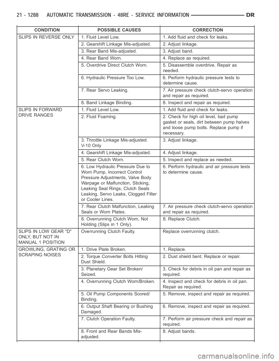
CONDITION POSSIBLE CAUSES CORRECTION
SLIPS IN REVERSE ONLY 1. Fluid Level Low. 1. Add fluid and check for leaks.
2. Gearshift Linkage Mis-adjusted. 2. Adjust linkage.
3. Rear Band Mis-adjusted. 3. Adjust band.
4. Rear Band Worn. 4. Replace as required.
5. Overdrive Direct Clutch Worn. 5. Disassemble overdrive. Repair as
needed.
6. Hydraulic Pressure Too Low. 6. Perform hydraulic pressure tests to
determine cause.
7. Rear Servo Leaking. 7. Air pressure check clutch-servo operation
and repair as required.
8. Band Linkage Binding. 8. Inspect and repair as required.
SLIPS IN FORWARD
DRIVE RANGES1. Fluid Level Low. 1. Add fluid and check for leaks.
2. Fluid Foaming. 2. Check for high oil level, bad pump
gasket or seals, dirt between pump halves
and loose pump bolts. Replace pump if
necessary.
3. Throttle Linkage Mis-adjusted.
V- 1 0 O n l y3. Adjust linkage.
4. Gearshift Linkage Mis-adjusted. 4. Adjust linkage.
5. Rear Clutch Worn. 5. Inspect and replace as needed.
6. Low Hydraulic Pressure Due to
Worn Pump, Incorrect Control
Pressure Adjustments, Valve Body
Warpage or Malfunction, Sticking,
Leaking Seal Rings, Clutch Seals
Leaking, Servo Leaks, Clogged Filter
or Cooler Lines.6. Perform hydraulic and air pressure tests
to determine cause.
7. Rear Clutch Malfunction, Leaking
Seals or Worn Plates.7. Air pressure check clutch-servo operation
and repair as required.
8. Overrunning Clutch Worn, Not
Holding (Slips in 1 Only).8. Replace Clutch.
SLIPS IN LOW GEAR
D
ONLY, BUT NOT IN
MANUAL 1 POSITIONOverrunning Clutch Faulty. Replace overrunning clutch.
GROWLING, GRATING OR
SCRAPING NOISES1. Drive Plate Broken. 1. Replace.
2. Torque Converter Bolts Hitting
Dust Shield.2. Dust shield bent. Replace or repair.
3. Planetary Gear Set Broken/
Seized.3. Check for debris in oil pan and repair as
required.
4. Overrunning Clutch Worn/Broken. 4. Inspect and check for debris in oil pan.
Repair as required.
5. Oil Pump Components Scored/
Binding.5. Remove, inspect and repair as required.
6. Output Shaft Bearing or Bushing
Damaged.6. Remove, inspect and repair as required.
7. Clutch Operation Faulty. 7. Perform air pressure check and repair as
required.
8. Front and Rear Bands Mis-
adjusted.8. Adjust bands.
Page 3820 of 5267
4. Removetheoverdriveunitfromthemaintransmis-
sion case. If overdrive unit is not to be serviced,
install Alignment Shaft 6227-2 into the overdrive
unit to prevent misalignment of the overdrive
clutches during service ofmain transmission com-
ponents.
5. Remove throttle and shift levers from valve body
manual shaft and throttle lever shaft.
6. Remove transmission oil pan and gasket.
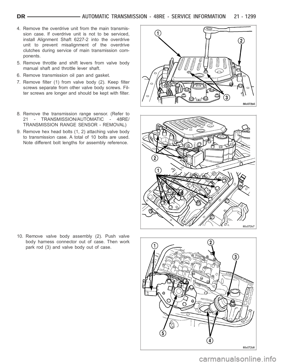
7. Remove filter (1) from valve body (2). Keep filter
screws separate from other valve body screws. Fil-
ter screws are longer and should be kept with filter.
8. Remove the transmission range sensor. (Refer to
21 - TRANSMISSION/AUTOMATIC - 48RE/
TRANSMISSION RANGE SENSOR - REMOVAL)
9. Remove hex head bolts (1, 2) attaching valve body
to transmission case. A total of 10 bolts are used.
Note different bolt lengths for assembly reference.
10. Remove valve body assembly (2). Push valve
body harness connector out of case. Then work
park rod (3) and valve body out of case.
Page 3836 of 5267
ACCUMULATOR, VALVE BODY, OIL PAN, AND TORQUE CONVERTER
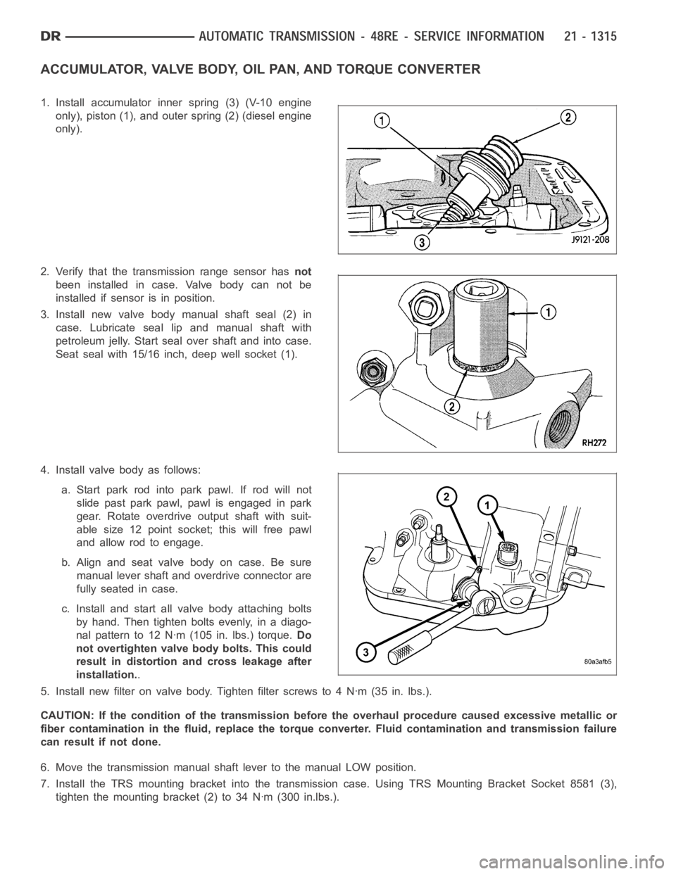
1. Install accumulator inner spring (3) (V-10 engine
only), piston (1), and outer spring (2) (diesel engine
only).
2. Verify that the transmission range sensor hasnot
been installed in case. Valve body can not be
installed if sensor is in position.
3. Install new valve body manual shaft seal (2) in
case. Lubricate seal lip and manual shaft with
petroleum jelly. Start seal over shaft and into case.
Seat seal with 15/16 inch, deep well socket (1).
4. Install valve body as follows:
a. Start park rod into park pawl. If rod will not
slide past park pawl, pawl is engaged in park
gear. Rotate overdrive output shaft with suit-
able size 12 point socket; this will free pawl
and allow rod to engage.
b.Alignandseatvalvebodyoncase.Besure
manual lever shaft and overdrive connector are
fully seated in case.
c. Install and start all valve body attaching bolts
by hand. Then tighten bolts evenly, in a diago-
nal pattern to 12 Nꞏm (105 in. lbs.) torque.Do
not overtighten valve body bolts. This could
result in distortion and cross leakage after
installation..
5. Install new filter on valve body. Tighten filter screws to 4 Nꞏm (35 in. lbs.).
CAUTION: If the condition of the transmission before the overhaul procedure caused excessive metallic or
fiber contamination in the fluid, replace the torque converter. Fluid contamination and transmission failure
can result if not done.
6. Move the transmission manual shaft lever to the manual LOW position.
7. Install the TRS mounting bracket into the transmission case. Using TRS Mounting Bracket Socket 8581 (3),
tighten the mounting bracket (2) to 34 Nꞏm (300 in.lbs.).
Page 3858 of 5267
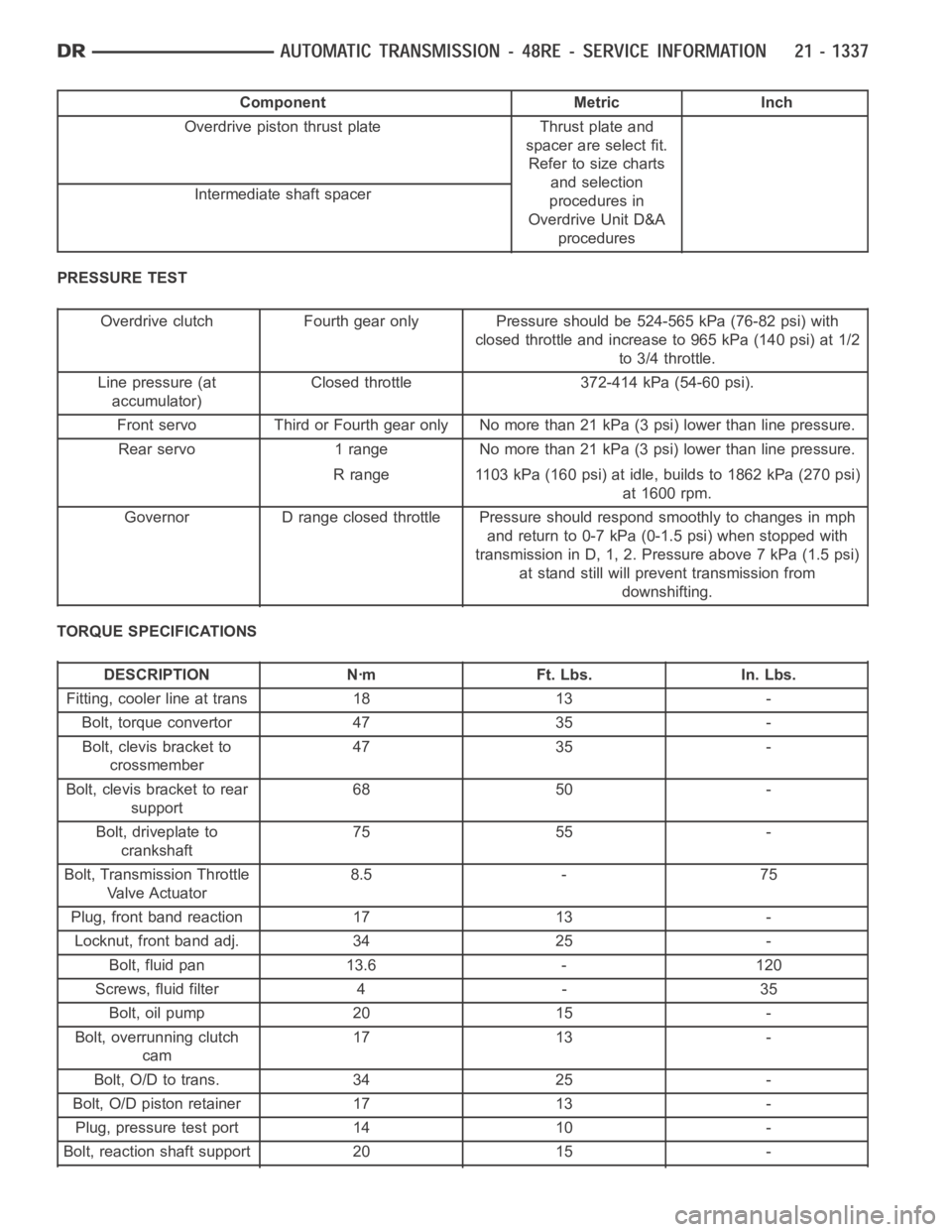
Component Metric Inch
Overdrive piston thrust plate Thrust plate and
spacer are select fit.
Refer to size charts
and selection
procedures in
Overdrive Unit D&A
procedures Intermediateshaft spacer
PRESSURE TEST
Overdrive clutch Fourth gear only Pressure should be 524-565 kPa (76-82 psi) with
closed throttle and increase to 965 kPa (140 psi) at 1/2
to 3/4 throttle.
Line pressure (at
accumulator)Closed throttle 372-414 kPa (54-60 psi).
Front servo Third or Fourth gear only No more than 21 kPa (3 psi) lower than line pressure.
Rearservo 1range Nomorethan21kPa(3psi)lowerthanlinepressure.
R range 1103 kPa (160 psi) at idle, builds to 1862 kPa (270 psi)
at 1600 rpm.
Governor D range closed throttle Pressure should respond smoothly to changes in mph
andreturnto0-7kPa(0-1.5psi)whenstoppedwith
transmission in D, 1, 2. Pressure above 7 kPa (1.5 psi)
at stand still will prevent transmission from
downshifting.
TORQUE SPECIFICATIONS
DESCRIPTION Nꞏm Ft. Lbs. In. Lbs.
Fitting, cooler line at trans 18 13 -
Bolt, torque convertor 47 35 -
Bolt, clevis bracket to
crossmember47 35 -
Bolt, clevis bracket to rear
support68 50 -
Bolt, driveplate to
crankshaft75 55 -
Bolt, Transmission Throttle
Va l v e A c t u a t o r8.5 - 75
Plug, front band reaction 17 13 -
Locknut, front band adj. 34 25 -
Bolt, fluid pan 13.6 - 120
Screws, fluid filter 4 - 35
Bolt, oil pump 20 15 -
Bolt, overrunning clutch
cam17 13 -
Bolt, O/D to trans. 34 25 -
Bolt, O/D piston retainer 17 13 -
Plug, pressure test port 14 10 -
Bolt, reaction shaft support 20 15 -
Page 3874 of 5267
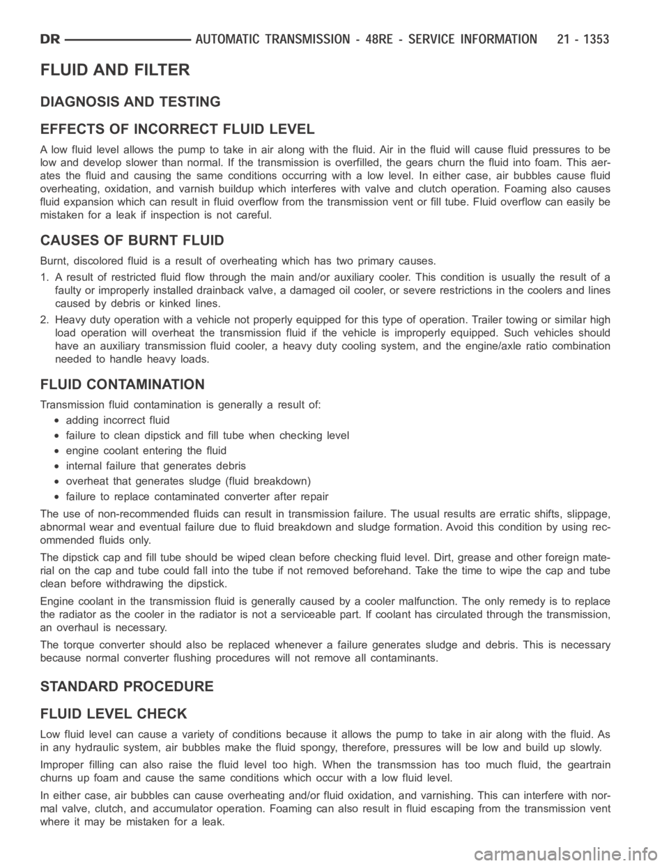
FLUID AND FILTER
DIAGNOSIS AND TESTING
EFFECTS OF INCORRECT FLUID LEVEL
Alowfluidlevelallowsthepumptotakeinairalongwiththefluid.Airinthe fluid will cause fluid pressures to be
low and develop slower than normal. If the transmission is overfilled, thegears churn the fluid into foam. This aer-
ates the fluid and causing the same conditions occurring with a low level. In either case, air bubbles cause fluid
overheating, oxidation, and varnish buildup which interferes with valveand clutch operation. Foaming also causes
fluid expansion which can result in fluid overflow from the transmission vent or fill tube. Fluid overflow can easily be
mistaken for a leak if inspection is not careful.
CAUSES OF BURNT FLUID
Burnt, discolored fluid is a result of overheating which has two primary causes.
1. A result of restricted fluid flow through the main and/or auxiliary cooler. This condition is usually the result of a
faulty or improperly installed drainback valve, a damaged oil cooler, or severe restrictions in the coolers and lines
caused by debris or kinked lines.
2. Heavy duty operation with a vehicle not properly equipped for this type of operation. Trailer towing or similar high
load operation will overheat the transmission fluid if the vehicle is improperly equipped. Such vehicles should
have an auxiliary transmission fluid cooler, a heavy duty cooling system,and the engine/axle ratio combination
needed to handle heavy loads.
FLUID CONTAMINATION
Transmission fluid contamination is generally a result of:
adding incorrect fluid
failure to clean dipstick and fill tube when checking level
engine coolant entering the fluid
internal failure that generates debris
overheat that generates sludge (fluid breakdown)
failure to replace contaminated converter after repair
The use of non-recommended fluids can result in transmission failure. Theusual results are erratic shifts, slippage,
abnormal wear and eventual failure due to fluid breakdown and sludge formation. Avoid this condition by using rec-
ommended fluids only.
The dipstick cap and fill tube should be wiped clean before checking fluid level. Dirt, grease and other foreign mate-
rial on the cap and tube could fall into the tube if not removed beforehand. Take the time to wipe the cap and tube
clean before withdrawing the dipstick.
Engine coolant in the transmission fluid is generally caused by a cooler malfunction. The only remedy is to replace
the radiator as the cooler in the radiator is not a serviceable part. If coolant has circulated through the transmission,
an overhaul is necessary.
The torque converter should also be replaced whenever a failure generatessludge and debris. This is necessary
because normal converter flushing procedures will not remove all contaminants.
STANDARD PROCEDURE
FLUID LEVEL CHECK
Low fluid level can cause a variety of conditions because it allows the pumpto take in air along with the fluid. As
in any hydraulic system, air bubbles make the fluid spongy, therefore, pressures will be low and build up slowly.
Improper filling can also raise the fluid level too high. When the transmssion has too much fluid, the geartrain
churns up foam and cause the same conditions which occur with a low fluid level.
In either case, air bubbles can cause overheating and/or fluid oxidation,and varnishing. This can interfere with nor-
mal valve, clutch, and accumulator operation. Foaming can also result in fluid escaping from the transmission vent
where it may be mistaken for a leak.
Page 3876 of 5267

PROCEDURE TWO
1. Start engine and apply parking brake.
2. Shift the transmission into DRIVE for approximately 2 seconds.
3. Shift the transmission into REVERSE for approximately 2 seconds.
4. Shift the transmission into PARK.
5. Hook up DRB
scan tool and select engine.
6. Select sensors.
7. Read the transmission temperature value.
8. Compare the fluid temperature value with the chart.
9. Adjust transmission fluid level shown on the dipstick according to the chart.
NOTE: After adding any fluid to the transmission, wait a minimum of 2 minutes for the oil to fully drain from
the fill tube into the transmission before rechecking the fluid level.
10. Check transmission for leaks.
FLUID AND FILTER REPLACEMENT
For proper service intervals (Refer to LUBRICATION & MAINTENANCE/MAINTENANCE SCHEDULES - DESCRIP-
TION). The service fluid fill after a filter change is approximately 3.8 liters (4.0 quarts).
Page 3877 of 5267
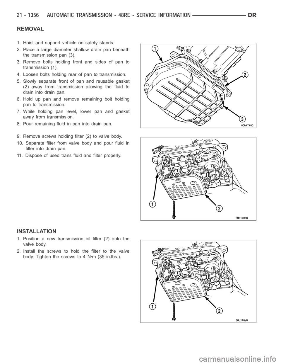
REMOVAL
1. Hoist and support vehicle on safety stands.
2. Place a large diameter shallow drain pan beneath
the transmission pan (3).
3. Remove bolts holding front and sides of pan to
transmission (1).
4. Loosen bolts holding rear of pan to transmission.
5. Slowly separate front of pan and reusable gasket
(2) away from transmission allowing the fluid to
drain into drain pan.
6. Hold up pan and remove remaining bolt holding
pan to transmission.
7. While holding pan level, lower pan and gasket
away from transmission.
8. Pour remaining fluid in pan into drain pan.
9. Remove screws holding filter (2) to valve body.
10. Separate filter from valve body and pour fluid in
filter into drain pan.
11. Dispose of used trans fluid and filter properly.
INSTALLATION
1. Position a new transmission oil filter (2) onto the
valve body.
2. Install the screws to hold the filter to the valve
body. Tighten the screws to 4 Nꞏm (35 in.lbs.).