2006 DODGE RAM SRT-10 oil filter
[x] Cancel search: oil filterPage 3462 of 5267
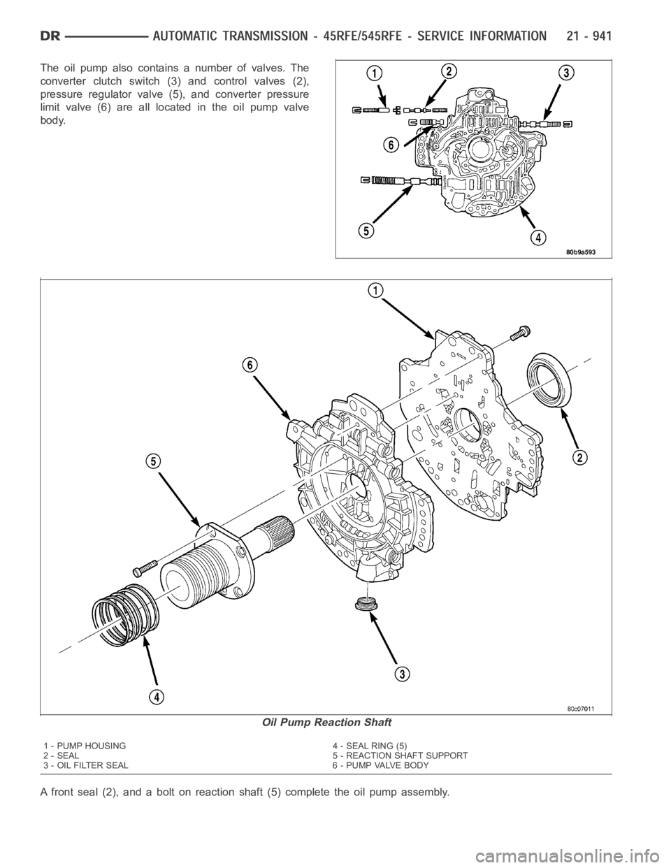
The oil pump also contains a number of valves. The
converter clutch switch (3) and control valves (2),
pressure regulator valve (5), and converter pressure
limit valve (6) are all located in the oil pump valve
body.
A front seal (2), and a bolt on reaction shaft (5) complete the oil pump assembly.
Oil Pump Reaction Shaft
1 - PUMP HOUSING 4 - SEAL RING (5)
2 - SEAL 5 - REACTION SHAFT SUPPORT
3 - OIL FILTER SEAL 6 - PUMP VALVE BODY
Page 3464 of 5267
DISASSEMBLY
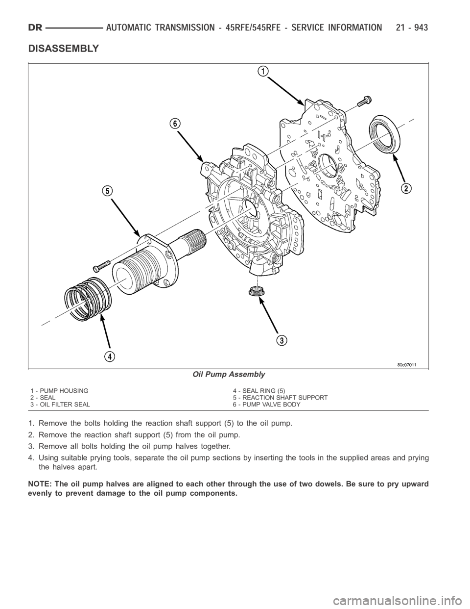
1. Remove the bolts holding the reaction shaft support (5) to the oil pump.
2. Remove the reaction shaft support (5) from the oil pump.
3. Remove all bolts holding the oil pump halves together.
4. Using suitable prying tools, separate the oil pump sections by inserting the tools in the supplied areas and prying
the halves apart.
NOTE: The oil pump halves are aligned to each other through the use of two dowels. Be sure to pry upward
evenly to prevent damage to the oil pump components.
Oil Pump Assembly
1 - PUMP HOUSING 4 - SEAL RING (5)
2 - SEAL 5 - REACTION SHAFT SUPPORT
3 - OIL FILTER SEAL 6 - PUMP VALVE BODY
Page 3470 of 5267
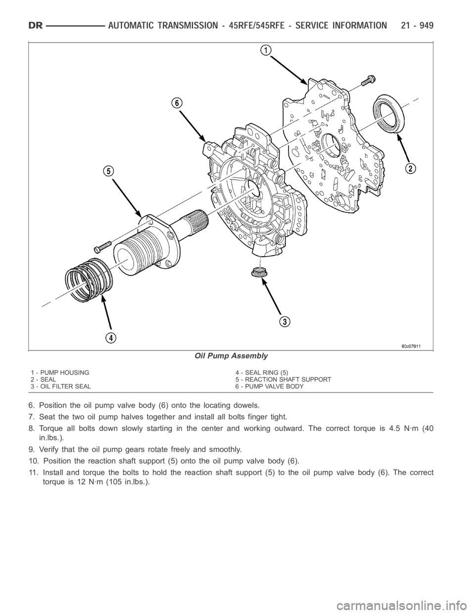
6. Position the oil pump valve body (6) onto the locating dowels.
7. Seat the two oil pump halves together and install all bolts finger tight.
8. Torque all bolts down slowly starting in the center and working outward.The correct torque is 4.5 Nꞏm (40
in.lbs.).
9. Verify that the oil pump gears rotate freely and smoothly.
10. Position the reaction shaft support (5) onto the oil pump valve body (6).
11. Install and torque the bolts to hold the reaction shaft support (5) to the oil pump valve body (6). The correct
torque is 12 Nꞏm (105 in.lbs.).
Oil Pump Assembly
1 - PUMP HOUSING 4 - SEAL RING (5)
2 - SEAL 5 - REACTION SHAFT SUPPORT
3 - OIL FILTER SEAL 6 - PUMP VALVE BODY
Page 3497 of 5267
LOW/REVERSE SWITCH VALVE
The low/reverse switch valve allows the low/reverse clutch to be operatedby either the LR/CC solenoid or the MS
solenoid.
REMOVAL
NOTE: The valve body can be removed for service without having to remove thetransmission assembly.
The valve body can be disassembled for cleaning and inspection of the individual components. (Refer to 21
- TRANSMISSION/AUTOMATIC - 45RFE/VALVE BODY - DISASSEMBLY)
1. Shift transmission into PARK.
2. Raise vehicle.
3. Disconnect wires at the solenoid and pressure
switch assembly connector.
4. Position drain pan under transmission oil pan.
5. Remove transmission oil pan.
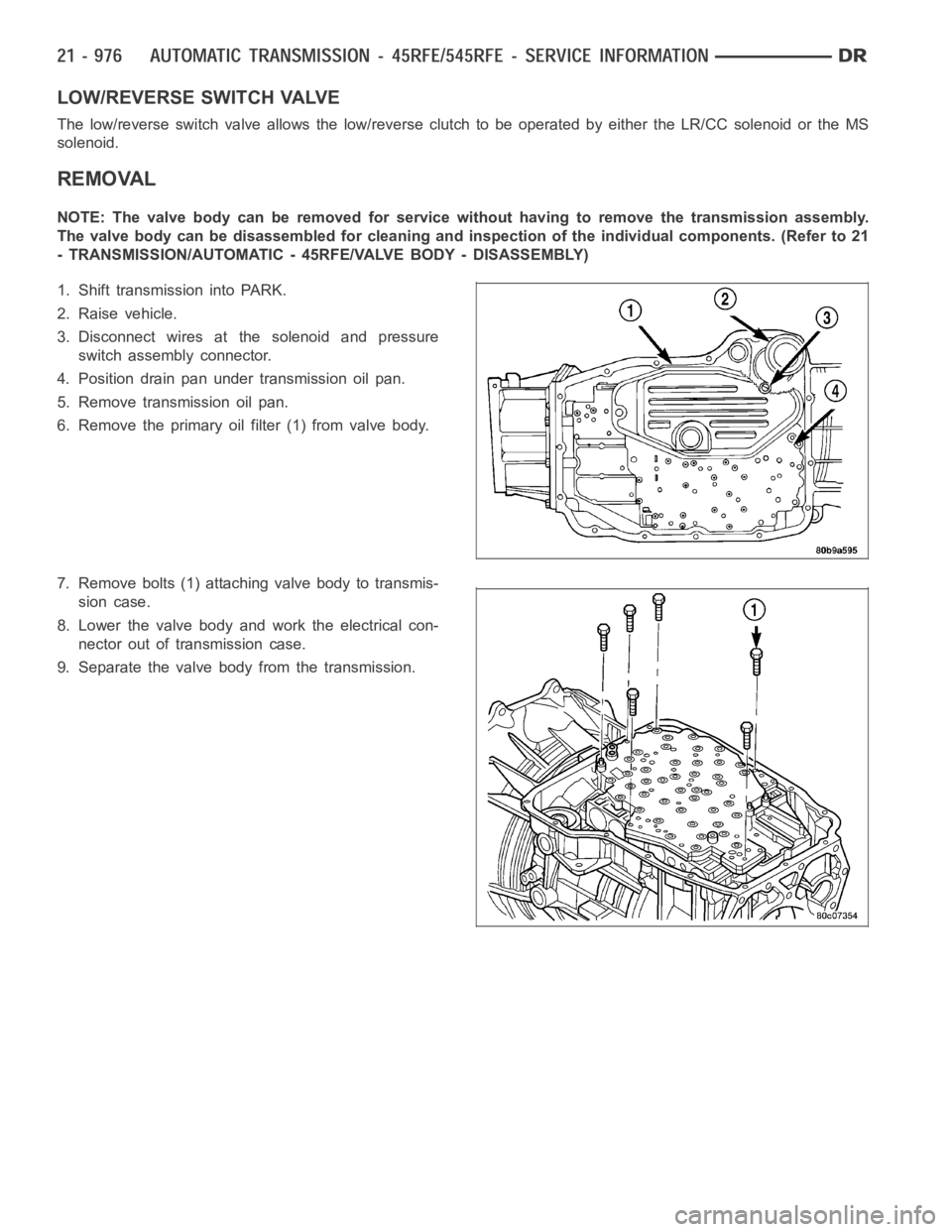
6. Remove the primary oil filter (1) from valve body.
7. Remove bolts (1) attaching valve body to transmis-
sion case.
8. Lower the valve body and work the electrical con-
nector out of transmission case.
9. Separate the valve body from the transmission.
Page 3507 of 5267
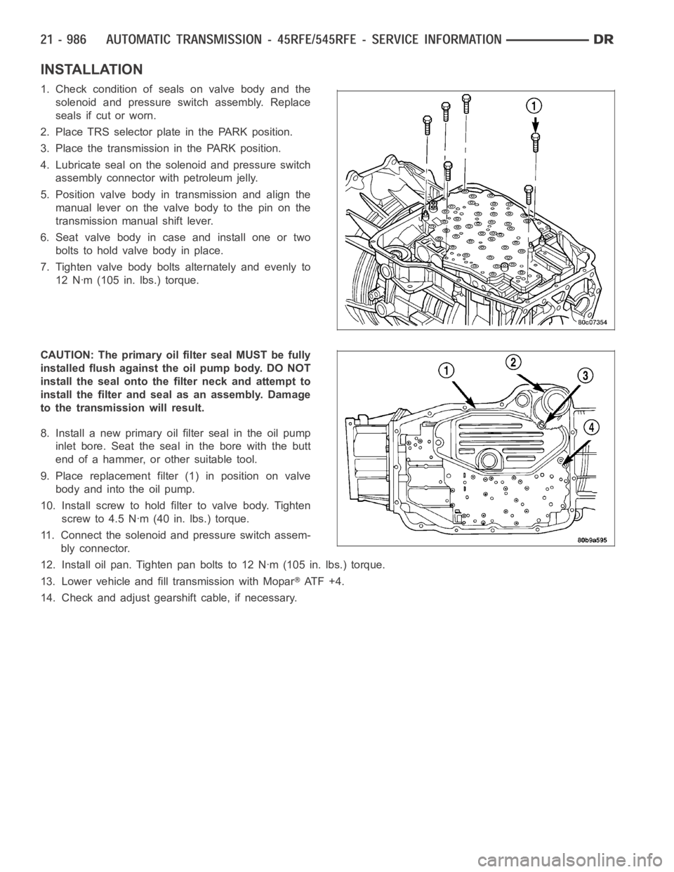
INSTALLATION
1. Check condition of seals on valve body and the
solenoid and pressure switch assembly. Replace
seals if cut or worn.
2. Place TRS selector plate in the PARK position.
3. Place the transmission in the PARK position.
4. Lubricate seal on the solenoid and pressure switch
assembly connector with petroleum jelly.
5. Position valve body in transmission and align the
manual lever on the valve body to the pin on the
transmission manual shift lever.
6. Seat valve body in case and install one or two
bolts to hold valve body in place.
7. Tighten valve body bolts alternately and evenly to
12 Nꞏm (105 in. lbs.) torque.
CAUTION: The primary oil filter seal MUST be fully
installed flush against the oil pump body. DO NOT
install the seal onto the filter neck and attempt to
install the filter and seal as an assembly. Damage
to the transmission will result.
8. Install a new primary oil filter seal in the oil pump
inlet bore. Seat the seal in the bore with the butt
end of a hammer, or other suitable tool.
9. Place replacement filter (1) in position on valve
body and into the oil pump.
10. Install screw to hold filter to valve body. Tighten
screw to 4.5 Nꞏm (40 in. lbs.) torque.
11. Connect the solenoid and pressure switch assem-
bly connector.
12. Install oil pan. Tighten pan bolts to 12 Nꞏm (105 in. lbs.) torque.
13. Lower vehicle and fill transmission with Mopar
AT F + 4 .
14. Check and adjust gearshift cable, if necessary.
Page 3787 of 5267
page page
AUTOMATIC TRANSMISSION - 48RE - SERVICE
INFORMATION
DESCRIPTION ............................. 1268
OPERATION ............................... 1271
DIAGNOSIS AND TESTING
AUTOMATIC TRANSMISSION .............. 1277
PRELIMINARY ............................ 1277
ROAD TESTING .......................... 1277
HYDRAULIC PRESSURE TEST . ........... 1278
AIR TESTING TRANSMISSION CLUTCH
AND BAND OPERATION................... 1281
CONVERTER HOUSING FLUID LEAK ...... 1282
DIAGNOSIS CHARTS ..................... 1283
STANDARD PROCEDURE - ALUMINUM
THREAD REPAIR ......................... 1293
REMOVAL ................................. 1294
DISASSEMBLY ............................. 1298
CLEANING ................................. 1306
INSPECTION ............................... 1306
ASSEMBLY . ............................... 1307
INSTALLATION ............................. 1317
SCHEMATICS AND DIAGRAMS
HYDRAULIC SCHEMATICS ................ 1322
SPECIFICATIONS
TRANSMISSION .......................... 1336
SPECIAL TOOLS
RE TRANSMISSION ...................... 1339
ACCUMULATOR
DESCRIPTION ............................. 1341
OPERATION ............................... 1342
INSPECTION ............................... 1342
BANDS
DESCRIPTION ............................. 1343
OPERATION ............................... 1343
ADJUSTMENTS
ADJUSTMENT - BANDS ................... 1344
SYSTEM-BRAKE TRANSMISSION SHIFT
INTERLOCK
DESCRIPTION ............................. 1345
OPERATION ............................... 1345
DIAGNOSIS AND TESTING - BRAKE
TRANSMISSION SHIFT INTERLOCK ........ 1345
ADJUSTMENTS - BRAKE TRANSMISSION
SHIFT INTERLOCK ....................... 1345
GOVERNOR-ELECTRONIC
DESCRIPTION ............................. 1347
OPERATION ............................... 1348
REMOVAL ................................. 1349
INSTALLATION ............................. 1350SEAL-EXTENSION HOUSING
REMOVAL ................................. 1352
INSTALLATION ............................. 1352
FLUID AND FILTER
DIAGNOSIS AND TESTING
EFFECTS OF INCORRECT FLUID LEVEL . . . 1353
CAUSES OF BURNT FLUID ............... 1353
FLUID CONTAMINATION .................. 1353
STANDARD PROCEDURE
FLUID LEVEL CHECK ..................... 1353
FLUID AND FILTER REPLACEMENT ....... 1355
TRANSMISSION FILL ..................... 1357
CLUTCH-FRONT
DESCRIPTION ............................. 1358
OPERATION ............................... 1358
DISASSEMBLY . ............................ 1359
INSPECTION............................... 1360
ASSEMBLY................................ 1360
SERVO-FRONT
DESCRIPTION ............................. 1363
OPERATION ............................... 1363
DISASSEMBLY . ............................ 1364
CLEANING ................................. 1364
INSPECTION ............................... 1365
ASSEMBLY................................ 1365
CABLE-GEARSHIFT
DIAGNOSIS AND TESTING - GEARSHIFT
CABLE ................................... 1366
REMOVAL ................................. 1366
INSTALLATION ............................. 1367
ADJUSTMENTS - GEARSHIFT CABLE ........ 1368
PUMP-OIL
DESCRIPTION ............................. 1369
OPERATION ............................... 1369
DISASSEMBLY ............................. 1370
CLEANING ................................. 1371
INSPECTION ............................... 1371
ASSEMBLY................................ 1373
BEARING-OUTPUT SHAFT FRONT
REMOVAL ................................. 1375
INSTALLATION ............................. 1375
BEARING-OUTPUT SHAFT REAR
REMOVAL ................................. 1376
INSTALLATION ............................. 1376
CLUTCH-OVERDRIVE
DESCRIPTION ............................. 1377
OPERATION ............................... 1377
UNIT-OVERDRIVE
REMOVAL ................................. 1378
DISASSEMBLY ............................. 1379
Page 3802 of 5267
3. Lower vehicle.
4. Turn OD switch on.
5. Secure test gauge so it can be viewed from drivers seat.
6. Start engine and shift into D range.
7. Increase vehicle speed gradually until 3-4 shift occurs and note gauge pressure.
8. Pressure should be 524-565 kPa (76-82 psi) with closed throttle and increase to 690-896 kPa (100-130 psi) at
1/2to3/4throttle.Notethatpressurecanincreasetoaround965kPa(140psi) at full throttle.
9. Return to shop or move vehicle off chassis dyno.
PRESSURE TEST ANALYSIS CHART
TEST CONDITION INDICATION
Line pressure OK during any one test Pump and regulator valve OK
Line pressure OK in R but low in D, 2, 1 Leakage in rear clutch area (seal rings, clutch seals)
Pressure low in D Fourth Gear Range Overdrive clutch piston seal, or check ball problem
Pressure OK in 1, 2 but low in D3 and R Leakage in front clutch area
Pressure OK in 2 but low in R and 1 Leakage in rear servo
Front servo pressure in 2 Leakage in servo; broken servo ring or cracked servo
piston
Pressure low in all positions Clogged filter, stuck regulator valve, wornor faulty
pump, low oil level
Governor pressure too high at idle speed Governor pressure solenoid valvesystem fault. Refer
to diagnostic book.
Governor pressure low at all mph figures Faulty governor pressure solenoid, transmission
control module, or governor pressure sensor
Lubrication pressure low at all throttle positions Clogged fluid cooler or lines, seal rings leaking, worn
pump bushings, pump, clutch retainer, or clogged filter.
Line pressure high Output shaft plugged, sticky regulator valve
Line pressure low Sticky regulator valve, clogged filter, worn pump
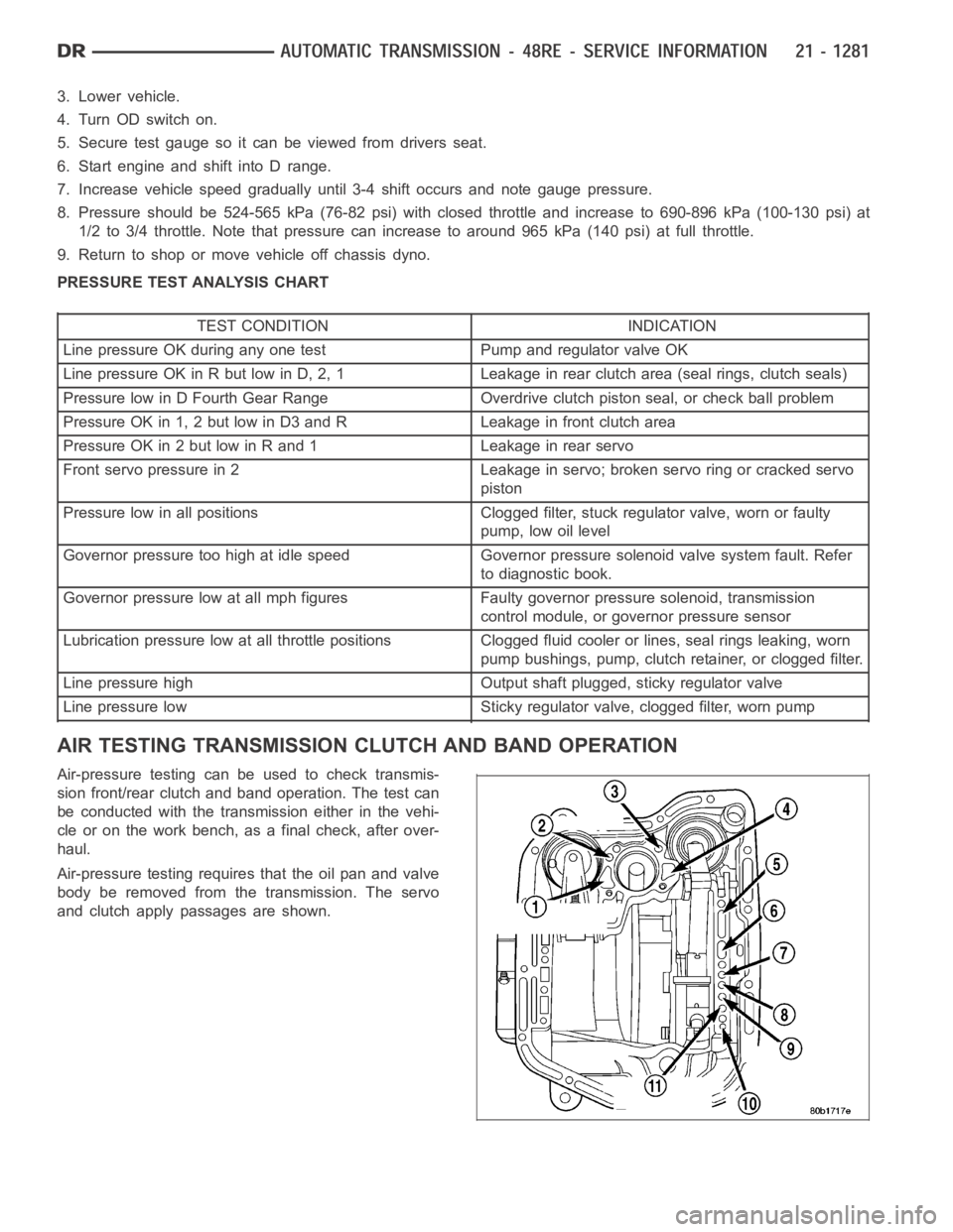
AIR TESTING TRANSMISSION CLUTCH AND BAND OPERATION
Air-pressure testing can be used to check transmis-
sion front/rear clutch and band operation. The test can
be conducted with the transmission either in the vehi-
cle or on the work bench, as a final check, after over-
haul.
Air-pressure testing requires that the oil pan and valve
body be removed from the transmission. The servo
and clutch apply passages are shown.
Page 3805 of 5267
CONDITION POSSIBLE CAUSES CORRECTION
DELAYED ENGAGEMENT
(FROM NEUTRAL TO
DRIVE OR REVERSE)1. Fluid Level Low. 1. Correct level and check for leaks.
2. Filter Clogged. 2. Change filter.
3. Gearshift Linkage Mis-adjusted. 3. Adjust linkage and repair linkage ifworn
or damaged.
4. Torque Converter Drain Back (Oil
drains from torque converter into
transmission sump).4. If vehicle moves normally after 5
seconds after shifting into gear, no repair is
necessary. If longer, inspect pump bushing
for wear. Replace pump house.
5. Rear Band Mis-adjusted. 5. Adjust band.
6. Valve Body Filter Plugged. 6. Replace fluid and filter. If oil pan and old
fluid were full of clutch disc material and/or
metal particles, overhaul will be necessary.
7. Oil Pump Gears Worn/Damaged. 7. Remove transmission and replace oil
pump.
8. Governor Circuit and Solenoid
Valve Electrical Fault.8. Test with DRB
scan tool and repair as
required.
9. Hydraulic Pressure Incorrect. 9. Perform pressure test, remove
transmission and repair as needed.
10. Reaction Shaft Seal Rings
Worn/Broken.10. Remove transmission, remove oil pump
and replace seal rings.
11. Rear Clutch/Input Shaft, Rear
Clutch Seal Rings Damaged.11. Remove and disassemble transmission
and repair as necessary.
12. Regulator Valve Stuck. 12. Clean.
13. Cooler Plugged. 13. Transfer case failure can plug cooler.
NO DRIVE RANGE
(REVERSE OK)1. Fluid Level Low. 1. Add fluid and check for leaks if drive is
restored.
2. Gearshift Linkage/Cable
Loose/Misadjusted.2. Repair or replace linkage components.
3. Rear Clutch Burnt. 3. Removeand disassemble transmission
and rear clutch and seals. Repair/replace
worn or damaged parts as needed.
4. Valve Body Malfunction. 4. Remove and disassemble valve body.
Replace assembly if any valves or bores
are damaged.
5. Transmission Overrunning Clutch
Broken.5. Remove and disassemble transmission.
Replace overrunning clutch.
6. Input Shaft Seal Rings Worn/
Damaged.6. Remove and disassemble transmission.
Replace seal rings and any other worn or
damaged parts.
7. Front Planetary Failed Broken. 7. Remove and repair.