2006 DODGE RAM SRT-10 fuel pump
[x] Cancel search: fuel pumpPage 1219 of 5267
12.FUEL SUPPLY LINE RESTRICTED
Turn the ignition off.
WARNING: The fuel system is under a constant pressure (even with the engineoff). Before testing or ser-
vicing any fuel system hose, fitting or line, the fuel system pressure mustbe released. Failure to follow
these instructions can result in personal injury or death.
Raise vehicle on hoist, and disconnect the fuel pressure line at the fuel pump module.
Install special tool #6539 (5/16
) #6631(3/8) fuel line adapter and the fuel pressure gauge between the fuel supply
line and the fuel pump module.
Ignition on, engine not running.
With the scan tool, actuate the ASD FuelSystem test and observe the fuel pressure gauge.
NOTE: Fuel pressure specification is 379 KPa +/- 14 KPa (55 psi +/- 2 psi).
Is the fuel pressure within specification?
Ye s>>
Repair or replace fuel supply line as necessary.
Perform the POWERTRAIN VERIFICATION TEST. (Refer to 9 - ENGINE - STANDARD PROCEDURE)
No>>
Go To 13
13.FUEL PUMP INLET STRAINER
Turn the ignition off.
WARNING: The fuel system is under a constant pressure (even with the engineoff). Before testing or ser-
vicing any fuel system hose, fitting or line, the fuel system pressure mustbe released. Failure to follow
these instructions can result in personal injury or death.
Remove the Fuel Pump Module and inspect the Fuel Inlet Strainer.
Is the Fuel Inlet Strainer plugged?
Ye s>>
Replace the Fuel Pump Inlet Strainer.
Perform the POWERTRAIN VERIFICATION TEST. (Refer to 9 - ENGINE - STANDARD PROCEDURE)
No>>
Before continuing, check the Fuel Pump Module harness connector terminals for corrosion, damage, or
terminal push out. Make sure the ground circuit is functional. Repair as necessary. Replace the Fuel
Pump Module.
Perform the POWERTRAIN VERIFICATION TEST. (Refer to 9 - ENGINE - STANDARD PROCEDURE)
14.IGNITION WIRE
NOTE: If the vehicle being tested does not have an ignition wire answer YES to this test and continue.
Turn the ignition off.
Remove the ignition wire.
Measure the resistance of the ignition wire.
Is the resistance below 10K ohms?
Ye s>>
Go To 15
No>>
Replace the Ignition Wire.
Perform the POWERTRAIN VERIFICATION TEST. (Refer to 9 - ENGINE - STANDARD PROCEDURE)
Page 1220 of 5267
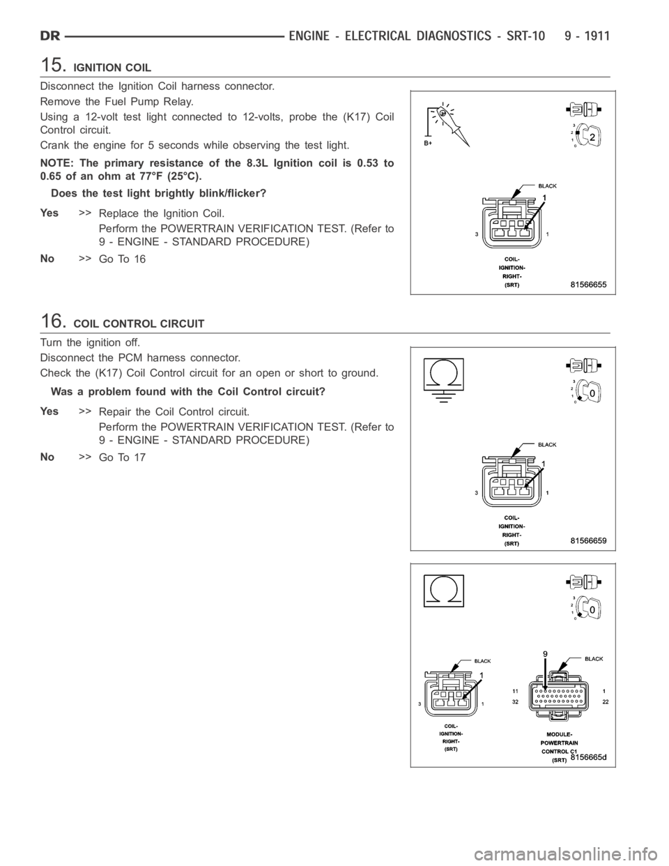
15.IGNITION COIL
Disconnect the Ignition Coil harness connector.
Remove the Fuel Pump Relay.
Using a 12-volt test light connected to 12-volts, probe the (K17) Coil
Control circuit.
Crank the engine for 5 seconds while observing the test light.
NOTE: The primary resistance of the 8.3L Ignition coil is 0.53 to
0.65 of an ohm at 77°F (25°C).
Does the test light brightly blink/flicker?
Ye s>>
Replace the Ignition Coil.
Perform the POWERTRAIN VERIFICATION TEST. (Refer to
9 - ENGINE - STANDARD PROCEDURE)
No>>
Go To 16
16.COIL CONTROL CIRCUIT
Turn the ignition off.
Disconnect the PCM harness connector.
Check the (K17) Coil Control circuit for an open or short to ground.
Was a problem found with the Coil Control circuit?
Ye s>>
Repair the Coil Control circuit.
Perform the POWERTRAIN VERIFICATION TEST. (Refer to
9 - ENGINE - STANDARD PROCEDURE)
No>>
Go To 17
Page 1268 of 5267
When Monitored:
With engine temperature greater than 170° F, fuel control in closed loop, engine idling for 2 minutes, no low
fuel, MAP less than 15.7 inches mercury and barometric altitude less than 8,000 feet.
Set Condition:
After having passed the Leak Detection Pump (LDP) test, no air flow throughthe evaporative system is
detected by the EVAP monitor.
Possible Causes
EVAP PURGE HOSE (SOLENOID TO CANISTER)
EVAP PURGE HOSE (CANISTER TO FUEL TANK)
EVAP PURGE SOLENOID VACUUM SUPPLY
EVAP PURGE SOLENOID (LEAKS/STUCK OPEN)
EVAP PURGE SOLENOID
For the Engine circuit diagram (Refer to 8 - ELECTRICAL/ELECTRONIC CONTROL MODULES/ENGINE CON-
TROL MODULE - SCHEMATIC - ELECTRICAL)
Diagnostic Test
1.VEHICLE HISTORY AND SERVICE BULLETIN INVESTIGATION
Ignition on, engine not running.
With a scan tool, read DTCs and record the related Freeze Frame data if any DTC(s) are present.
Whether or not any DTC(s) are present you will want to check the following items which may assist in repairing the
customer’s complaint successfully.
Check the vehicles repair history.
If the vehicle has a repair history that pertains to the customer’s currentcomplaint, review the repair.
Inspect the vehicle for any aftermarket accessories that may have been installed incorrectly.
Check for any service bulletin(s) related to the customer’s complaint or DTC(s).
If a service bulletin applies, follow the instructions per the service bulletin.
Choose the following scenario that best applies.
The service bulletin repaired the customer’s complaint.
Testing complete.
A DTC is present, no service bulletins apply, or the service bulletin didn’t repair the customer’s complaint.
Go To 2
2.GOOD TRIP EQUAL TO ZERO
Check for any related TSBs.
Ignition on, engine not running.
With the scan tool, read DTCs and record the related Freeze Frame data.
Is the Good Trip Counter displayed and equal to zero?
Ye s>>
Go To 3
No>>
Refer to the INTERMITTENT CONDITION Diagnostic Procedure.
Perform POWERTRAIN VERIFICATION TEST. (Refer to 9 - ENGINE - STANDARD PROCEDURE)
Page 1269 of 5267
3.VISUAL INSPECTION
Visually inspect the Evap canister. Look for any physical damage or any signs of fuel that has entered the canister.
Any signs of fuel may indicate a bad rollover valve.
Were any problems found?
Ye s>>
Repair or Replace as necessary.
Perform POWERTRAIN VERIFICATION TEST. (Refer to 9 - ENGINE - STANDARD PROCEDURE)
No>>
Go To 4
4.VISUAL INSPECTION OF EVAP PURGE HOSE (SOLENOID TO CANISTER)
Visually inspect the Evap purge hose that goes from the Purge Solenoid to the Evap Canister. Look for any physical
damage such as a pinched, plugged, ripped or dry rotted hose.
Were any problems found?
Ye s>>
Repair or replace hose as necessary.
Perform POWERTRAIN VERIFICATION TEST. (Refer to 9 - ENGINE - STANDARD PROCEDURE)
No>>
Go To 5
5.VISUAL INSPECTION OF EVAP PURGE HOSE (EVAP CANISTER TO FUEL TANK)
Visually inspect the Evap Purge hose that goes between the Evap canister and the fuel tank. Look for any physical
damage such as a pinched, plugged, ripped or dry rotted hose.
Were any problems found?
Ye s>>
Repair or replace hose as necessary.
Perform POWERTRAIN VERIFICATION TEST. (Refer to 9 - ENGINE - STANDARD PROCEDURE)
No>>
Go To 6
6.EVAP VACUUM SUPPLY HOSE INSPECTION
Carefully inspect the Evap Purge Solenoid vacuum supply hose for proper routing. Also check for a pinched or
plugged hose from the throttle body to the Purge Solenoid.
Inspect the vacuum nipple at the throttle body for any damage or plugging.
Make sure vacuum fitting at the purge solenoid is not over installed.
Is the vacuum supply hose and throttle body vacuum nipple free from defects?
Ye s>>
Go To 7
No>>
Repair the vacuum supply hose/tube as necessary.
Perform POWERTRAIN VERIFICATION TEST. (Refer to 9 - ENGINE - STANDARD PROCEDURE)
7.EVAP PURGE SOLENOID LEAKS
NOTE: After disconnecting the Evap Purge Solenoid vacuum connections, inspect the lines and solenoid for
any signs of contamination from the EVAP Canister. This may indicate a faulty rollover valve. Replace purge
solenoid if contamination is found
Disconnect the vacuum hoses at the EVAP Purge Solenoid.
Using a hand vacuum pump, apply 10 inches of vacuum to the Evap Purge Solenoid vacuum source port. (com-
ponent side)
Does the Evap Purge Solenoid hold vacuum?
Ye s>>
Go To 8
No>>
Replace the Evap Purge Solenoid and the Evap Canister and clean out Evap lines as necessary.
Perform POWERTRAIN VERIFICATION TEST. (Refer to 9 - ENGINE - STANDARD PROCEDURE)
Page 1276 of 5267
6.LEAK AT GAS CAP
Remove the SMOKE supply tip (black hose) from the service port (if equipped) or to the #8404–ADP adapter.
Install gas cap adapter, Miller Tool #8382 (1/4 turn cap) or #6922 (screw cap) and #8399* (secondary seal depres-
sor) and repeat test 5.
Was a leak found at the gas cap adapter?
Ye s>>
Replace the Fuel Filler tube assembly.
Perform the POWERTRAIN VERIFICATION TEST. (Refer to 9 - ENGINE - STANDARD PROCEDURE)
No>>
Replace the gas cap.
Perform the POWERTRAIN VERIFICATION TEST. (Refer to 9 - ENGINE - STANDARD PROCEDURE)
7.LEAK DETECTION PUMP
Apply an external vacuum to the LDP.
Using a scan tool, close the LDP seal to atmosphere.
Inject smoke into the Evap system using the EELD.
Examine the LDP filter port for smoke.
Is smoke visible from the LDP?
Ye s>>
Replace the Leak Detection Pump.
Perform the POWERTRAIN VERIFICATION TEST. (Refer to 9 - ENGINE - STANDARD PROCEDURE)
No>>
Go To 8
8.EVAP PURGE SOLENOID OPERATION
To continue testing you will need Miller Tool #8404 Evaporative Emission Leak Detector (EELD).
Connect the red power lead of the EELD to the battery positive terminal and the black ground lead to the battery
negative ternal.
Disconnect the vacuum hoses at the Evap Purge Solenoid.
Connect the SMOKE supply tip (black hose) to the service port (if equipped)or to the #8404-ADP adapter.
Set the smoke/air control switch to SMOKE.
Press the remote smoke/air start button.
NOTE: Below is an optional method of checking the purge valve for leaks if the EELD is unavailable.
Turn the ignition off.
Disconnect the vacuum hoses at the Evap Purge Solenoid.
Using a hand vacuum pump, apply 10 in Hg to the
CANof the EVAP Purge Solenoid.
With the scan tool, actuate the Evap Purge Solenoid.
NOTE: If the Evap Purge Solenoid does not hold a vacuum, it will need to be repalced..
Is smoke visible from the Evap Purge Solenoid?
Ye s>>
Replace the Evap Purge Solenoid.
Perform the POWERTRAIN VERIFICATION TEST. (Refer to 9 - ENGINE - STANDARD PROCEDURE)
No>>
Te s t C o m p l e t e .
Page 1286 of 5267
6.LEAK AT GAS CAP
Remove the SMOKE supply tip (black hose) from the service port (if equipped) or to the #8404–ADP adapter.
Install gas cap adapter, Miller Tool #8382 (1/4 turn cap) or #6922 (screw cap) and #8399* (secondary seal depres-
sor) and repeat test 5.
Was a leak found at the gas cap adapter?
Ye s>>
Replace the Fuel Filler tube assembly.
Perform the POWERTRAIN VERIFICATION TEST. (Refer to 9 - ENGINE - STANDARD PROCEDURE)
No>>
Replace the gas cap.
Perform the POWERTRAIN VERIFICATION TEST. (Refer to 9 - ENGINE - STANDARD PROCEDURE)
7.LEAK DETECTION PUMP
Apply an external vacuum to the LDP.
Using a scan tool, close the LDP seal to atmosphere.
Inject smoke into the Evap system using the EELD.
Examine the LDP filter port for smoke.
Is smoke visible from the LDP?
Ye s>>
Replace the Leak Detection Pump.
Perform the POWERTRAIN VERIFICATION TEST. (Refer to 9 - ENGINE - STANDARD PROCEDURE)
No>>
Go To 8
8.EVAP PURGE SOLENOID OPERATION
To continue testing you will need Miller Tool #8404 Evaporative Emission Leak Detector (EELD).
Connect the red power lead of the EELD to the battery positive terminal and the black ground lead to the battery
negative ternal.
Disconnect the vacuum hoses at the Evap Purge Solenoid.
Connect the SMOKE supply tip (black hose) to the service port (if equipped)or to the #8404-ADP adapter.
Set the smoke/air control switch to SMOKE.
Press the remote smoke/air start button.
NOTE: Below is an optional method of checking the purge valve for leaks if the EELD is unavailable.
Turn the ignition off.
Disconnect the vacuum hoses at the Evap Purge Solenoid.
Using a hand vacuum pump, apply 10 in Hg to the
CANof the EVAP Purge Solenoid.
With the scan tool, actuate the Evap Purge Solenoid.
NOTE: If the Evap Purge Solenoid does not hold a vacuum, it will need to be repalced..
Is smoke visible from the Evap Purge Solenoid?
Ye s>>
Replace the Evap Purge Solenoid.
Perform the POWERTRAIN VERIFICATION TEST. (Refer to 9 - ENGINE - STANDARD PROCEDURE)
No>>
Te s t C o m p l e t e .
Page 1287 of 5267
P0460-FUEL LEVEL SENDING UNIT NO CHANGE OVER MILES
For a complete wiring diagramRefer to Section 8W.
When Monitored:
Engine running and fuel level either below 15% or above 85% of capacity.
Set Condition:
The PCM sees low fuel, less than 15%, for more than 120 miles or fuel level does not change by at least 4%
for more than 250 miles.
Possible Causes
PHYSICALLY DAMAGED/DEFORMED/OBSTRUCTED FUEL TANK
FUEL LEVEL SENSOR
Always perform the Pre-Diagnostic Troubleshooting procedure before proceeding. (Refer to 9 - ENGINE -
DIAGNOSIS AND TESTING)
1.CHECKING FOR A DAMAGED/DEFORMED/OBSTRUCTED FUEL TANK
Turn the ignition off.
WARNING: WARNING: The fuel system is under a constant pressure, even with the engine off. Before test-
ing or servicing any fuel system hose, fitting or line, the fuel system pressure must be released.
Inspect the outside of the fuel tank for defects.
Remove the fuel tank.
Remove the fuel pump module from the fuel tank.
Inspect the inside of the fuel tank for any obstructions or deformities.
Is the fuel tank free from defects?
Ye s>>
Go To 2
No>>
Repair or replace the fuel tank as necessary.
Perform POWERTRAIN VERIFICATION TEST. (Refer to 9 - ENGINE - STANDARD PROCEDURE)
2.FUEL LEVEL SENSOR
If there are no possible causes remaining, view repair.
Repair
Replace the Fuel Level Sensor.
Perform POWERTRAIN VERIFICATION TEST. (Refer to 9 - ENGINE - STANDARD PROCEDURE)
Page 1289 of 5267
When Monitored:
Ignition on and battery voltage above 10.4 volts.
Set Condition:
The fuel level sensor signal voltage goes below 0.4 of a volt for more than 90seconds. One Trip Fault. Three
good trips to turn off the MIL.
Possible Causes
(N4) FUEL LEVEL SIGNAL CIRCUIT SHORTED TO GROUND
(N4) FUEL LEVEL SIGNAL CIRCUIT SHORTED TO THE (K900) SENSOR GROUND CIRCUIT
FUEL LEVEL SENSOR
INSTRUMENT CLUSTER
Always perform the Pre-Diagnostic Troubleshooting procedure before proceeding. (Refer to 9 - ENGINE -
SCHEMATICS AND DIAGRAMS).
Diagnostic Test
1.FUEL LEVEL SENSOR VOLTAGE BELOW 0.4 OF A VOLT
NOTE: Diagnose any Bus Message failures before continuing.
Ignition on, engine not running.
With the scan tool, read the Fuel Level Sensor voltage.
Is the Fuel Level Sensor voltage below 0.4 of a volt?
Ye s>>
Go To 2
No>>
Refer to the INTERMITTENT CONDITION Diagnostic Procedure.
Perform the POWERTRAIN VERIFICATION TEST. (Refer to 9 - ENGINE - STANDARD PROCEDURE)
2.FUEL LEVEL SENSOR
Turn the ignition off.
Disconnect the Fuel Pump Module harness connector.
Ignition on, engine not running.
With the scan tool, read the Fuel Level Sensor voltage.
Did the Fuel Level Sensor voltage change from below 0.4 of a volt to above 4.0volts?
Ye s>>
Replace the Fuel Level Sensor.
Perform the POWERTRAIN VERIFICATION TEST. (Refer to 9 - ENGINE - STANDARD PROCEDURE)
No>>
Go To 3