Page 4291 of 5267
6. Install snap-ring (2).
7. Align and install low range/input gear assembly (2)
in front case (1). Be sure low range gear pinions
are engaged in annulus gear and that input gear
shaft is fully seated in front bearing.
8. Install snap-ring (2) to hold input/low range gear (1)
into front bearing.
9. Install a new input gear oil seal with Seal Installer
9036 and Universal Handle C-4171.
Page 4298 of 5267
10. Insert magnet (1) in front case pocket (2).
REAR CASE
1. Install the oil pick-up tube and screen into the rear
case half.
2. Apply bead of Mopar
Gasket Maker, or equivalent,
to mating surface of front case. Keep sealer bead
width to maximum of 3/16 inch. Do not use exces-
sive amount of sealer as excess will be displaced
into case interior.
3. Align mainshaft with the rear output shaft bearing
and align shift rail with bore in rear case. Then
install rear case (2). Verify that the case alignment
dowels correctly seat into their mating recesses.
4. Install 4-5 rear case (2) to front case (1) bolts (3) to
hold rear case in position. Tighten bolts snug but
not to specified torque at this time.
CAUTION: Verify that shift rail, and case alignment
dowels are seated before installing any bolts.
Case could be cracked if shaft rail or dowels are
misaligned.
5. Tighten bolts to 27-34 Nꞏm (20-25 ft. lbs.).
Page 4299 of 5267
6. Install rear output bearing inner snap-ring (3) to
output shaft (1).
OIL PUMP AND REAR EXTENSION
1. Install the oil pump (3) onto the output shaft (2).
Page 4300 of 5267
2. Engage the oil pump pick-up tube (2) into the oil
pump (1). Verify that the pick-up tube o-ring is on
the tube and is correctly installed to the oil pump.
3. Apply bead of Mopar
Gasket Maker, or equivalent,
to mating surface of rear extension housing. Keep
sealer bead width to maximum of 3/16 inch. Do not
use excessive amount of sealer as excess could
be displaced into output bearing.
4. Install extension housing (2) onto the rear case half
(1).
5. Install rear extension bolts (2). Tighten the bolts to
27-34 Nꞏm (20-25 ft.lbs.).
Page 4326 of 5267

STANDARD PROCEDURE
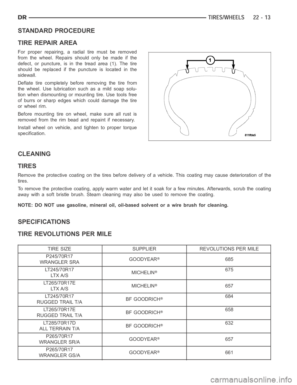
TIRE REPAIR AREA
For proper repairing, a radial tire must be removed
from the wheel. Repairs should only be made if the
defect, or puncture, is in the tread area (1). The tire
should be replaced if the puncture is located in the
sidewall.
Deflate tire completely before removing the tire from
the wheel. Use lubrication such as a mild soap solu-
tion when dismounting or mounting tire. Use tools free
of burrs or sharp edges which could damage the tire
or wheel rim.
Before mounting tire on wheel, make sure all rust is
removed from the rim bead and repaint if necessary.
Install wheel on vehicle, and tighten to proper torque
specification.
CLEANING
TIRES
Remove the protective coating on the tires before delivery of a vehicle. This coating may cause deterioration of the
tires.
To remove the protective coating, apply warm water and let it soak for a few minutes. Afterwards, scrub the coating
away with a soft bristle brush. Steam cleaning may also be used to remove thecoating.
NOTE: DO NOT use gasoline, mineral oil, oil-based solvent or a wire brush for cleaning.
SPECIFICATIONS
TIRE REVOLUTIONS PER MILE
TIRE SIZE SUPPLIER REVOLUTIONS PER MILE
P245/70R17
WRANGLER SRAGOODYEAR
685
LT245/70R17
LT X A / SMICHELIN
675
LT265/70R17E
LT X A / SMICHELIN
657
LT245/70R17
RUGGED TRAIL T/ABF GOODRICH
684
LT265/70R17E
RUGGED TRAIL T/ABF GOODRICH
658
LT285/70R17D
ALL TERRAIN T/ABF GOODRICH
632
P265/70R17
WRANGLER SR/AGOODYEAR
657
P265/70R17
WRANGLER GS/AGOODYEAR
661
Page 4330 of 5267
NOTE: Do not use chrome plated lug nuts with
chrome plated wheels.
NOTE: All wheel nuts should then be tightened
just snug. Gradually tighten them in sequence to
the proper torque specification.
NOTE: Never use oil or grease on studs or nuts.
Before installing the wheel, be sure to remove any
build up of corrosion on the wheel mounting surfaces.
Ensure wheels are installed with good metal-to-metal
contact. Improper installation could cause loosening of
wheel nuts. This could affect the safety and handling
of your vehicle.
To install the wheel (3), first position it properly on the mounting surface.
8–lug.
(SRT10).
Page 4331 of 5267

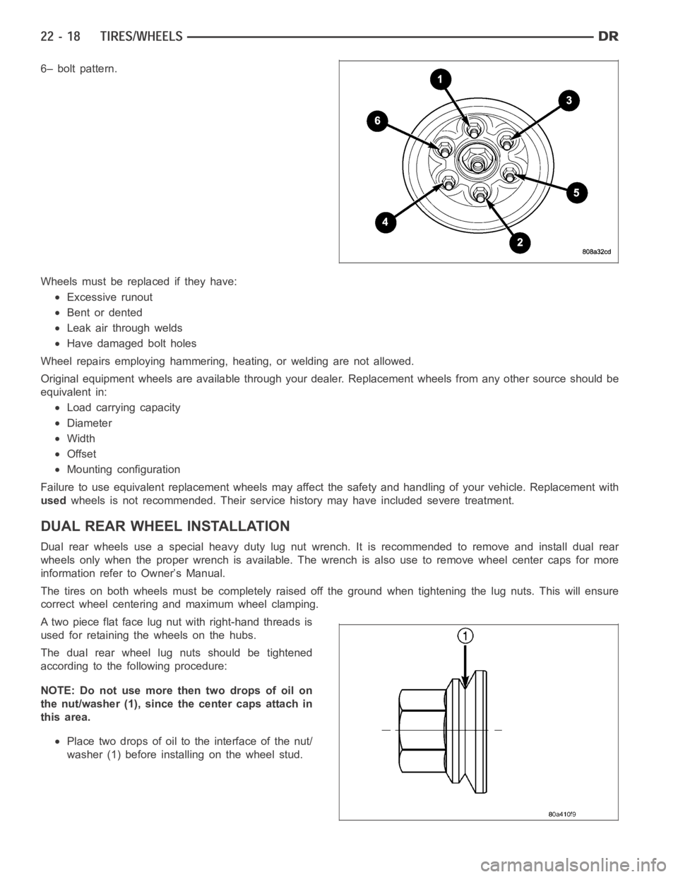
6– bolt pattern.
Wheels must be replaced if they have:
Excessive runout
Bent or dented
Leak air through welds
Have damaged bolt holes
Wheel repairs employing hammering, heating, or welding are not allowed.
Original equipment wheels are available through your dealer. Replacement wheels from any other source should be
equivalent in:
Load carrying capacity
Diameter
Width
Offset
Mounting configuration
Failure to use equivalent replacement wheels may affect the safety and handling of your vehicle. Replacement with
usedwheels is not recommended. Their service history may have included severetreatment.
DUAL REAR WHEELINSTALLATION
Dual rear wheels use a special heavy duty lug nut wrench. It is recommended to remove and install dual rear
wheels only when the proper wrench is available. The wrench is also use to remove wheel center caps for more
information refer to Owner’s Manual.
The tires on both wheels must be completely raised off the ground when tightening the lug nuts. This will ensure
correct wheel centering and maximum wheel clamping.
A two piece flat face lug nut with right-hand threads is
used for retaining the wheels on the hubs.
The dual rear wheel lug nuts should be tightened
according to the following procedure:
NOTE: Do not use more then two drops of oil on
the nut/washer (1), since the center caps attach in
this area.
Place two drops of oil to the interface of the nut/
washer (1) before installing on the wheel stud.
Page 4341 of 5267

POSSIBLE CAUSE OF WIND NOISE
Moldings standing away from body surface can catch wind and whistle.
Gaps in sealed areas behind overhanging body flanges can cause wind-rushing sounds.
Misaligned movable components.
Missing or improperly installed plugs in pillars.
Weld burn through holes.
Improperly installed roof rack cross bars.
STANDARD PROCEDURE
BODY LUBRICATION
All mechanisms and linkages should be lubricated when necessary. This will maintain ease of operation and provide
protection against rust and excessive wear. The weatherstrip seals should be lubricated to prolong their life as well
as to improve door sealing.
All applicable exterior and interior vehicle operating mechanisms should be inspected and cleaned. Pivot/sliding con-
tact areas on the mechanisms should then be lubricated.
1. When necessary, lubricate the operating mechanisms with the specifiedlubricants.
2. Apply silicone lubricant to a clothand wipe it on door seals to avoid over-spray that can soil passenger’s cloth-
ing.
3. Before applying lubricant, the component should be wiped clean. After lubrication, any excess lubricant should be
removed.
4. The hood latch, latch release mechanism, latch striker, and safety latch should be lubricated periodically.
5. The door lock cylinders should be lubricated twice each year (preferably autumn and spring).
Spray a small amount of lock cylinder lubricant directly into the lock cylinder.
Apply a small amount to the key and insert it into the lock cylinder.
Rotate it to the locked position and then back to the unlocked position several times.
Remove the key. Wipe the lubricant from it with a clean cloth to avoid soiling of clothing.
HEAT STAKING
1. Remove trim panel.
2. Bend or move the trim panel components at the heat staked joints. Observethe heat staked locations and/or
component seams for looseness.
3. Heat stake the components.
a. If the heat staked or component seam location is loose, hold the two components tightly together and using
a soldering gun with a flat tip, melt the material securing the components together. Do not over heat the
affected area, damage to the exterior of the trim panel may occur.
b. Iftheheatstakedmaterialisbrokenormissing,useahotglueguntoapplynewmaterialtotheareatobe
repaired. The panels that are being heat staked must be held together whiletheapplyingtheglue.Oncethe
new material is in place, it may be necessary to use a soldering gun to melt the newly applied material. Do
not over heat the affected area, damage to the exterior of the trim panel mayoccur.
4. Allow the repaired area to cool and verify the repair.
5. Install trim panel.
BUZZ, SQUEAK & RATTLE
Buzz, Squeak & Rattles (BSR) may be caused by any one or more of the followingand may be corrected as indi-
cated:
Loose fasteners should be tightened to specifications.
Damaged or missing clips should be replaced.
Damaged trim panels should be replaced.
Incorrectly installed trim panels should be reinstalled properly.