2006 DODGE RAM SRT-10 oil
[x] Cancel search: oilPage 4669 of 5267
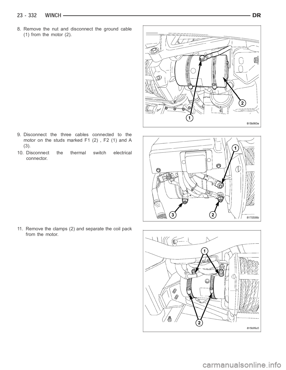
8. Remove the nut and disconnect the ground cable
(1) from the motor (2).
9. Disconnect the three cables connected to the
motor on the studs marked F1 (2) , F2 (1) and A
(3).
10. Disconnect the thermal switch electrical
connector.
11. Remove the clamps (2) and separate the coil pack
from the motor.
Page 5053 of 5267
ACTUATOR DTC DETECTION TEST — DUAL-ZONE
The Actuator DTC Detection Test:
is actuated with a scan tool.
clears all actuator related DTCs when the test is actuated.
supplements the continuous diagnostics on the actuator drive system.
monitors for shorted actuator circuits allowing service to easily diagnose and troubleshoot up to three simul-
taneous shorts. Shorted actuator circuit faults (XXX Control Circuit High or XXX Control Circuit Low) will only
display after running the Actuator DTC Detection Test.
After repairing each DTC, cycle the ignition switch, and then run the Actuator DTC Detection Test again to ensure
that no new DTCs exist. If multiple DTCs are present, beginning with the passenger blend door, diagnose and repair
all short high faults and then short low faults. When the test returns passed, clear all faults and run the Actuator
Calibration function as a final check of system health.
ACTUATOR DTC DETECTION TEST — SINGLE-ZONE
The Actuator DTC Detection Test:
is actuated with a scan tool.
clears all actuator related DTCs when the test is actuated.
supplements the continuous diagnostics on the actuator drive system.
monitors for shorted actuator circuits allowing service to easily diagnose and troubleshoot up to three simul-
taneous shorts. Shorted actuator circuit faults (XXX Control Circuit High or XXX Control Circuit Low) will only
display after running the Actuator DTC Detection Test.
After repairing each DTC, cycle the ignition switch, and then run the Actuator DTC Detection Test again to ensure
that no new DTCs exist. If multiple DTCs are present, beginning with the common circuit, diagnose and repair all
short high faults and then short low faults. When the test returns passed, clear all faults and run the Actuator Cal-
ibration function as a final check of system health.
A/C PERFORMANCE
The A/C system is designed to provide the passenger compartment with low temperature and low humidity air. The
A/C evaporator, located in the HVAC housing is cooled to temperatures nearthe freezing point. As warm damp air
passes over the fins of the A/C evaporator, the air transfers its heat to therefrigerant in the evaporator coils and the
moisture in the air condenses on the evaporator fins. During periods of high heat and humidity, an A/C system will
be more effective in the Recirculation mode (max-A/C). With the system in the Recirculation mode, only air from the
passenger compartment passes through the A/C evaporator. As the passenger compartment air dehumidifies, the
A/C system performance levels rise.
Humidity has an important bearing on the temperature of the air delivered to the interior of the vehicle. It is impor-
tant to understand the effect that humidity has on the performance of the A/C system. When humidity is high, the
A/C evaporator has to perform a double duty. It must lower the air temperature, and it must lower the temperature
of the moisture in the air that condenses on the evaporator fins. Condensing the moisture in the air transfers heat
energy into the evaporator fins and coils. This reduces the amount of heat the A/C evaporator can absorb from the
air. High humidity greatly reduces the ability of the A/C evaporator to lower the temperature of the air.
However, evaporator capacity used to reduce the amount of moisture in the air is not wasted. Wringing some of the
moisture out of the air entering the vehicle adds to the comfort of the passengers. Although, an owner may expect
too much from their A/C system on humid days. A performance test is the best way to determine whether the sys-
tem is performing up to design standards. This test also provides valuableclues as to the possible cause of trouble
with the A/C system. The ambient air temperature in the location where the vehicle will be tested must be a mini-
mum of 21° C (70° F) for this test.
A/C PERFORMANCE TEST
WARNING: Refer to the applicable warnings and cautions for this system before performing the following
operation (Refer to 24 - HEATING & AIR CONDITIONING/PLUMBING - WARNINGS) and (Refer to 24 - HEAT-
ING & AIR CONDITIONING/PLUMBING - CAUTIONS). Failure to follow the warnings and cautions could result
in possible personal injury or death.
Page 5055 of 5267
Condition Possible Causes Correction
2. Faulty fuse.2. Check the fuse in the junction block. Repair the
shorted circuit or component and replace the fuse,
if required.
3. Faulty A/C compressor
clutch field coil.3. See A/C Compressor Clutch Field Coil in this
group. Test the compressor clutch field coil and
replace, if required.
4. Improperly installed or
faulty Evaporator
Temperature Sensor.4. See Evaporator Temperature Sensor in this
group. Correctly install or replace the sensor as
required.
5. Faulty A/C pressure
transducer.5. See A/C pressure transducer in this group. Test
the transducer and replace, if required.
6. Faulty A/C-heater control,
totally integrated power
module (TIPM), gateway
module or PCM/ECM.6. Refer to the appropriate Electrical Diagnostic
Procedures for testing of the A/C-heater control,
TIPM, gateway module or PCM/ECM. Test the
module and replace, if required.
Normal pressures, but A/C
Performance Test air
temperatures at center panel
outlet are too high.1. Excessive refrigerant oil in
system.1. See Refrigerant Oil Level in this group. Recover
the refrigerant from the refrigerant system and
inspect the refrigerant oil content. Restore the
refrigerant oil to the proper level, if required.
2. Blend door inoperative or
sealing improperly.2. See Blend Door in this group. Inspect the blend
door for proper operation and sealing and correct,
if required.
3. Blend door actuator faulty
or inoperative.3. Perform blend door actuator diagnosis, replace
if faulty.
The low side pressure is
normal or slightly low, and
the high side pressure is too
low.1. Low refrigerant system
charge.1. See Refrigerant System Leaks in this group.
Test the refrigerant system for leaks. Repair,
evacuate and charge the refrigerant system, if
required.
2. Refrigerant flow through
the accumulator is restricted.2. See Accumulator in this group. Replace the
restricted accumulator, if required.
3. Refrigerant flow through
the evaporator coil is
restricted.3. See A/C Evaporator in this group. Replace the
restricted evaporator coil, if required.
4. Faulty compressor.4. See A/C Compressor in this group. Replace the
compressor, if required.
The low side pressure is
normal or slightly high, and
the high side pressure is too
high.1. Condenser air flow
restricted.1. Check the A/C condenser for damaged fins,
foreign objects obstructing air flow through the
condenser fins, and missing or improperly
installed air seals. Refer to Cooling for more
information on air seals. Clean, repair, or replace
components as required.
2. Inoperative cooling fan.2. Refer to Cooling for more information. Test the
cooling fan and replace, if required.
3. Refrigerant system
overcharged.3. See Refrigerant System Charge in this group.
Recover the refrigerant from the refrigerant
system. Charge the refrigerant system to the
proper level, if required.
4. Air in the refrigerant
system.4. See Refrigerant System Leaks in this group.
Test the refrigerant system for leaks. Repair,
evacuate and charge the refrigerant system, if
required.
Page 5057 of 5267
Improper heater hose routing.
Plugged heater hoses or supply and return ports at the cooling system connections.
Plugged heater core.
If proper coolant flow through the cooling system is verified, and heater outlet air temperature is low, a mechanical
problem may exist.
MECHANICAL PROBLEMS
Possible locations or causes of insufficient heat due to mechanical problems are as follows:
Obstructed cowl air intake.
Obstructed heater system outlets.
Blend-air door(s) or actuator(s) not functioning properly.
Faulty blower motor system
Faulty A/C-heater control
TEMPERATURE CONTROL
If the heater outlet air temperature cannot be adjusted with the temperature control on the A/C-heater control, the
following could require service:
Faulty A/C-heater control.
Faulty blend door actuator(s).
Faulty, obstructed or improperly installed blend-air door.
Faulty related wiring harness or connectors.
Improper engine coolant temperature.
SPECIFICATIONS
A/C SYSTEM
Item Description Notes
A/C Compressor Denso 10S17 (3.7L/4.7L/5.7L/8.3L
engines)ND-8 PAG oil
Visteon HS-18 (5.9L engine) VC-46 PAG oil
Freeze–up Control Evaporator Temperature Sensor A/C evaporator mounted
High psi Control A/C pressure transducer A/C discharge line mounted
Refrigerant Charge Capacity Refer to the A/C Underhood
Specification Label located in the
engine compartment.R134a refrigerant
A/C Clutch Field Coil Draw 3.2 - 3.3 amps @ 12V ± 0.5V @
21° C (70° F)3.7L/4.7L/5.7L/8.3L engines
3.1 - 4 amps @ 12V ± 0.5V @ 21°
C(70°F)5.9L engine
A/C Clutch Air Gap 0.35 - 0.60 mm (0.014 - 0.024 in.) 3.7L/4.7L/5.7L/8.3L engines
0.35 - 0.75 mm (0.014 - 0.030 in.) 5.9L engine
TORQUE
Page 5059 of 5267
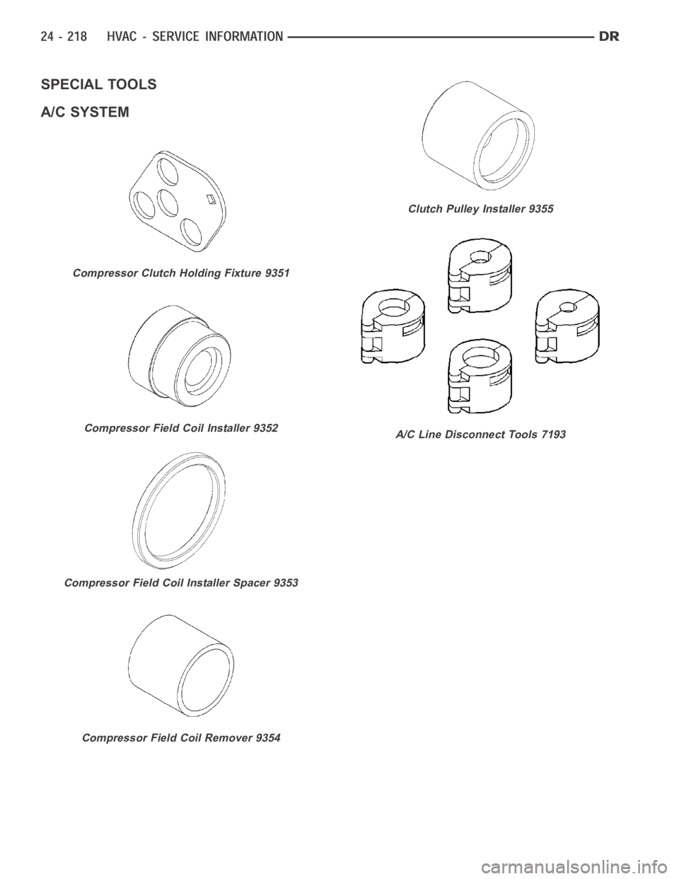
SPECIAL TOOLS
A/C SYSTEM
Compressor Clutch Holding Fixture 9351
Compressor Field Coil Installer 9352
Compressor Field CoilInstaller Spacer 9353
Compressor Field Coil Remover 9354
Clutch Pulley Installer 9355
A/C Line Disconnect Tools 7193
Page 5060 of 5267
page page
ACTUATOR-BLEND DOOR
DESCRIPTION ............................... 220
OPERATION ................................. 220
REMOVAL ................................... 221
INSTALLATION .............................. 222
ACTUATOR-MODE DOOR
DESCRIPTION ............................... 225
OPERATION ................................. 225
REMOVAL ................................... 226
INSTALLATION .............................. 227
ACTUATOR-RECIRCULATION DOOR
DESCRIPTION ............................... 229
OPERATION ................................. 229
REMOVAL ................................... 230
INSTALLATION .............................. 230
CLUTCH-A/C COMPRESSOR
DESCRIPTION ............................... 232
OPERATION ................................. 232
DIAGNOSIS AND TESTING
A/C COMPRESSOR CLUTCH COIL.......... 232
STANDARD PROCEDURE
A/C CLUTCH PLATE INSPECTION.......... 233
A/C CLUTCH BREAK-IN.................... 233
REMOVAL
DENSO A/C COMPRESSOR ................ 234
VISTEON A/C COMPRESSOR .............. 235INSTALLATION
DENSO A/C COMPRESSOR................ 238
VISTEON A/C COMPRESSOR.............. 240
CONTROL-A/C HEATER
DESCRIPTION
MANUAL SINGLE ZONE .................... 243
MANUAL DUAL ZONE ...................... 243
REMOVAL ................................... 244
INSTALLATION .............................. 244
RESISTOR-BLOWER MOTOR
DESCRIPTION ............................... 245
OPERATION ................................. 245
DIAGNOSIS AND TESTING
BLOWER MOTOR RESISTOR ............... 245
REMOVAL ................................... 246
INSTALLATION .............................. 247
SENSOR-EVAPORATOR TEMPERATURE
DESCRIPTION ............................... 248
OPERATION ................................. 248
REMOVAL ................................... 249
INSTALLATION .............................. 250
TRANSDUCER-A/C PRESSURE
DESCRIPTION ............................... 251
OPERATION ................................. 251
REMOVAL ................................... 251
INSTALLATION .............................. 252
Page 5073 of 5267
CLUTCH-A/C COMPRESSOR
DESCRIPTION
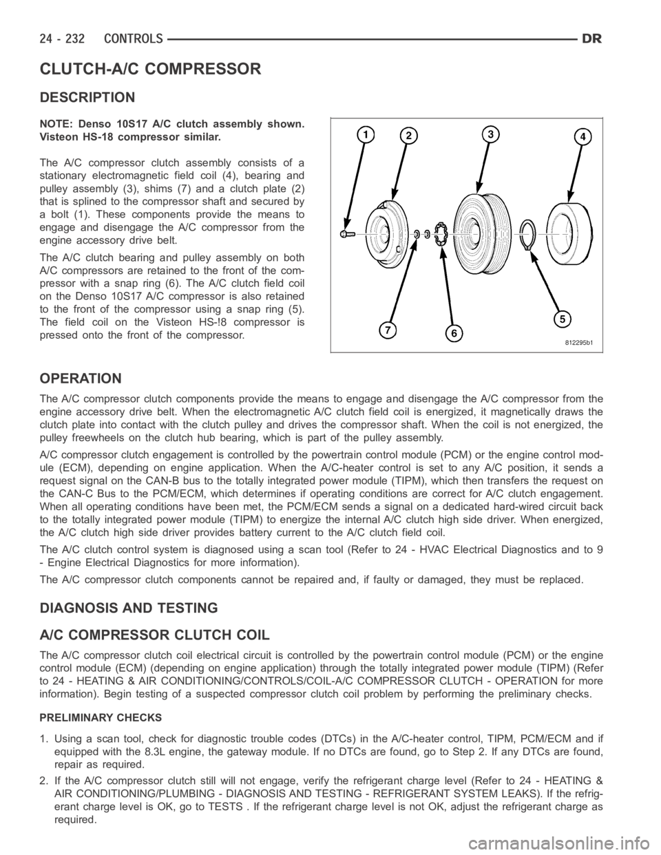
NOTE: Denso 10S17 A/C clutch assembly shown.
Visteon HS-18 compressor similar.
The A/C compressor clutch assembly consists of a
stationary electromagnetic field coil (4), bearing and
pulley assembly (3), shims (7) and a clutch plate (2)
that is splined to the compressor shaft and secured by
a bolt (1). These components provide the means to
engage and disengage the A/C compressor from the
engine accessory drive belt.
The A/C clutch bearing and pulley assembly on both
A/C compressors are retained to the front of the com-
pressor with a snap ring (6). The A/C clutch field coil
on the Denso 10S17 A/C compressor is also retained
to the front of the compressor using a snap ring (5).
The field coil on the Visteon HS-!8 compressor is
pressed onto the front of the compressor.
OPERATION
The A/C compressor clutch components provide the means to engage and disengage the A/C compressor from the
engine accessory drive belt. When the electromagnetic A/C clutch field coil is energized, it magnetically draws the
clutch plate into contact with the clutch pulley and drives the compressorshaft. When the coil is not energized, the
pulley freewheels on the clutch hub bearing, which is part of the pulley assembly.
A/C compressor clutch engagement is controlled by the powertrain controlmodule (PCM) or the engine control mod-
ule (ECM), depending on engine application. When the A/C-heater control is set to any A/C position, it sends a
request signal on the CAN-B bus to the totally integrated power module (TIPM), which then transfers the request on
the CAN-C Bus to the PCM/ECM, which determines if operating conditions arecorrect for A/C clutch engagement.
When all operating conditions have been met, the PCM/ECM sends a signal on adedicated hard-wired circuit back
to the totally integrated power module (TIPM) to energize the internal A/Cclutch high side driver. When energized,
the A/C clutch high side driver provides battery current to the A/C clutch field coil.
The A/C clutch control system is diagnosed using a scan tool (Refer to 24 - HVAC Electrical Diagnostics and to 9
- Engine Electrical Diagnostics for more information).
The A/C compressor clutch components cannot be repaired and, if faulty or damaged, they must be replaced.
DIAGNOSIS AND TESTING
A/CCOMPRESSORCLUTCHCOIL
The A/C compressor clutch coil electrical circuit is controlled by the powertrain control module (PCM) or the engine
control module (ECM) (depending on engine application) through the totally integrated power module (TIPM) (Refer
to 24 - HEATING & AIR CONDITIONING/CONTROLS/COIL-A/C COMPRESSOR CLUTCH -OPERATION for more
information). Begin testing of a suspected compressor clutch coil problem by performing the preliminary checks.
PRELIMINARY CHECKS
1. Using a scan tool, check for diagnostic trouble codes (DTCs) in the A/C-heater control, TIPM, PCM/ECM and if
equipped with the 8.3L engine, the gateway module. If no DTCs are found, go to Step 2. If any DTCs are found,
repair as required.
2. If the A/C compressor clutch still will not engage, verify the refrigerant charge level (Refer to 24 - HEATING &
AIR CONDITIONING/PLUMBING - DIAGNOSIS AND TESTING - REFRIGERANT SYSTEM LEAKS). If the refrig-
erant charge level is OK, go to TESTS . If the refrigerant charge level is notOK, adjust the refrigerant charge as
required.
Page 5074 of 5267
TESTS
1. Verify the battery state of charge (Refer to 8 - ELECTRICAL/BATTERY SYSTEM/BATTERY - DIAGNOSIS AND
TESTING).
2. Connect an ammeter (0 to 10 ampere scale selected) in series with the clutch coil feed terminal. Connect a
voltmeter (0 to 20 volt scale selected) to measure voltage across the battery and the clutch coil.
3. With the A/C-heater control in the A/C mode and the blower motor at low speed, start the engine and allow it to
run at a normal idle speed.
4. The A/C compressor clutch should engage immediately, and the clutch coil supply voltage should be within two
volts of the battery voltage. If the coil supply voltage is OK, go to Step 5. If the coil supply voltage is not within
two volts of battery voltage, test the clutch coil feed circuit for excessive voltage drop and repair as necessary.
5. For the acceptable A/C clutch coil current draw specifications refer to24 - HEATING & AIR CONDITIONING -
SPECIFICATIONS. Specifications apply for a work area temperature of 21° C(70° F). If voltage is more than
12.5 volts, add electrical loads by turning on electrical accessories until voltage reads below 12.5 volts.
STANDARD PROCEDURE
A/C CLUTCH PLATE INSPECTION
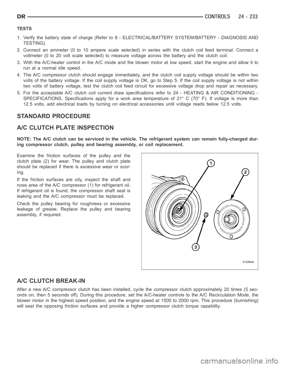
NOTE: The A/C clutch can be serviced inthe vehicle. The refrigerant systemcan remain fully-charged dur-
ing compressor clutch, pulley and bearing assembly, or coil replacement.
Examine the friction surfaces of the pulley and the
clutch plate (2) for wear. The pulley and clutch plate
should be replaced if there is excessive wear or scor-
ing.
If the friction surfaces are oily, inspect the shaft and
nose area of the A/C compressor (1) for refrigerant oil.
If refrigerant oil is found, the compressor shaft seal is
leaking and the A/C compressor must be replaced.
Check the pulley bearing for roughness or excessive
leakage of grease. Replace the pulley and bearing
assembly, if required.
A/C CLUTCH BREAK-IN
After a new A/C compressor clutch hasbeen installed, cycle the compressorclutch approximately 20 times (5 sec-
onds on, then 5 seconds off). During this procedure, set the A/C-heater controls to the A/C Recirculation Mode, the
blower motor in the highest speed position, and the engine speed at 1500 to 2000 rpm. This procedure (burnishing)
will seat the opposing friction surfaces and provide a higher compressor clutch torque capability.