2006 DODGE RAM SRT-10 check engine
[x] Cancel search: check enginePage 3256 of 5267
When Monitored:
Continuously with the ignition on and engine running.
Set Condition:
This DTC is set if the UD pressure switch is in the wrong state for the currentgear. For example, this code
would be set if the UD pressure switch remained off while the transmission was in second gear.
Possible Causes
RELATED TCM POWER INPUT DTCS PRESENT
LOW FLUID LEVEL
NO. 2 CHECK BALL CUT OR DAMAGED
LOW LINE PRESSURE
CRACKED OR MIS-INSTALLED SUMP FILTER OR SEAL
STICKING MAIN REGULATOR VALVE IN PUMP VALVE BODY
(T29) UD PRESSURE SWITCH SENSE CIRCUIT OPEN
(T29) UD PRESSURE SWITCH CIRCUIT SHORT TO GROUND
(T29) UD PRESSURE SWITCH SENSE CIRCUIT SHORT TO ANOTHER CIRCUITS
TRANSMISSION SOLENOID/TRS ASSEMBLY
POWERTRAIN CONTROL MODULE
Always perform the 45RFE/545RFE Pre-Diagnostic Troubleshooting Procedure before proceeding. (Refer to
21 - TRANSMISSION/TRANSAXLE/AUTOMATIC - 45RFE/545RFE - STANDARD PROCEDURE)
Theory of Operation
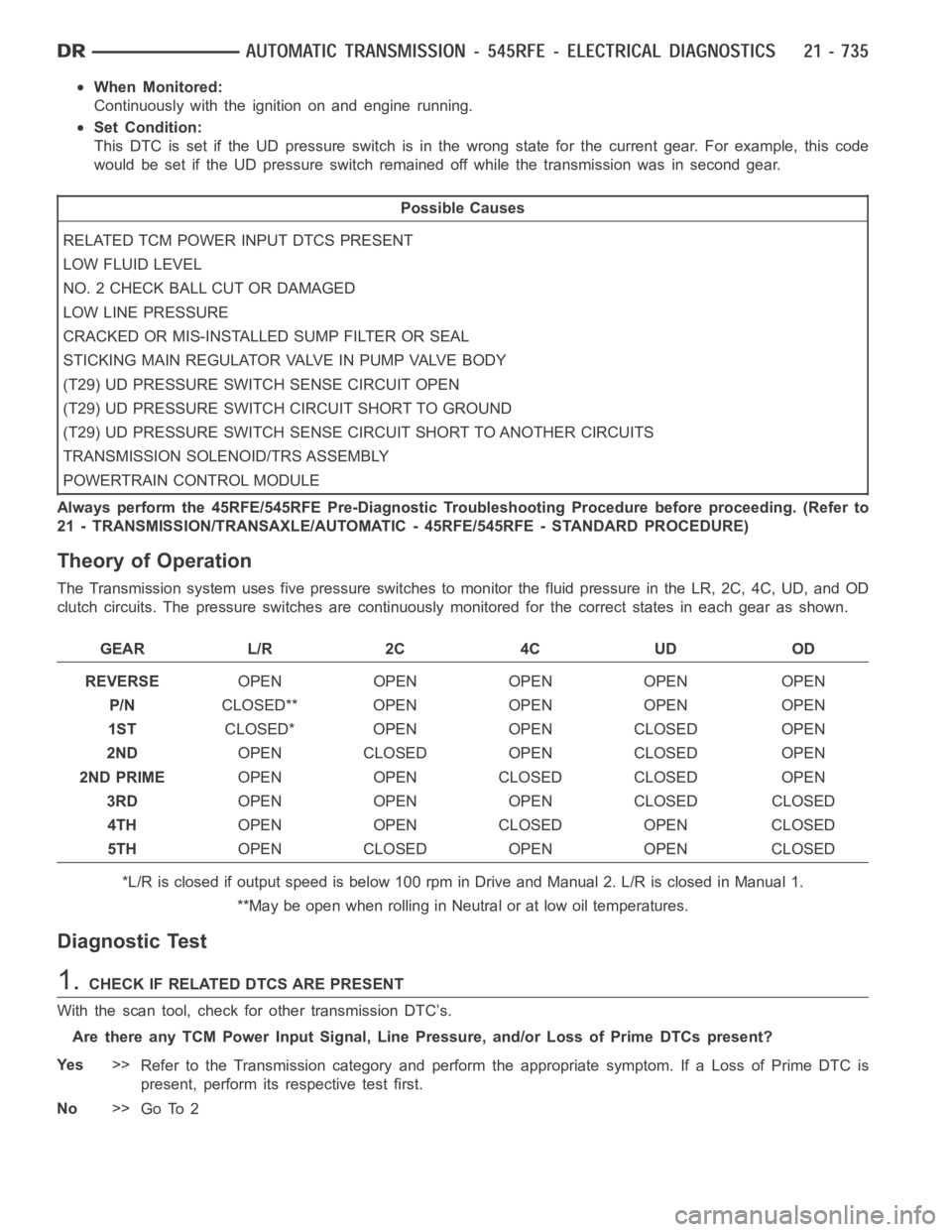
The Transmission system uses five pressure switches to monitor the fluid pressure in the LR, 2C, 4C, UD, and OD
clutch circuits. The pressure switches are continuously monitored for the correct states in each gear as shown.
GEAR L/R 2C 4C UD OD
REVERSEOPEN OPEN OPEN OPEN OPEN
P/NCLOSED** OPEN OPEN OPEN OPEN
1STCLOSED* OPEN OPEN CLOSED OPEN
2NDOPEN CLOSED OPEN CLOSED OPEN
2ND PRIMEOPEN OPEN CLOSED CLOSED OPEN
3RDOPEN OPEN OPEN CLOSED CLOSED
4THOPEN OPEN CLOSED OPEN CLOSED
5THOPEN CLOSED OPEN OPEN CLOSED
*L/R is closed if output speed is below 100 rpm in Drive and Manual 2. L/R is closed in Manual 1.
**May be open when rolling in Neutral or at low oil temperatures.
Diagnostic Test
1.CHECK IF RELATED DTCS ARE PRESENT
With the scan tool, check for other transmission DTC’s.
Are there any TCM Power Input Signal, Line Pressure, and/or Loss of Prime DTCs present?
Ye s>>
Refer to the Transmission category and perform the appropriate symptom. If a Loss of Prime DTC is
present, perform its respective test first.
No>>
Go To 2
Page 3258 of 5267
7.CHECK THE UD PRESSURE SWITCH STATUS
Refer to the DTC EVENT DATA recorded earlier.
Did the DTC P0876 set with the UD Pressure Switch closed?
Ye s>>
Go To 10
No>>
Go To 8
8.CHECK THE LINE PRESSURE
In the DTC EVENT DATA recorded earlier,compare the Line Pressure and the Desired Line Pressure.
Is the Line Pressure less than 40 psi, and significantly below the Desired Line Pressure?
Ye s>>
Repair as necessary to correct low line pressure. Check fluid level and adjustasnecessary.Iffluidlevel
is OK, check the Primary Oil Filter seal for a split, crack, or improperly installed. If the filter and seal are
OK, check the Main Regulator Valve in the Oil Pump. Refer to the Service Information for the above
procedures.
Perform 45RFE/545RFE TRANSMISSION VERIFICATION TEST - VER 1. (Refer to 21- TRANSMIS-
SION/TRANSAXLE/AUTOMATIC - 45RFE/545RFE - STANDARD PROCEDURE)
No>>
Go To 9
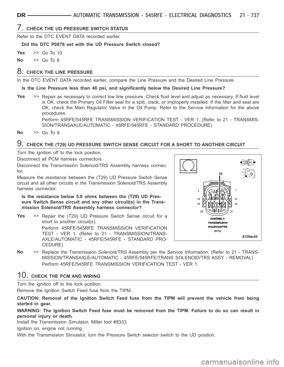
9.CHECK THE (T29) UD PRESSURE SWITCH SENSE CIRCUIT FOR A SHORT TO ANOTHER CIRCUIT
Turn the ignition off to the lock position.
Disconnect all PCM harness connectors.
Disconnect the Transmission Solenoid/TRS Assembly harness connec-
tor.
Measure the resistance between the (T29) UD Pressure Switch Sense
circuit and all other circuits in the Transmission Solenoid/TRS Assembly
harness connector.
Is the resistance below 5.0 ohms between the (T29) UD Pres-
sure Switch Sense circuit and any other circuit(s) in the Trans-
mission Solenoid/TRS Assembly harness connector?
Ye s>>
Repair the (T29) UD Pressure Switch Sense circuit for a
short to another circuit(s).
Perform 45RFE/545RFE TRANSMISSION VERIFICATION
TEST - VER 1. (Refer to 21 - TRANSMISSION/TRANS-
AXLE/AUTOMATIC - 45RFE/545RFE - STANDARD PRO-
CEDURE)
No>>
Replace the Transmission Solenoid/TRS Assembly per the Service Information. (Refer to 21 - TRANS-
MISSION/TRANSAXLE/AUTOMATIC - 45RFE/545RFE/TRANS SOLENOID/TRS ASSY -REMOVAL)
Perform 45RFE/545RFE TRANSMISSION VERIFICATION TEST - VER 1.
10.CHECK THE PCM AND WIRING
Turn the ignition off to the lock position.
Remove the Ignition Switch Feed fuse from the TIPM.
CAUTION: Removal of the Ignition Switch Feed fuse from the TIPM will prevent the vehicle from being
startedingear.
WARNING: The Ignition Switch Feed fuse must be removed from the TIPM. Failure to do so can result in
personal injury or death.
Install the Transmission Simulator, Miller tool #8333.
Ignition on, engine not running.
With the Transmission Simulator, turn the Pressure Switch selector switch to the UD position.
Page 3263 of 5267
When Monitored:
When the ignition is turned from
OFFposition toRUNposition and/or the ignition is turned fromSTART
position toRUNposition.
Set Condition:
This DTC is set when there is less than 3.0 volts present at the transmissioncontrol output circuits located in
the Powertrain Control Module (PCM) when the Transmission Control Systemrequest the power up of those
circuits.Note: Due to the integration of the Transmission Control Module and the Powertrain Control
Module, both systems have their own power and ground circuits..
Possible Causes
RELATED TIPM DTCS
(T515) TRANSMISSION CONTROL CIRCUIT SHORT TO GROUND
(T515) TRANSMISSION CONTROL CIRCUIT OPEN
POWERTRAIN CONTROL MODULE
Always perform the 45RFE/545RFE Pre-Diagnostic Troubleshooting Procedure before proceeding. (Refer to
21 - TRANSMISSION/TRANSAXLE/AUTOMATIC - 45RFE/545RFE - STANDARD PROCEDURE)
Theory of Operation
The Transmission Control Output circuit is used to supply power to the Transmission Solenoid/TRS Assembly and to
the PCM when in normal operating mode. The purpose of the Transmission Output circuit is to allow the Transmis-
sion Control System to turn off the power to the Transmission Solenoid/TRSAssembly in event that the transmission
should need to be placed into “limp-in” mode due to a DTC.
After a PCM reset, (ignition switch turned to the run position, or after cranking the engine) the Transmission Control
System verifies that the Transmission Output circuit is open by checking for voltage on the Transmission Output
circuits before the Transmission Control System request for the circuit to be powered up. The request is sent by a
direct circuit control from the PCM tothe TIPM. If the Transmission Control System detects less that 3.0 volts when
the output is commanded on, the DTC will set.Note: Inadequate Transmission Control Output voltage can also
cause DTCs P0846, P0869, P0871, P0876 or P0988 to set. Repairing the P0882 fault should also eliminate the
related DTCs.
Diagnostic Test
1.CHECK IF THE DTC P0882 IS CURRENT
With the scan tool, Check the STARTS SINCE SET counter for P0882.
NOTE: This counter only applies to the last DTC set.
Is the STARTS SINCE SET counter equal to 0?
Ye s>>
Go To 2
No>>
Go To 5
2.CHECK FOR TIPM RELATED DTCS
With the scan tool, check TIPM DTCs.
Are there any TCM TIPM DTCs present?
Ye s>>
Refer to the Transmission category and perform the appropriate symptom.
No>>
Go To 3
Page 3267 of 5267
When Monitored:
When the ignition is turned from
OFFposition toRUNposition and/or the ignition is turned fromSTART
position toRUNposition.
Set Condition:
This DTC is set if the Powertrain Control Module senses greater than 3.0 volts on the Transmission Control
Relay Output circuits prior to a request from the PCM to TIPM to energize theTransmission Output circuits.
Possible Causes
TIPM DTCS PRESENT
(T15) TRANSMISSION CONTROL CIRCUIT SHORT TO VOLTAGE
(T16) TRANSMISSION CONTROL OUTPUT CIRCUIT SHORT VOLTAGE
TRANSMISSION SOLENOID/TRS ASSEMBLY
POWERTRAIN CONTROL MODULE
Always perform the 45RFE/545RFE Pre-Diagnostic Troubleshooting Procedure before proceeding. (Refer to
21 - TRANSMISSION/TRANSAXLE/AUTOMATIC - 45RFE/545RFE - STANDARD PROCEDURE)
Theory of Operation
The Transmission Control Output circuit is used to supply power to the Transmission Solenoid/TRS Assembly and to
the PCM when in normal operating mode. The purpose of the Transmission Output circuit is to allow the Transmis-
sion Control System to turn off the power to the Transmission Solenoid/TRSAssembly in event that the transmission
should need to be placed into “limp-in” mode due to a DTC.
After a PCM reset, (ignition switch turned to the run position, or after cranking the engine) the Transmission Control
System verifies that the Transmission Output circuit is open by checking for voltage on the Transmission Output
circuits before the Transmission Control System request for the circuit to be powered up. The request is sent by a
direct circuit control from the PCM tothe TIPM. If voltage is detected on the Transmission Output circuits before the
request is sent, the DTC will set.
Diagnostic Test
1.CHECK FOR TCM TIPM DTCS
With the scan tool under TIPM, check for TCM Power Input DTCs.
Are there any TIPM TCM Power Input DTCS present?
Ye s>>
Refer to the Transmission category and perform the appropriate symptom.
No>>
Go To 2
2.CHECK TO SEE IF DTC P0883 IS CURRENT
With the scan tool, check the STARTS SINCE SET counter.
NOTE: This counter only applies to the last DTC set.
Is the STARTS SINCE SET counter set to 0?
Ye s>>
Go To 3
No>>
Go To 6
Page 3268 of 5267
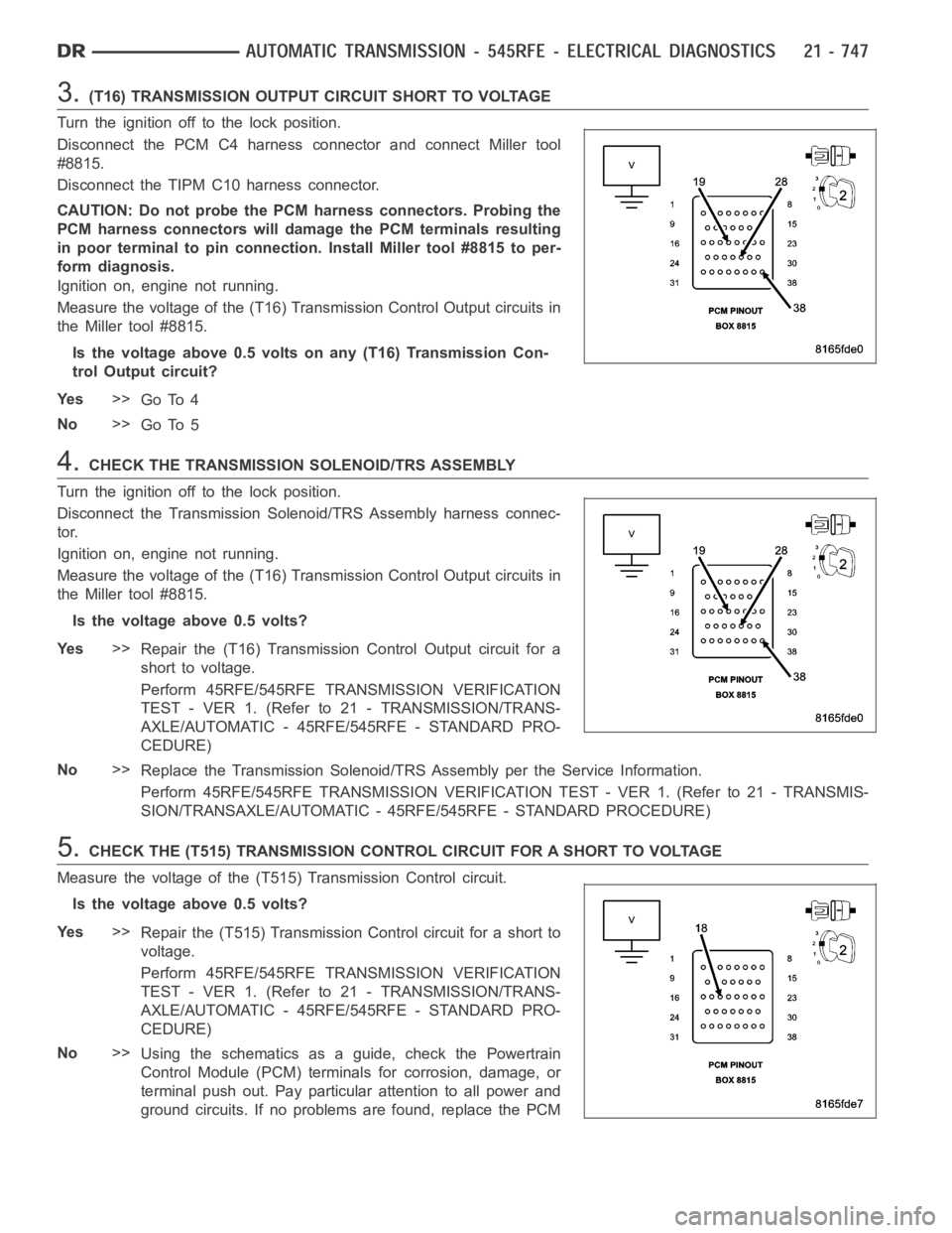
3.(T16) TRANSMISSION OUTPUT CIRCUIT SHORT TO VOLTAGE
Turn the ignition off to the lock position.
Disconnect the PCM C4 harness connector and connect Miller tool
#8815.
Disconnect the TIPM C10 harness connector.
CAUTION: Do not probe the PCM harness connectors. Probing the
PCM harness connectors will damage the PCM terminals resulting
in poor terminal to pin connection. Install Miller tool #8815 to per-
form diagnosis.
Ignition on, engine not running.
Measure the voltage of the (T16) Transmission Control Output circuits in
the Miller tool #8815.
Is the voltage above 0.5 volts on any (T16) Transmission Con-
trol Output circuit?
Ye s>>
Go To 4
No>>
Go To 5
4.CHECK THE TRANSMISSION SOLENOID/TRS ASSEMBLY
Turn the ignition off to the lock position.
Disconnect the Transmission Solenoid/TRS Assembly harness connec-
tor.
Ignition on, engine not running.
Measure the voltage of the (T16) Transmission Control Output circuits in
the Miller tool #8815.
Is the voltage above 0.5 volts?
Ye s>>
Repair the (T16) Transmission Control Output circuit for a
short to voltage.
Perform 45RFE/545RFE TRANSMISSION VERIFICATION
TEST - VER 1. (Refer to 21 - TRANSMISSION/TRANS-
AXLE/AUTOMATIC - 45RFE/545RFE - STANDARD PRO-
CEDURE)
No>>
Replace the Transmission Solenoid/TRS Assembly per the Service Information.
Perform 45RFE/545RFE TRANSMISSION VERIFICATION TEST - VER 1. (Refer to 21- TRANSMIS-
SION/TRANSAXLE/AUTOMATIC - 45RFE/545RFE - STANDARD PROCEDURE)
5.CHECK THE (T515) TRANSMISSION CONTROL CIRCUIT FOR A SHORT TO VOLTAGE
Measure the voltage of the (T515) Transmission Control circuit.
Is the voltage above 0.5 volts?
Ye s>>
Repair the (T515) Transmission Control circuit for a short to
voltage.
Perform 45RFE/545RFE TRANSMISSION VERIFICATION
TEST - VER 1. (Refer to 21 - TRANSMISSION/TRANS-
AXLE/AUTOMATIC - 45RFE/545RFE - STANDARD PRO-
CEDURE)
No>>
Using the schematics as a guide, check the Powertrain
Control Module (PCM) terminals for corrosion, damage, or
terminal push out. Pay particular attention to all power and
ground circuits. If no problems are found, replace the PCM
Page 3273 of 5267
When Monitored:
When the ignition is turned from
OFFposition toRUNposition and/or the ignition is turned fromSTART
position toRUNposition.
Set Condition:
This DTC is set if the Powertrain Control Module senses voltage on any of thepressure switch inputs prior to
the Transmission Control Output circuit being energized.
Possible Causes
PRESSURE SWITCH SENSE CIRCUITS SHORT TO VOLTAGE
TRANSMISSION SOLENOID/TRS ASSEMBLY
POWERTRAIN CONTROL MODULE
Always perform the 45RFE/545RFE Pre-Diagnostic Troubleshooting Procedure before proceeding. (Refer to
21 - TRANSMISSION/TRANSAXLE/AUTOMATIC - 45RFE/545RFE - STANDARD PROCEDURE)
Theory of Operation
The Totally Integrated Control Module (TIPM) replaces the Transmission control relay. The Transmission Control
Output circuit It is used to supply power to the solenoids and pressure switches (Transmission Solenoid/TRS
Assembly) when the transmission is in normal operating mode. When the Transmission Control Output circuit is off,
no power is supplied and the transmission.
Immediately after a controller reset (ignition key turned to the
runposition or after cranking engine), the TCM ver-
ifies that the Transmission Control Output circuits are open by checking for no voltage at the transmission control
output terminals at the PCM. After this is verified, the voltage at the pressure switches are checked. There should
be no voltage on the pressure switches at this time. The PCM will then activate the relay.
Diagnostic Test
1.CHECK FOR TIPM TCM DTCS
With the scan tool under TIPM, check for TCM Power Control DTCs.
Are there any TCM Power Control DTCs present?
Ye s>>
Refer to the Transmission category and perform the appropriate symptom.
No>>
Go To 2
2.CHECK TO SEE IF DTC P0890 IS PRESENT
With the scan tool, Check the STARTS SINCE SET counter for P0890.
NOTE: This counter only applies to the last DTC set.
Is the
Starts Since Setcounter set at 0?
Ye s>>
Go To 3
No>>
Go To 5
Page 3274 of 5267
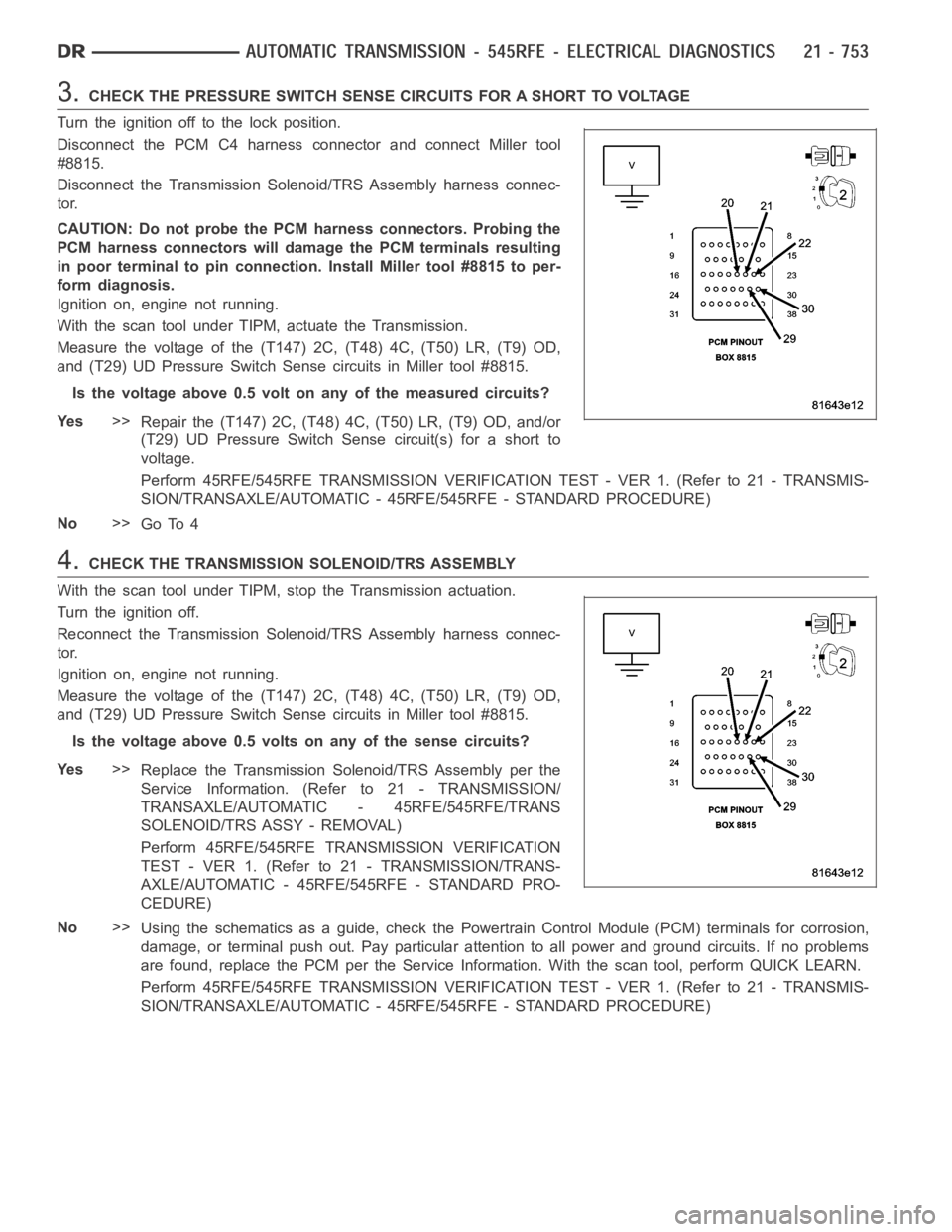
3.CHECK THE PRESSURE SWITCH SENSE CIRCUITS FOR A SHORT TO VOLTAGE
Turn the ignition off to the lock position.
Disconnect the PCM C4 harness connector and connect Miller tool
#8815.
Disconnect the Transmission Solenoid/TRS Assembly harness connec-
tor.
CAUTION: Do not probe the PCM harness connectors. Probing the
PCM harness connectors will damage the PCM terminals resulting
in poor terminal to pin connection. Install Miller tool #8815 to per-
form diagnosis.
Ignition on, engine not running.
With the scan tool under TIPM, actuate the Transmission.
Measure the voltage of the (T147) 2C, (T48) 4C, (T50) LR, (T9) OD,
and (T29) UD Pressure Switch Sense circuits in Miller tool #8815.
Is the voltage above 0.5 volt on any of the measured circuits?
Ye s>>
Repair the (T147) 2C, (T48) 4C, (T50) LR, (T9) OD, and/or
(T29) UD Pressure Switch Sense circuit(s) for a short to
voltage.
Perform 45RFE/545RFE TRANSMISSION VERIFICATION TEST - VER 1. (Refer to 21- TRANSMIS-
SION/TRANSAXLE/AUTOMATIC - 45RFE/545RFE - STANDARD PROCEDURE)
No>>
Go To 4
4.CHECK THE TRANSMISSION SOLENOID/TRS ASSEMBLY
With the scan tool under TIPM, stop the Transmission actuation.
Turn the ignition off.
Reconnect the Transmission Solenoid/TRS Assembly harness connec-
tor.
Ignition on, engine not running.
Measure the voltage of the (T147) 2C, (T48) 4C, (T50) LR, (T9) OD,
and (T29) UD Pressure Switch Sense circuits in Miller tool #8815.
Is the voltage above 0.5 volts on any of the sense circuits?
Ye s>>
Replace the Transmission Solenoid/TRS Assembly per the
Service Information. (Refer to 21 - TRANSMISSION/
TRANSAXLE/AUTOMATIC - 45RFE/545RFE/TRANS
SOLENOID/TRS ASSY - REMOVAL)
Perform 45RFE/545RFE TRANSMISSION VERIFICATION
TEST - VER 1. (Refer to 21 - TRANSMISSION/TRANS-
AXLE/AUTOMATIC - 45RFE/545RFE - STANDARD PRO-
CEDURE)
No>>
Using the schematics as a guide, check the Powertrain Control Module (PCM)terminals for corrosion,
damage, or terminal push out. Pay particular attention to all power and ground circuits. If no problems
are found, replace the PCM per the Service Information. With the scan tool,perform QUICK LEARN.
Perform 45RFE/545RFE TRANSMISSION VERIFICATION TEST - VER 1. (Refer to 21- TRANSMIS-
SION/TRANSAXLE/AUTOMATIC - 45RFE/545RFE - STANDARD PROCEDURE)
Page 3277 of 5267
When Monitored:
Continuously with the ignition on, engine running, with the transmissionin gear.
Set Condition:
The PCM continuously monitors Actual Line Pressure and compares it to DesiredLinePressure.IftheActual
Line Pressure reading is more than 172.4 kPa (25 psi) higher than the Desired Line Pressure, but is less than
the highest Line Pressure ever used in the current gear, the DTC sets.
Possible Causes
RELATED DTC’S PRESENT
LINE PRESSURE CONNECTOR AND WIRING
INTERNAL TRANSMISSION
POWERTRAIN CONTROL MODULE
Always perform the 45RFE/545RFE Pre-Diagnostic Troubleshooting Procedure before proceeding. (Refer to
21 - TRANSMISSION/TRANSAXLE/AUTOMATIC - 45RFE/545RFE - STANDARD PROCEDURE)
Theory of Operation
Line pressure is electronically controlled by the Transmission Control System and is measured by the Line Pressure
Sensor (LPS). The desired line pressure is continuously being compared tothe actual line pressure and is regulated
by electronically changing the dutycycle of the Pressure Control Solenoid (PCS). (5% duty cycle = solenoid off =
max line pressure, 62% duty cycle =solenoid on = min line pressure).
The Transmission Control System calculates the desired line pressure based on inputs from the transmission and
engine. A calculated torque input to the transmission is used as the primary input of the desired line pressure cal-
culation and is called Torque Based Line Pressure. In addition, the line pressure is set to a preset level 827 to 931
kPa (120 to 135 psi) during shifts and in Park and Neutral to ensure consistent shift quality.
Diagnostic Test
1.DETERMINING IF RELATED DTCS ARE PRESENT
With the scan tool, check for other transmission DTCs.
Are there any other line pressure related DTCs present?
Ye s>>
Refer to the Transmission category and perform the appropriate symptom. Perform the test for P0934
and/or P0935 first if present.
No>>
Go To 2
2.COMPARE ACTUAL LINE PRESSURE TO DESIRED LINE PRESSURE
CAUTION: Apply Parking Brake
Start the engine.
CAUTION: Firmly apply the brakes.
With the scan tool, monitor the Line Pressure, Desired Line Pressure and the TPS degrees.
While firmly applying the brakes, place the shifter in reverse, then slowly press the accelerator pedal to a TPS
degree of 15°.
Compare the Line Pressure reading to the Desired Line Pressure reading on the scan tool.
Does the Line Pressure stay within ± 34 kPa or 5 psi of the Desired Line Pressure?
No>>
Go To 3
Ye s>>
Go To 5