Page 3052 of 5267
INSTALLATION
1. Install the output speed sensor (2) into the trans-
mission case.
NOTE: Before installing the speed sensor bolt, it
will be necessary to replenish the sealing patch on
the bolt using MOPAR
Lock & Seal Adhesive.
2. Install the bolt to hold the output speed sensor into
the transmission case. Tighten the bolt to 9 Nꞏm
(80 in.lbs.).
3. Install the wiring connector onto the output speed
sensor
4. Verify the transmission fluid level. Add fluid as nec-
essary.
5. Lower vehicle.
Page 3055 of 5267

SOLENOID-PRESSURE CONTROL
DESCRIPTION
Thepressurecontrolsolenoid(1)ismountedonthe
top of the valve body, next to the line pressure sensor
(2).
The TCM utilizes a closed-loop system to control
transmission line pressure. The system contains a
variable force style solenoid, the Pressure Control
Solenoid. The solenoid is duty cycle controlled by the
TCM to vent the unnecessary line pressure supplied
by the oil pump back to the sump. The system also
contains a variable pressure style sensor, the Line
Pressure Sensor, which is a direct input to the TCM.
The line pressure solenoid monitors the transmission
line pressure and completes the feedback loop to the
TCM. The TCM uses this information to adjust its con-
trol of the pressure control solenoid to achieve the
desired line pressure.
OPERATION
The pressure control solenoid (PCS) is a variable force (VFS) style solenoid. A VFS solenoid is an electro-hydraulic
actuator, combining a solenoid and a regulating valve.
The transmission control module varies the current for the PCS, which variesthepressureinthelinepressure
hydraulic circuit. When the current (duty cycle) of the PCS is low, the pressure in the circuit is higher. At 0 current
(0% duty cycle), the pressure is at the maximum value. Conversely, when thecurrent is maximized (100% duty
cycle), the pressure in the circuit is at the lowest possible value.
REMOVAL
1. Remove the valve body from the transmission.
(Refer to 21 - TRANSMISSION/TRANSAXLE/AU-
TOMATIC - 42RLE/VALVE BODY - REMOVAL)
2. Remove the electrical connectors from the pres-
sure control solenoid (1) and the line pressure sen-
sor (2).
3. Remove the screws (6) holding the pressure con-
trol solenoid (1) and line pressure sensor (2) to the
valve body.
4. Remove the pressure control solenoid and line
pressure sensor from the valve body.
Page 3056 of 5267
INSTALLATION
1. Install the pressure control solenoid (1) and line
pressure sensor (2) into the valve body.
2. Install the screws (6) to hold the pressure control
solenoid (1) and line pressure sensor (2) to the
valve body.
3. Install the electrical connectors to the pressure
control solenoid (1) and the line pressure sensor
(2).
4. Install the valve body into the transmission. (Refer
to 21 - TRANSMISSION/TRANSAXLE/AUTOMATIC
- 42RLE/VALVE BODY - INSTALLATION)
Page 3074 of 5267

SENSOR-TRANSMISSION RANGE
DESCRIPTION
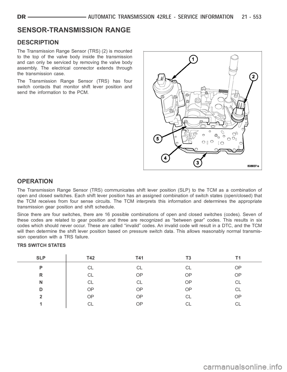
The Transmission Range Sensor (TRS) (2) is mounted
to the top of the valve body inside the transmission
and can only be serviced by removing the valve body
assembly. The electrical connector extends through
the transmission case.
The Transmission Range Sensor (TRS) has four
switch contacts that monitor shift lever position and
send the information to the PCM.
OPERATION
The Transmission Range Sensor (TRS) communicates shift lever position (SLP) to the TCM as a combination of
open and closed switches. Each shift lever position has an assigned combination of switch states (open/closed) that
the TCM receives from four sense circuits. The TCM interprets this information and determines the appropriate
transmission gear position and shift schedule.
Since there are four switches, there are 16 possible combinations of open and closed switches (codes). Seven of
these codes are related to gear position and three are recognized as “between gear” codes. This results in six
codes which should never occur. These are called “invalid” codes. An invalid code will result in a DTC, and the TCM
will then determine the shift lever position based on pressure switch data. This allows reasonably normal transmis-
sion operation with a TRS failure.
TRS SWITCH STATES
SLP T42 T41 T3 T1
PCL CL CL OP
RCL OP OP OP
NCL CL OP CL
DOP OP OP CL
2OP OP CL OP
1CL OP CL CL
Page 3077 of 5267

SENSOR-TRANSMISSION TEMPERATURE
DESCRIPTION
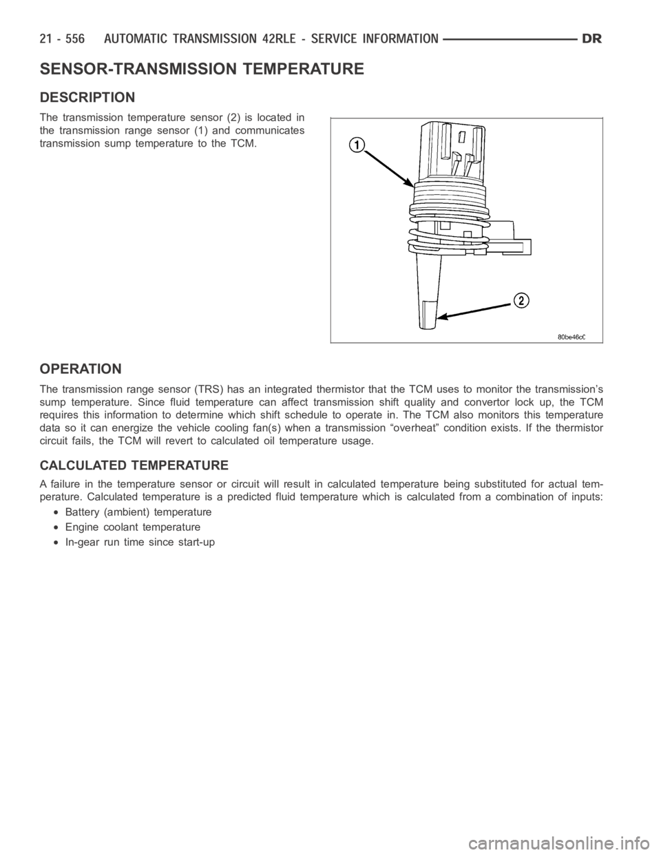
The transmission temperature sensor (2) is located in
the transmission range sensor (1) and communicates
transmission sump temperature to the TCM.
OPERATION
The transmission range sensor (TRS) has an integrated thermistor that theTCM uses to monitor the transmission’s
sump temperature. Since fluid temperature can affect transmission shiftquality and convertor lock up, the TCM
requires this information to determine which shift schedule to operate in. The TCM also monitors this temperature
data so it can energize the vehicle cooling fan(s) when a transmission “overheat” condition exists. If the thermistor
circuit fails, the TCM will revert to calculated oil temperature usage.
CALCULATED TEMPERATURE
A failure in the temperature sensor or circuit will result in calculated temperature being substituted for actual tem-
perature. Calculated temperature is a predicted fluid temperature whichis calculated from a combination of inputs:
Battery (ambient) temperature
Engine coolant temperature
In-gear run time since start-up
Page 3078 of 5267
BODY-VALVE
DESCRIPTION
The valve body assembly consists of a cast aluminum
valve body (5), separator plate (4), and transfer plate
(3). The valve body contains valves and check balls
that control fluid delivery to the torque converter
clutch, solenoid/pressure switch assembly, and fric-
tional clutches.
Also mounted to the valve body assembly are the
solenoid/pressure switch assembly and the transmis-
sion range sensor (2).
Page 3084 of 5267
1. Disconnect the transmission range sensor (5) and
solenoid/pressure switchassembly wiring connec-
tors.
2. Disconnect the variable line pressure connector (4),
if equipped.
3. Disconnect the shift cable from the shift lever (at
the transmission).
4. Move the manual shift lever clockwise as far as it
will go. This should be one position past the L posi-
tion. Then remove the manual shift lever.
NOTE: One of the oil pan bolts has a sealing patch
applied from the factory. Separate this bolts for
reuse.
5. Remove transmission pan bolts (2).
6. Remove transmission oil pan (1).
Page 3086 of 5267
1. Remove the electrical connectors from the pres-
sure control solenoid (1) and the line pressure sen-
sor (2).
2. Remove the screws (6) holding the pressure con-
trol solenoid (1) and line pressure sensor (2) to the
valve body.
3. Remove the pressure control solenoid and line
pressure sensor from the valve body.
4. Remove the shoulder screw (3) holding the vari-
able line pressure header (4) to the valve body.
5. Remove the variable line pressure header from the
manual shaft (5).
6. Remove manual shaft seal.
7. Remove manual shaft screw (1).