Page 2911 of 5267
MECHANISM-SHIFT
DESCRIPTION ............................... 536
OPERATION ................................. 536
SOLENOID
DESCRIPTION ............................... 537
OPERATION ................................. 538
ASSEMBLY-TRANSMISSION SOLENOID/
PRESSURE SWITCH
DESCRIPTION ............................... 539
OPERATION ................................. 539
REMOVAL ................................... 540
INSTALLATION .............................. 541
CONVERTER-TORQUE
DESCRIPTION ............................... 542
OPERATION ................................. 546
REMOVAL ................................... 548
INSTALLATION .............................. 549
SWITCH-TOW/HAUL OVERDRIVE
DESCRIPTION ............................... 550
OPERATION ................................. 550REMOVAL ................................... 550
INSTALLATION .............................. 551
RELAY-TRANSMISSION CONTROL
DESCRIPTION ............................... 552
OPERATION ................................. 552
SENSOR-TRANSMISSION RANGE
DESCRIPTION ............................... 553
OPERATION ................................. 553
REMOVAL ................................... 554
INSTALLATION .............................. 555
SENSOR-TRANSMISSION TEMPERATURE
DESCRIPTION ............................... 556
OPERATION ................................. 556
BODY-VALVE
DESCRIPTION ............................... 557
OPERATION ................................. 558
REMOVAL ................................... 562
DISASSEMBLY .............................. 564
ASSEMBLY .................................. 571
INSTALLATION .............................. 578
Page 2914 of 5267
The 42RLE is a four-speed transmission that is a conventional hydraulic/mechanical assembly controlled with adap-
tive electronic controls and monitors. The hydraulic system of the transmission consists of the transmission fluid,
fluid passages, hydraulic valves, and various line pressure control components. An input clutch assembly which
houses the underdrive, overdrive, and reverse clutches is used. It also utilizes separate holding clutches: 2nd/4th
gear and Low/Reverse. The primary mechanical components of the transmission consist of the following:
Three multiple disc input clutches
Two multiple disc holding clutches
Four hydraulic accumulators
Two planetary gear sets
Hydraulic oil pump
Valve body
Solenoid/Pressure switch assembly
Control of the transmission is accomplished by fully adaptive electronics. Optimum shift scheduling is accomplished
through continuous real-time sensor feedback information provided to the Transmission Control Module (TCM) por-
tion of the Powertrain Control Module (PCM).
The TCM is the heart of the electronic control system and relies on information from various direct and indirect
inputs (sensors, switches, etc.) to determine driver demand and vehicle operating conditions. With this information,
the TCM can calculate and perform timely and quality shifts through various output or control devices (solenoid
pack, transmission control relay, etc.).
The TCM also performs certain self-diagnostic functions and provides comprehensive information (sensor data,
DTC’s, etc.) which is helpful in proper diagnosis and repair. This informationcanbeviewedwiththescantool.
TRANSMISSION IDENTIFICATION
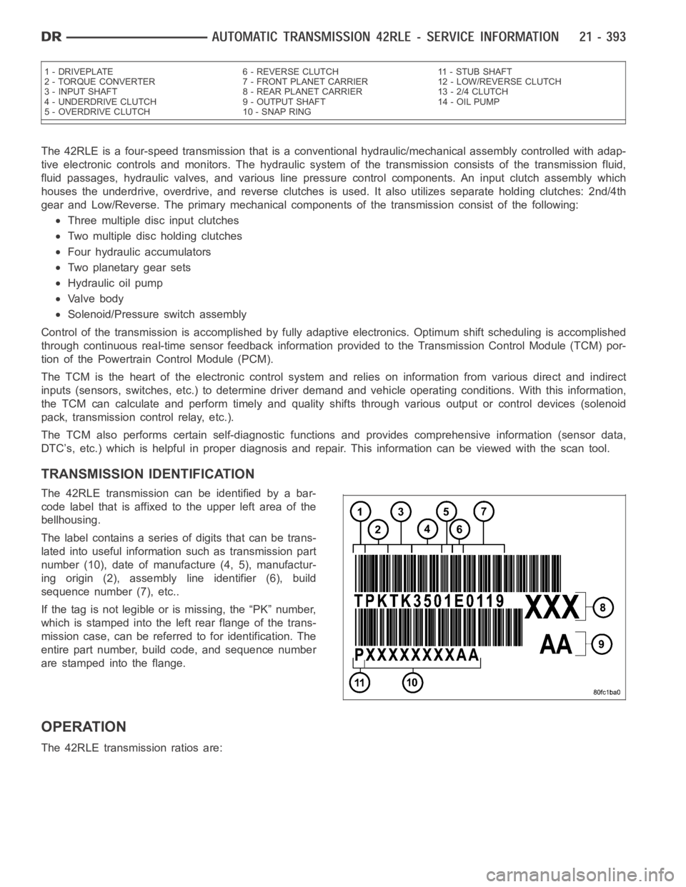
The 42RLE transmission can be identified by a bar-
code label that is affixed to the upper left area of the
bellhousing.
The label contains a series of digits that can be trans-
lated into useful information such as transmission part
number (10), date of manufacture (4, 5), manufactur-
ing origin (2), assembly line identifier (6), build
sequence number (7), etc..
If the tag is not legible or is missing, the “PK” number,
which is stamped into the left rear flange of the trans-
mission case, can be referred to for identification. The
entire part number, build code, and sequence number
are stamped into the flange.
OPERATION
The 42RLE transmission ratios are:
1 - DRIVEPLATE 6 - REVERSE CLUTCH 11 - STUB SHAFT
2 - TORQUE CONVERTER 7 - FRONT PLANET CARRIER 12 - LOW/REVERSE CLUTCH
3 - INPUT SHAFT 8 - REAR PLANET CARRIER 13 - 2/4 CLUTCH
4 - UNDERDRIVE CLUTCH 9 - OUTPUT SHAFT 14 - OIL PUMP
5 - OVERDRIVE CLUTCH 10 - SNAP RING
Page 2925 of 5267
TORQUE CONVERTER LEAKAGE
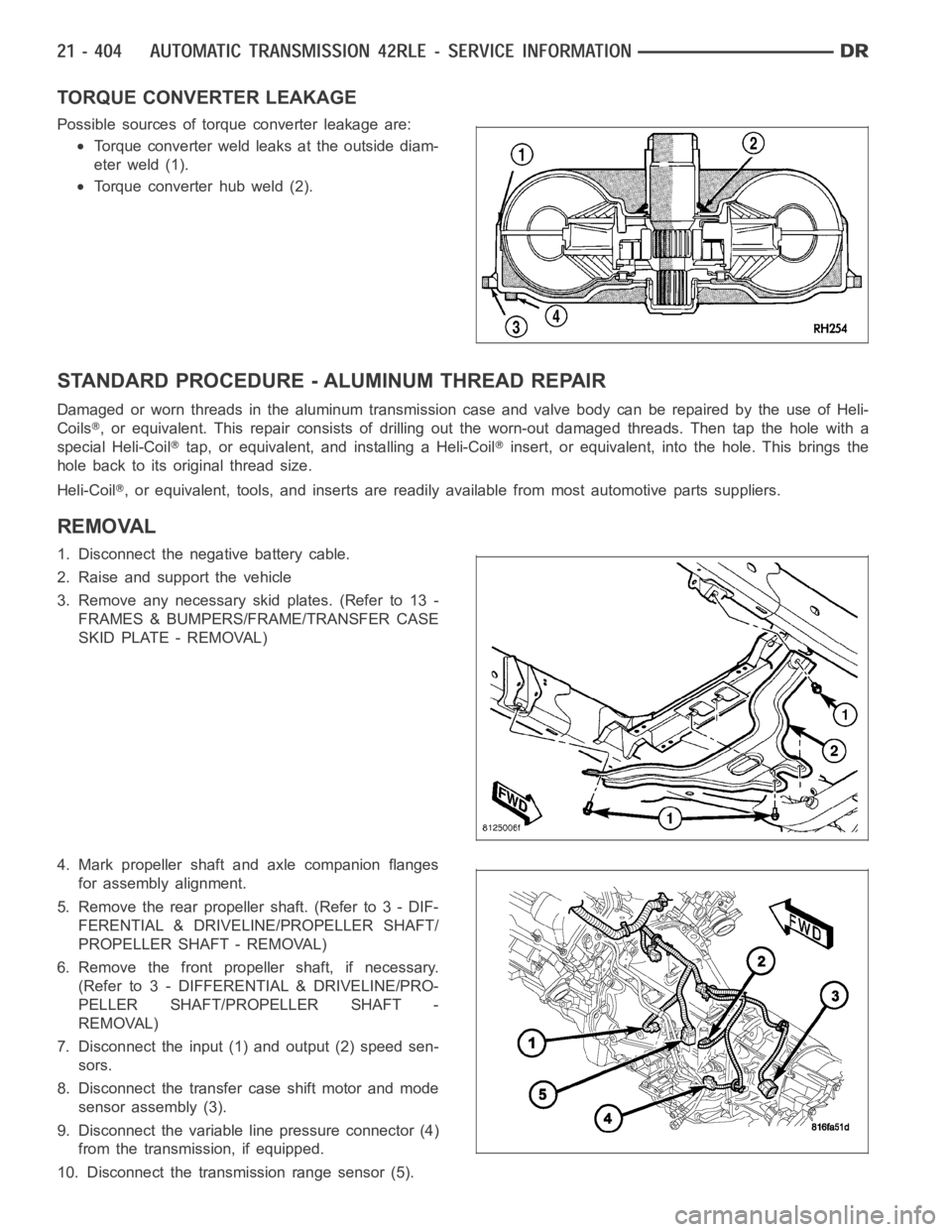
Possible sources of torque converter leakage are:
Torque converter weld leaks at the outside diam-
eter weld (1).
Torque converter hub weld (2).
STANDARD PROCEDURE - ALUMINUM THREAD REPAIR
DamagedorwornthreadsinthealuminumtransmissioncaseandvalvebodycanberepairedbytheuseofHeli-
Coils
, or equivalent. This repair consists of drilling out the worn-out damagedthreads. Then tap the hole with a
special Heli-Coil
tap, or equivalent, and installing a Heli-Coilinsert, or equivalent, into the hole. This brings the
hole back to its original thread size.
Heli-Coil
, or equivalent, tools, and inserts are readily available from most automotive parts suppliers.
REMOVAL
1. Disconnect the negative battery cable.
2. Raise and support the vehicle
3. Remove any necessary skid plates. (Refer to 13 -
FRAMES & BUMPERS/FRAME/TRANSFER CASE
SKID PLATE - REMOVAL)
4. Mark propeller shaft and axle companion flanges
for assembly alignment.
5. Remove the rear propeller shaft. (Refer to 3 - DIF-
FERENTIAL & DRIVELINE/PROPELLER SHAFT/
PROPELLER SHAFT - REMOVAL)
6. Remove the front propeller shaft, if necessary.
(Refer to 3 - DIFFERENTIAL & DRIVELINE/PRO-
PELLER SHAFT/PROPELLER SHAFT -
REMOVAL)
7. Disconnect the input (1) and output (2) speed sen-
sors.
8. Disconnect the transfer case shift motor and mode
sensor assembly (3).
9. Disconnect the variable line pressure connector (4)
from the transmission, if equipped.
10. Disconnect the transmission range sensor (5).
Page 2932 of 5267
NOTE: The speed sensor bolts have a sealing
patch applied from the factory. Separate these
bolts for reuse.
11. Remove the input speed sensor bolt.
NOTE: The speed sensor bolts have a sealing
patch applied from the factory. Separate these
bolts for reuse.
12. Remove the output speed sensor bolt.
13. Remove the input and output (2) speed sensors.
Identify the speed sensors for re-installation since
they are not interchangeable.
Page 2962 of 5267
37. Install front carrier/rear annulus assembly (2) and
#6 needle bearing (1).
38. Install front sun gear assembly (1) and #4 thrust
washer (2).
39. Determine proper #4 thrust plate thickness. Select
the thinnest available #4 thrust plate.
40. Install #4 thrust plate (2) using petrolatum to hold
into position.
41. Install input clutch assembly. Ensure the input
clutch assembly is completely seated by viewing
position through input speed sensor hole.If the
speed sensor tone wheel is not centered in
the opening, the input clutches assembly is
not seated properly.
Page 2968 of 5267
NOTE: Before installing the oil pan bolt in the bolt
hole located between the torque converter clutch
on and U/D clutch pressure tap circuits , it will be
necessary to replenish the sealing patch on the
bolt using MOPAR
Lock & Seal Adhesive.
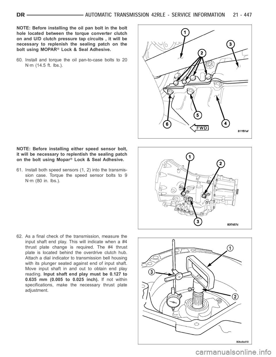
60. Install and torque the oil pan-to-case bolts to 20
Nꞏm (14.5 ft. lbs.).
NOTE: Before installing either speed sensor bolt,
it will be necessary to replentish the sealing patch
on the bolt using Mopar
Lock & Seal Adhesive.
61. Install both speed sensors (1, 2) into the transmis-
sion case. Torque the speed sensor bolts to 9
Nꞏm (80 in. lbs.).
62. As a final check of the transmission, measure the
input shaft end play. This will indicate when a #4
thrust plate change is required. The #4 thrust
plate is located behind the overdrive clutch hub.
Attach a dial indicator to transmission bell housing
with its plunger seated against end of input shaft.
Move input shaft in and out to obtain end play
reading.Input shaft end play must be 0.127 to
0.635 mm (0.005 to 0.025 inch).If not within
specifications, make the necessary thrust plate
adjustment.
Page 2973 of 5267
12. Carefully work transmission forward and over engine block dowels until converter hub is seated in crankshaft.
Verify that no wires, or the transmission vent hose, have become trapped between the engine block and the
transmission.
13. Install two bolts to attach the transmission to the engine.
14. Install remaining torque converter housing to engine bolts. Tighten to 68 Nꞏm (50 ft.lbs.).
15. Install transfer case, if equipped. Tighten transfer case nuts to 35 Nꞏm (26 ft.lbs.).
16. Install rear transmission crossmember. Tighten crossmember to framebolts to 68 Nꞏm (50 ft.lbs.).
17. Install rear support to transmission. Tighten bolts to 47 Nꞏm (35 ft.lbs.).
18. Lower transmission onto crossmember and install bolts attaching transmission mount to crossmember. Tighten
clevis bracket to crossmember bolts to 47 Nꞏm (35 ft.lbs.). Tighten the clevis bracket to rear support bolt to 68
Nꞏm (50 ft.lbs.).
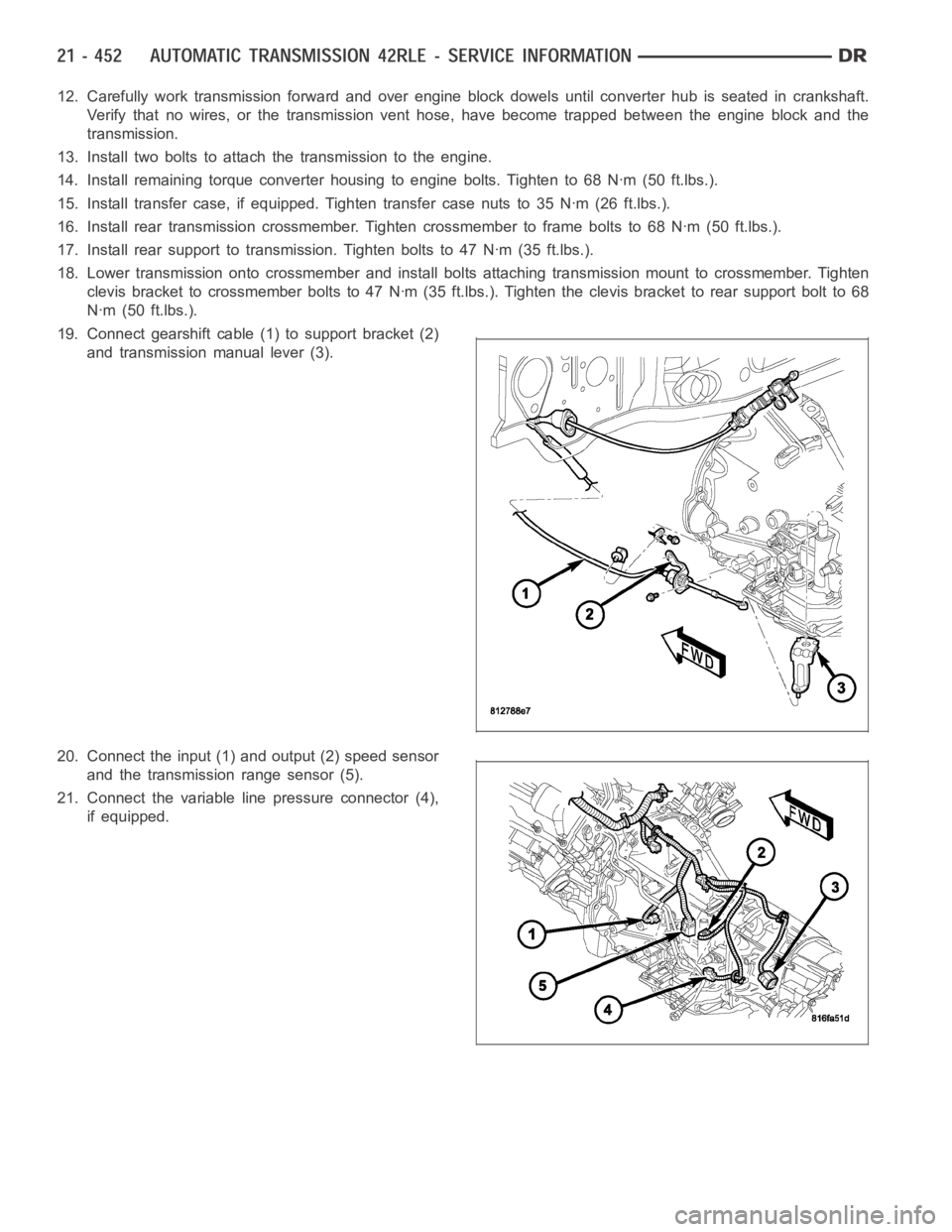
19. Connect gearshift cable (1) to support bracket (2)
and transmission manual lever (3).
20. Connect the input (1) and output (2) speed sensor
and the transmission range sensor (5).
21. Connect the variable line pressure connector (4),
if equipped.
Page 3001 of 5267
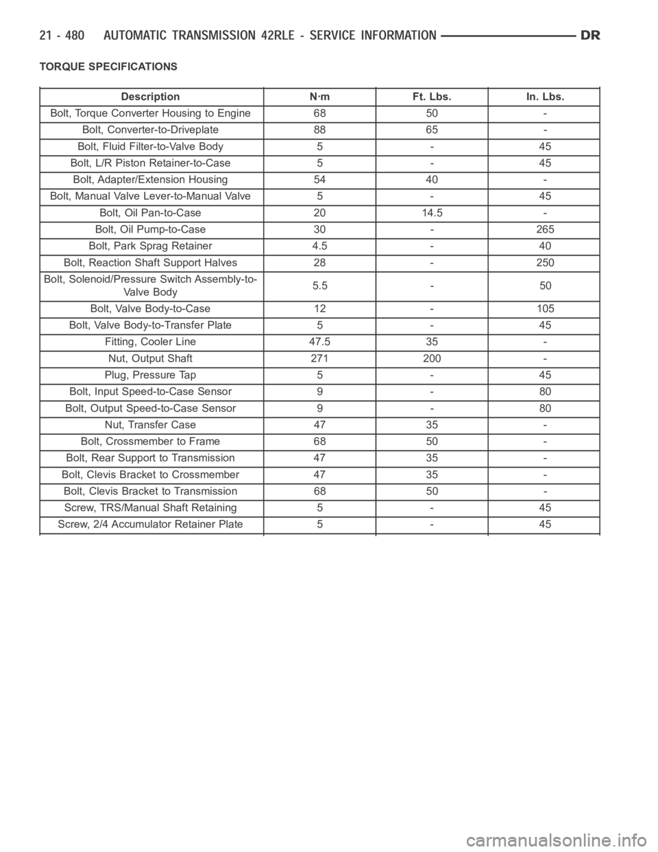
TORQUE SPECIFICATIONS
Description Nꞏm Ft. Lbs. In. Lbs.
Bolt, Torque Converter Housing to Engine 68 50 -
Bolt, Converter-to-Driveplate 88 65 -
Bolt, Fluid Filter-to-Valve Body 5 - 45
Bolt, L/R Piston Retainer-to-Case 5 - 45
Bolt, Adapter/Extension Housing 54 40 -
Bolt, Manual Valve Lever-to-Manual Valve 5 - 45
Bolt, Oil Pan-to-Case 20 14.5 -
Bolt, Oil Pump-to-Case 30 - 265
Bolt, Park Sprag Retainer 4.5 - 40
Bolt, Reaction Shaft Support Halves 28 - 250
Bolt, Solenoid/Pressure Switch Assembly-to-
Valve Body5.5 - 50
Bolt, Valve Body-to-Case 12 - 105
Bolt, Valve Body-to-Transfer Plate 5 - 45
Fitting, Cooler Line 47.5 35 -
Nut, Output Shaft 271 200 -
Plug, Pressure Tap 5 - 45
Bolt, Input Speed-to-Case Sensor 9 - 80
Bolt, Output Speed-to-Case Sensor 9 - 80
Nut, Transfer Case 47 35 -
Bolt, Crossmember to Frame 68 50 -
Bolt, Rear Support to Transmission 47 35 -
Bolt, Clevis Bracket to Crossmember 47 35 -
Bolt, Clevis Bracket to Transmission 68 50 -
Screw, TRS/Manual Shaft Retaining 5 - 45
Screw, 2/4 Accumulator Retainer Plate 5 - 45