Page 2165 of 2893

Cavity Wire Test conditionTest: Desired result Possible cause if desired result
is not obtained
22-215
4. With the power window master switch still disconnected, do these input tests at the following connector.
If any test indicates a problem, find and correct the cause, then recheck the system.
If all the input tests prove OK, go to step 5.
9 GRN Connect terminals No. 4
and No. 9, and terminals
No. 10 and No. 11
momentarily with jumper
wires Check driver’s power window
motor operation:
The window should go down.
Faulty driver’s power window
motor
An open in the wire
10 YEL Connect terminals No. 4 and No. 10, and terminals
No. 9 and No. 11
momentarily with jumper
wires Check driver’s power window
motor operation:
The window should go up.
1 ORN Connect terminals No. 3 and No. 2, and terminals
No. 1 and No. 12
momentarily with jumper
wires Check front passenger’s
power window motor
operation:
The window should go down.
Faulty front passenger’s
power window motor
Faulty front passenger’s
power window switch
An open in the wire
2 BRN Connect terminals No. 3 and No. 1, and terminals
No. 2 and No. 12
momentarily with jumper
wires Check front passenger’s
power window motor
operation:
The window should go up.
13 LT BLUConnect terminals No. 15
and No. 14, and terminals
No. 13 and No. 12
momentarily with jumper
wires Check right rear power
window motor operation:
The window should go down.
Faulty right rear power
window motor
Faulty right rear power
window switch
An open in the wire
14 RED Connect terminals No. 15 and No. 13, and terminals
No. 14 and No. 12
momentarily with jumper
wires Check right rear power
window motor operation:
The window should go up.
21 PUR Connect terminals No. 20 and No. 21, and terminals
No. 22 and No. 12
momentarily with jumper
wires Check left rear power window
motor operation:
The window should go down.
Faulty left rear power window
motor
Faulty left rear power window
switch
An open in the wire
22 GRN Connect terminals No. 20 and No. 22, and terminals
No. 21 and No. 12
momentarily with jumper
wires Check left rear power window
motor operation:
The window should go up.
(cont’d)
08/08/21 14:28:40 61SNR030_220_0217
ProCarManuals.com
DYNOMITE -2009-
Page 2166 of 2893

5. Reconnect")
�µ
�µ�µ
�µ
�µ�µ
Cavity Wire Test condition Test: Desired result Possible cause if desired result is not
obtained
22-216Power Windows
Power Window Master Switch Input Test (cont’d)
5. Reconnect the 22P connector to the power window master switch. Turn the ignition switch to ON (II), and do these input tests at the
following connector.
If any test indicates a problem, find and correct the cause, then recheck the system.
If all the input tests prove OK, the control unit must be faulty; replace the power window master switch.
3 GRN Ignition switch ON (II) Measure the voltage to ground:
There should be battery voltage.Blown No. 30 (20 A) fuse in the under-
dash fuse/relay box
Faulty power window relay
Faulty MICU
An open in the wire
4 WHT Under all conditions Measure the voltage to ground: There should be battery voltage.Blown No. 26 (20 A) fuse in the under-
dash fuse/relay box
An open in the wire
15 RED Ignition switch ON (II) Measure the voltage to ground: There should be battery voltage.Blown No. 32 (20 A) fuse in the under-
dash fuse/relay box
Faulty power window relay
Faulty MICU
An open in the wire
20 PUR Ignition switch ON (II) Measure the voltage to ground: There should be battery voltage.Blown No. 33 (20 A) fuse in the under-
dash fuse/relay box
Faulty power window relay
Faulty MICU
An open in the wire
7 BRN Under all conditions Measure the voltage to ground: There should be less than 0.5 V.Poor ground (G503)
An open in the wire
11 BLK Under all conditions Measure the voltage to ground: There should be less than 0.5 V.Poor ground (G503)
An open in the wire
12 BLK Under all conditions Measure the voltage to ground: There should be less than 0.5 V.Poor ground (G503)
An open in the wire
16 PUR Ignition switch ON (II) Measure the voltage to ground: There should be battery voltage.Faulty power window master switch
A short to ground in the wire
5 PNK Ignition switch ON (II), and driver’s power window switch
moving up or down Measure the voltage between
terminals No. 5 and No. 7:
There should be 0 V about
5 V 0 V about 5 V repeatedly
(a digital voltmeter should read
about 2.5 V while the window
moves). Faulty power window master switch
Faulty driver’s power window motor
An open in the wire
A short to ground in the wire
6 ORN Ignition switch ON (II), and driver’s power window switch
moving up or down Measure the voltage between
terminals No. 6 and No. 7:
There should be 0 V about
5 V 0 V about 5 V repeatedly
(a digital voltmeter should read
about 2.5 V while the window
moves).
6. Reset the power window control unit (see page 22-210).
08/08/21 14:28:40 61SNR030_220_0218
ProCarManuals.com
DYNOMITE -2009-
Page 2167 of 2893
����
Motor Test
Pulser Test
22-217
Driver’s Power Window Motor Test
Terminal
Direction 14
UP
DOWN
1. Remove the door pane")
�´�µ
�´�µ
�´�µ
���
����
�(�#�'���������������������������
���
�������)����
Motor Test
Pulser Test
22-217
Driver’s Power Window Motor Test
Terminal
Direction 14
UP
DOWN
1. Remove the door panel (see page 20-7).
2. Disconnect the 6P connector from the driver’s power window motor.
3. Test the motor in each direction by connecting battery power and ground according to the table.
When the motor stops running, disconnect one
lead immediately.
4. If the motor does not run or fails to run smoothly, replace it. 5. Reconnect the 6P connector to the driver’s power
window motor.
6. Turn the ignition switch to ON (II).
7. Measure the voltage between the terminals. There should be battery voltage betweenterminals No. 6 ( ) and No. 5 ( ).
Connect an analog voltmeter between terminals No. 3 ( ) and No. 5 ( ), and run the power
window motor down or up. The voltmeter needle
should move back and forth alternately between
0 V and about 5 V (a digital voltmeter reads about
2.5 V).
Connect an analog voltmeter between terminals No. 2 ( ) and No. 5 ( ), and run the power
window motor down or up. The voltmeter needle
should move back and forth alternately between
0 V and about 5 V (a digital voltmeter reads about
2.5 V).
8. If the voltage is not as specified, do the power window master switch input test at the appropriate
terminals:No.5,6,7,and16(seepage22-214).
9. If the switch is OK, replace the power window motor.
10. Reset the power window control unit (see page 22-210).
08/08/21 14:28:40 61SNR030_220_0219
ProCarManuals.com
DYNOMITE -2009-
Page 2168 of 2893
���
��������
�(�#�'���������������������������
�����������)����
�¦�§ �¦�§
�¦�§
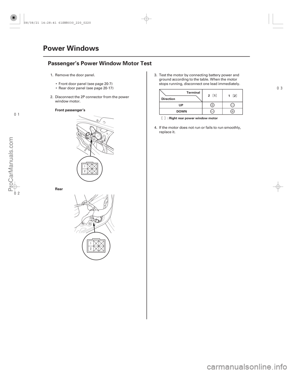
Front passenger’s
Rear
22-218 Power Windows
Passenger’s Power Window Motor Test
Terminal
Direction 21
12
UP
DOWN
: Right rear power window motor
1. Remove the door panel.
Front door panel (see page 20-7)
Rear door panel (see page 20-17)
2. Disconnect the 2P connector from the power window motor. 3. Test the motor by connecting battery power and
ground according to the table. When the motor
stops running, disconnect one lead immediately.
4. If the motor does not run or fails to run smoothly, replace it.
08/08/21 14:28:41 61SNR030_220_0220
ProCarManuals.com
DYNOMITE -2009-
Page 2169 of 2893
����
Driver’s Switch Front Passenger’s Switch
Left Rear Switch
Right Rear Switch
22-219
Power Window Master Switch Test/Replac")
���
��������
���
����
�(�#�'���������������������������
�����������)����
Driver’s Switch Front Passenger’s Switch
Left Rear Switch
Right Rear Switch
22-219
Power Window Master Switch Test/Replacement
A
B
A Main
Switch
Terminal
Position 1
OFF ON
OFF ON
OFF ON
OFF
UP
DOWN 2
3
12
Main
Switch Terminal
Position 20
OFF ON
OFF ON
OFF ON
OFF
UP
DOWN 21 22 12
Main
Switch Terminal
Position 13
OFF ON
OFF ON
OFF ON
OFF
UP
DOWN 14 15 12
1. Carefully pry out the power window master switch
(A).
2. Disconnect the 22P connector (B) from the power window master switch.
3. Check for continuity between the terminals in each switch position according to the tables.
The driver’s switch is combined with the control
unit, so you cannot isolate the switch to test it.
Instead, run the power window master switch input
test procedures (see page 22-214). If the tests are
normal, the driver’s switch must be faulty. Replace
the switch. 4. If the continuity is not as specified, remove the
screws and replace the switch.
5. Install the power window master switch in the reverse order of removal.
08/08/21 14:28:41 61SNR030_220_0221
ProCarManuals.com
DYNOMITE -2009-
Page 2170 of 2893
���
��������
����
�(�#�'���������������������������
�����������)���
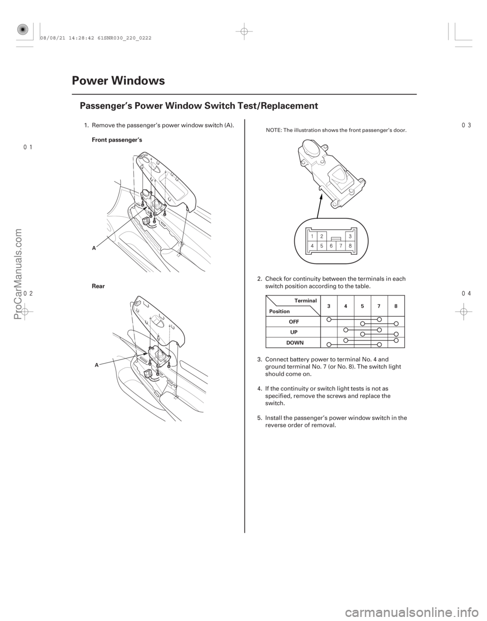
Front passenger’s
Rear
22-220
Power Windows
Passenger’s Power Window Switch Test/Replacement
A
A Terminal
Position 34578
OFF UP
DOWN
1. Remove the passenger’s power window switch (A).
2. Check for continuity between the terminals in eachswitch position according to the table.
3. Connect battery power to terminal No. 4 and ground terminal No. 7 (or No. 8). The switch light
should come on.
4. If the continuity or switch light tests is not as specified, remove the screws and replace the
switch.
5. Install the passenger’s power window switch in the reverse order of removal.NOTE: The illustration shows the front passenger’s door.
08/08/21 14:28:42 61SNR030_220_0222
ProCarManuals.com
DYNOMITE -2009-
Page 2238 of 2893
���
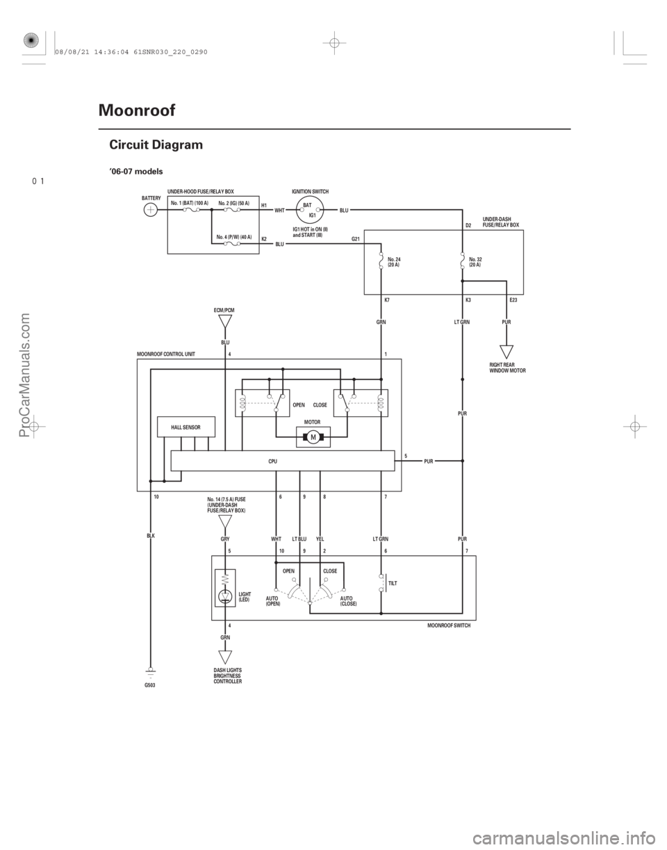
�(�#�'���������������������������������������)���� ’06-07 models
22-288Moonroof
Circuit Diagram
No. 24
(20 A)
IGNITION SWITCH
BATIG1
WHT
BLU
No. 2 (IG) (50 A)
BATTERY
No. 1 (BAT) (100 A)
(20 A)
D2
G21
E23
K3
K7
YEL
WHT
(CLOSE)
(OPEN) PUR
PUR PUR
LT GRN PUR
5
AUTO
AUTO
MOONROOF CONTROL UNIT
6
10OPEN CLOSE
HALL SENSOR
ECM/PCM
4
BLU GRN
No. 4 (P/W) (40 A)
1
10 7
8
9
7
LT BLU
CPU
MOONROOF SWITCH
BLU
G503 BLK
GRY
5 6
2
9 LT GRN
4
GRN LIGHT
(LED)
TILT
MOTOR
CLOSE
OPEN No. 32
UNDER-HOOD FUSE/RELAY BOX
RIGHT REAR
WINDOW MOTOR
No. 14 (7.5 A) FUSE
(UNDER-DASH
FUSE/RELAY BOX)
DASH LIGHTS
BRIGHTNESS
CONTROLLER UNDER-DASH
FUSE/RELAY BOX
IG1 HOT in ON (II)
and START (III)
H1
K2
08/08/21 14:36:04 61SNR030_220_0290
ProCarManuals.com
DYNOMITE -2009-
Page 2239 of 2893
����
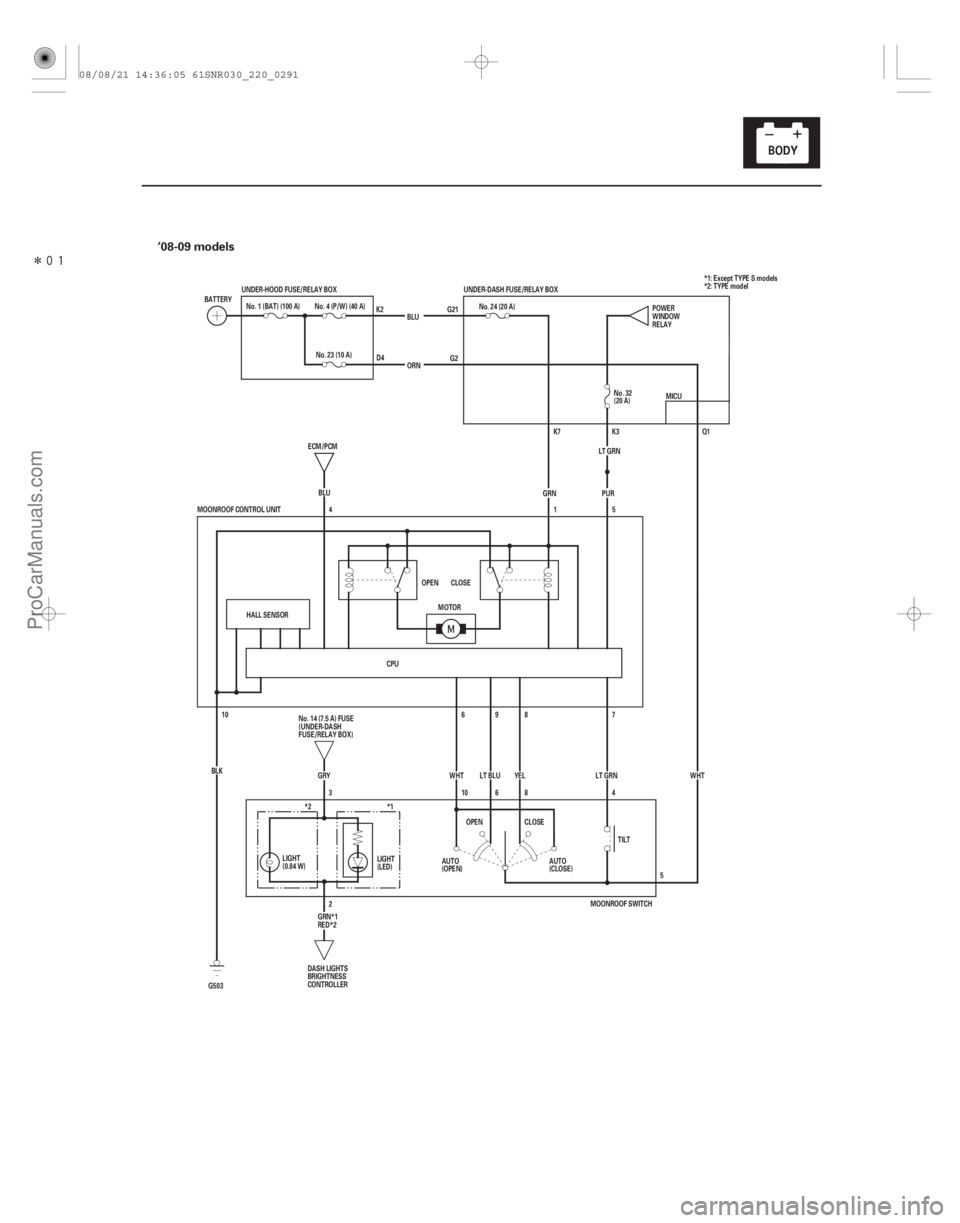
�(�#�'���������������������������������������)���� ’08-09 models
22-289
BLU
No. 4 (P/W) (40 A)
BATTERY
No. 1 (BAT) (100 A)
(20 A)
G2
G21
Q1
K7
YEL
WHT
(CLOSE)
(OPEN) WHT
PUR
LT GRN
AUTO
AUTO
MOONROOF CONTROL UNIT
6
10OPEN CLOSE
HALL SENSOR
ECM/PCM
4
BLU
GRN
1
10 7
8
9
5
LT BLU
CPU ORN
G503 BLK
GRY
3 4
8
6 LT GRN
2 TILT
MOTOR
CLOSE
OPEN No. 32
UNDER-HOOD FUSE/RELAY BOX
No. 14 (7.5 A) FUSE
(UNDER-DASH
FUSE/RELAY BOX)DASH LIGHTS
BRIGHTNESS
CONTROLLER K2
D4 No. 24 (20 A)
5POWER
WINDOW
RELAY
MICU
UNDER-DASH FUSE/RELAY BOX
K3
LIGHT
(LED)
(0.84 W) LIGHT *1: Except TYPE S models
*2: TYPE model
No. 23 (10 A)
*2 *1
MOONROOF SWITCH
GRN*1
RED*2
08/08/21 14:36:05 61SNR030_220_0291
ProCarManuals.com
DYNOMITE -2009-