Page 705 of 2893

PCS (YEL/BLU)
EVAP CANISTER PURGE VALVE
2P CONNECTOR
IG1 (BLK/YEL)
EVAP CANISTER PURGE VALVE
2P CONNECTOR
11. Ju")
��������
�µ
�µ �µ
�µ
YES
NO YES
NO
11-376EVAP System
DTC Troubleshooting (cont’d)
PCS (YEL/BLU)
EVAP CANISTER PURGE VALVE
2P CONNECTOR
IG1 (BLK/YEL)
EVAP CANISTER PURGE VALVE
2P CONNECTOR
11. Jump the SCS line with the HDS.
12. Disconnect ECM/PCM connector B (44P).
13. Check for continuity between EVAP canister purge
valve 2P connector terminal No. 2 and body ground.
Repair short in the wire between the EVAP
canister purge valve and the ECM/PCM (B3), then
go to step 24.
Go to step 30.
14. Turn the ignition switch to LOCK (0).
15. Disconnect the EVAP canister purge valve 2P connector.
16. Turn the ignition switch to ON (II). 17. Measure the voltage between EVAP canister purge
valve 2P connector terminal No. 1 and body ground.
Go to step 18.
Repair open in the wire between the EVAP
canister purge valve and the No. 3 ALTERNATOR
(10 A) fuse in the under-dash fuse/relay box, then
go to step 24.
18. Turn the ignition switch to LOCK (0).
19. Jump the SCS line with the HDS.
20. Disconnect ECM/PCM connector B (44P).
Wire side of female terminals Wire side of female terminals
Is there continuity?
Is there battery voltage?
08/08/21 14:32:33 61SNR030_110_0376
ProCarManuals.com
DYNOMITE -2009-
Page 781 of 2893
�
�
�
���
��
����
13-10Manual Transmission
Transmission Removal (cont’d)
A
B
B
B
A
B A
B
C
DB
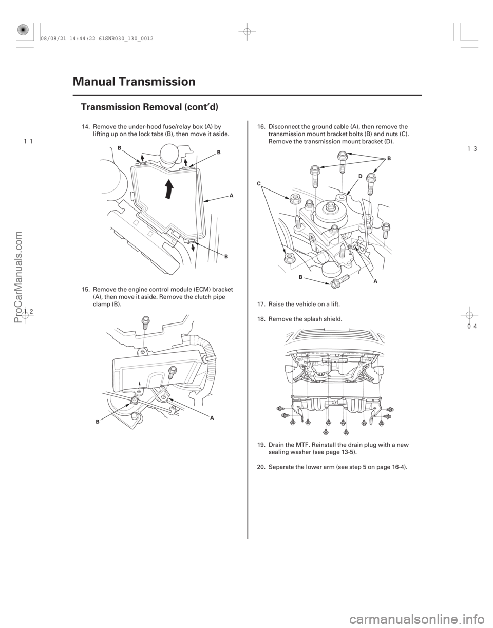
14. Remove the under-hood fuse/relay box (A) by
lifting up on the lock tabs (B), then move it aside.
15. Remove the engine control module (ECM) bracket (A), then move it aside. Remove the clutch pipe
clamp (B). 16. Disconnect the ground cable (A), then remove the
transmission mount bracket bolts (B) and nuts (C).
Remove the transmission mount bracket (D).
17. Raise the vehicle on a lift.
18. Remove the splash shield.
19. Drain the MTF. Reinstall the drain plug with a new sealing washer (see page 13-5).
20. Separate the lower arm (see step 5 on page 16-4).
08/08/21 14:44:22 61SNR030_130_0012
ProCarManuals.com
DYNOMITE -2009-
Page 790 of 2893
�
��
��������
����
13-19
A
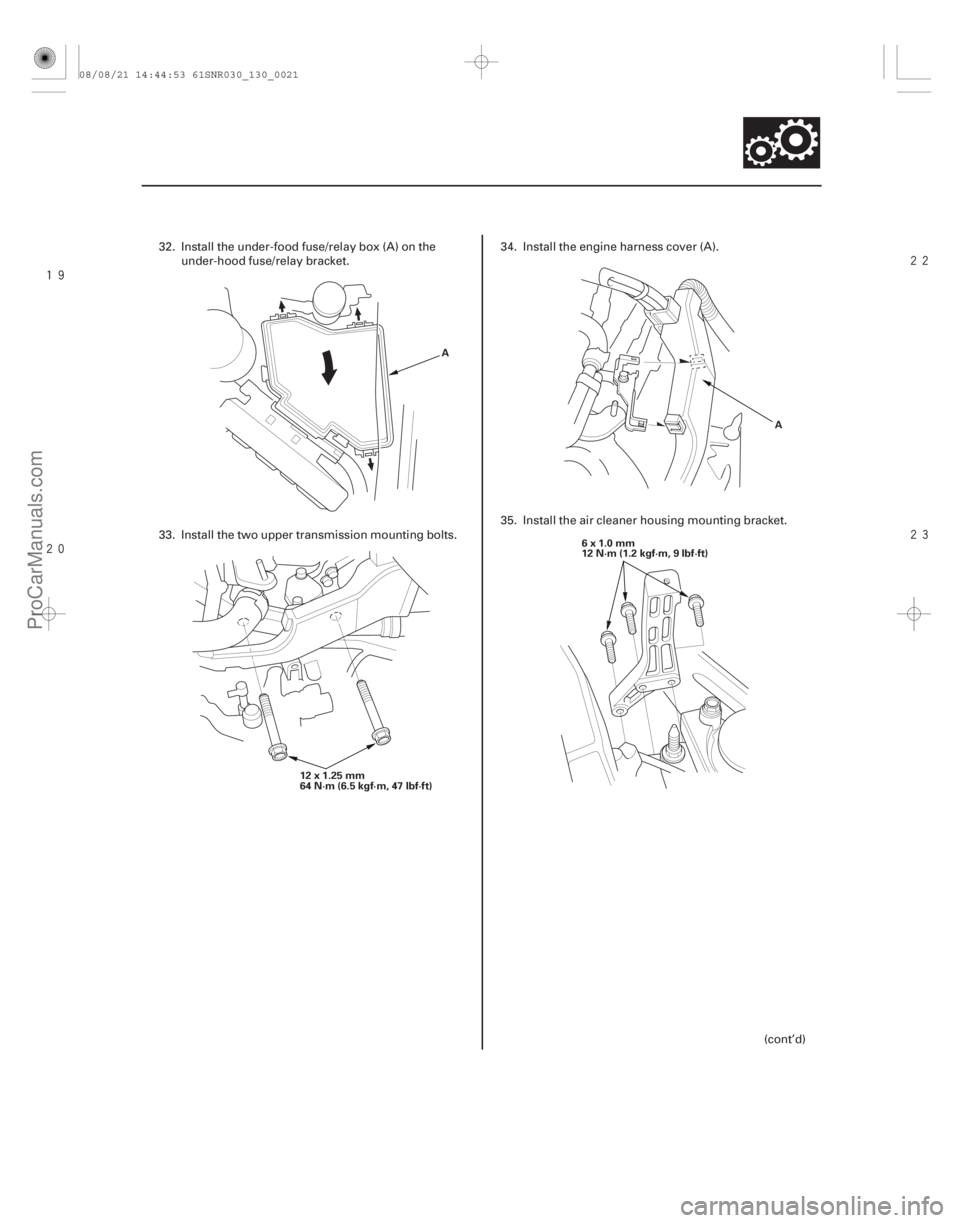
12 x 1.25 mm
64N·m(6.5kgf·m,47lbf·ft) A
6x1.0mm
12 N·m (1.2 kgf·m, 9 lbf·ft)
32. Install the under-food fuse/relay box (A) on the under-hood fuse/relay bracket.
33. Install the two upper transmission mounting bolts. 34. Install the engine harness cover (A).
35. Install the air cleaner housing mounting bracket.
(cont’d)
08/08/21 14:44:53 61SNR030_130_0021
ProCarManuals.com
DYNOMITE -2009-
Page 840 of 2893
����
How to Troubleshoot Circuits at the ECM
Connectors
13-71
Reverse Lockout System
General Troubleshooting Information")
�Ø�Ú�Ó
���
����
����
����
�(�#�'��������� �����
�����������������������)����
How to Troubleshoot Circuits at the ECM
Connectors
13-71
Reverse Lockout System
General Troubleshooting Information
A
E
A
D
B
C A
D
B
CA
NOTE: The ECM overwrites data and monitors the EVAP
system for up to 30 minutes after the ignition switch is
turned to LOCK (0). Jumping the SCS line after turning
the ignition switch to LOCK (0) cancels this function.
Disconnecting the ECM during this function, without
jumping the SCS line first, can damage the ECM.
1. Jump the SCS line with the HDS.
2. Remove the cover (A).
3. Lift up the under-hood fuse/relay box (D).
4. Remove the coolant reservoir (E). Disconnect ECM connectors A, B, and C.
NOTE: ECM connectors A, B, and C have symbols
(A= , B= , C= ) embossed on them for
identification. 5. When troubleshooting is done at the ECM
connector, use the terminal test port (A) above the
terminal you need to check.
6. Connect one side of the patch cord’s terminals (A) to a commercially available digital multimeter (B),
and connect the other side cord’s terminals (C) to a
commercially available banana jack (Pomona
Electronics Tool No. 3563 or equivalent) (D).
7. Gently contact the pin probe (male) at the terminal test port from the terminal side. Do not force the
tips into the terminals.
For accurate results, always use the pin probe (male).
To prevent damage to the c onnector
terminals, do not insert test equipment
probes, paper clips, or other substitutes as
they can damage the terminals. Damaged
terminals cause a poor connection and an
incorrect measurement.
Do not puncture the insulation on a wire. Punctures can cause poor or intermittent
electrical connections.
08/08/21 14:46:38 61SNR030_130_0073
ProCarManuals.com
DYNOMITE -2009-
Page 843 of 2893
���
�(�#����������������
���
�
�����������������)�����µ
�µ
�µ
�µ
Driver can select reverse gear when vehicle
speed is 20 km/h (12 mph) or mor")
����
�(�#�'���������������
���
�
�����������������)���
�(�#�'���������������
���
�
�����������������)�����µ
�µ
�µ
�µ
Driver can select reverse gear when vehicle
speed is 20 km/h (12 mph) or more
YES
NO
YES
NO
13-7413-74 Reverse Lockout System
Circuit Diagram
Symptom Troubleshooting
GRN/BLKYEL
1 2
BLK/YEL BLU
IG1
BAT WHT
BATTERY
UNDER-HOOD
FUSE/RELAY
BOX
IGNITION
SWITCH
IG1HOTinON(II)
and START (III)
UNDER-DASH
FUSE/RELAY
BOX
REVERSE
LOCKOUT
SOLENOID
No. 1
(100 A)
No. 3
(10 A) No. 2
(50 A)
GRN
ECM A27 RVS
NOTE:
When checking if the transmission will shift to reverse while the wheels are being driven forward,
raise the vehicle on a lift, make sure it is securely
supported, and allow the front wheels to rotate freely.
Do not release the clutch pedal if you can select reverse gear while the wheels are driven forward.
When the vehicle is on a lift, and you make the wheels rotate, turn off the VSA system by the VSA
OFF switch.
1. Turn the ignition switch to LOCK (0).
2. Check the No. 3 (10 A) fuse in the under-dash fuse/ relay box.
Reinstallthefuse,thengotostep3.
Install a new No. 3 (10 A) fuse, and recheck. If
the fuse continues to blow, check for short to body
ground in the wire between the No. 3 (10 A) fuse in
the under-dash fuse/relay box and the r everse
lockout solenoid.
3. Test-drive the vehicle.
4. Check for fuel and emissions system’s DTC with the HDS.
Go to the indicated DTC’s troubleshooting.
Go to step 5.
IsthefuseOK?
Ar e t her e any DT Cs st or ed i n t he f uel andemi ssi ons?
08/08/21 14:46:39 61SNR030_130_0076
ProCarManuals.com
DYNOMITE -2009-
Page 844 of 2893
 ECM CONNECTOR A (44P)
RVS (GRN) RVS (GRN/BLK)
REVERSE LOCKOUT SOLENOID 2P CONNECTO")
����
�����
�µ
�µ �µ
�µ
�µ
�µ
YES
NO
YES
NO
YES
NO
13-75
REVERSE LOCKOUT SOLENOID 2P CONNECTOR
IG1 (BLK/YEL) ECM CONNECTOR A (44P)
RVS (GRN) RVS (GRN/BLK)
REVERSE LOCKOUT SOLENOID 2P CONNECTOR
5. Turn the ignition switch to LOCK (0).
6. Disconnect the r everse lockout solenoid 2P
connector.
7. Turn the ignition switch to ON (II).
8. Measure the voltage between reverse lockout solenoid 2P connector terminal No. 2 and body
ground.
Go to step 9.
Repair open in the wire between No. 3 (10 A)
fuse in the under-dash fuse/relay box and the
reverse lockout solenoid.
9. Turn the ignition switch to LOCK (0).
10. Jump the SCS line with the HDS.
11. Disconnect ECM connector A (44P). 12. Check for continuity between reverse lockout
solenoid 2P connector terminal No. 1 and ECM
connector A (44P) terminal No. 27.
Go to step 13.
Repair open in the wire between the reverse
lockout solenoid and the ECM.
13. Do the reverse lockout solenoid test (see page 13-77).
Check for loose terminals or poor
connections at the ECM. If necessary, update the
ECM if it does not have the latest software
(see page 11-227), or substitute a known- good ECM
(see page 11-7), then recheck. If the symptom goes
away with a known-good ECM, replace the original
ECM (see page 11-228).
Repair or replace the reverse lockout solenoid
(see page 13-77).
Wire side of female terminals Terminal side of female terminals
Wire side of female terminals
Is there battery voltage? Is there continuity?
I s t he r ev er se l ock out sol enoi d OK ?
08/08/21 14:46:39 61SNR030_130_0077
ProCarManuals.com
DYNOMITE -2009-
Page 856 of 2893
�
�
�
���
��
�
��
13-87
A
B
B
B
A
B A
B
C D
B
14. Remove the under-hood fuse/relay box (A) by lifting up on the lock tabs (B), then move it aside.
15. Remove the engine control module (ECM) bracket (A), then move it aside. Remove the clutch line
clamp (B). 16. Disconnect the ground cable (A), then remove the
transmission mount bracket bolts (B) and nuts (C).
Remove the transmission mount bracket (D).
17. Raise the vehicle on a lift.
18. Remove the splash shield.
19. Drain the MTF. Reinstall the drain plug with a new sealing washer (see page 13-82).
20. Separate the lower arm (see step 5 on page 16-4).
(cont’d)
08/08/21 14:47:22 61SNR030_130_0089
ProCarManuals.com
DYNOMITE -2009-
Page 864 of 2893
������
�� ����
����
13-95
A
12x1.25mm
64 N·m
(6.5 kgf·m,
47 lbf·ft)
10x1.25mm
38 N·m
(3.9 kgf·m,
28 lbf·ft)
A
B
A
27. Tighten the front mount mounting bolt (A).
28. Install the splash shield.
29. Lower the vehicle on the lift
30. Remove the engine support hanger and the enginehanger adapter from the engine. 31. Install the engine control module (ECM) bracket (A),
then install the clutch pipe clamp (B).
32. Install the under-food fuse/relay box (A) on the under-hood fuse/relay bracket.
(cont’d)
08/08/21 14:47:29 61SNR030_130_0097
ProCarManuals.com
DYNOMITE -2009-