Page 1024 of 2893

INPUT SHAFT (MAINSHAFT)
SPEED SENSOR CONNECTOR
VCC2 (YEL/BLU)
INPUT SHAFT")
����
����
�����
�µ
�µ
�µ
�µ �µ
�µ
YES
NO
YES
NO YES
NO
14-108Automatic Transmission
DTC Troubleshooting (cont’d)
INPUT SHAFT (MAINSHAFT)
SPEED SENSOR CONNECTOR
VCC2 (YEL/BLU)
INPUT SHAFT (MAINSHAFT)
SPEED SENSOR CONNECTOR NM (WHT/RED) INPUT SHAFT (MAINSHAFT)
SPEED SENSOR CONNECTOR
NM (WHT/RED)
12. Measure the voltage between input shaft(mainshaft) speed sensor connector terminal No. 1
and body ground.
Go to step 13.
Go to step 19.
13. Measure the voltage between input shaft (mainshaft) speed sensor connector terminal No. 2
and body ground.
Replace the input shaft (mainshaft) speed
sensor (see page 14-227), then go to step 23.
Go to step 14. 14. Turn the ignition switch to LOCK (0).
15. Jump the SCS line with the HDS.
16. Disconnect PCM connector B (44P).
17. Check for continuity between input shaft
(mainshaft) speed sensor connector terminal No. 2
and body ground.
Repair short to body ground in the wire
between PCM connector terminal B17 and the input
shaft (mainshaft) speed sensor, then go to step 23.
Go to step 18.
Wire side of female terminals
Wire side of female terminals Wire side of female terminals
Is t her e about 5 V ?
Is t her e about 5 V ? Is there continuity?
08/08/21 14:41:06 61SNR030_140_0110
ProCarManuals.com
DYNOMITE -2009-
Page 1025 of 2893

SPEED SENSOR
CONNECTOR
PCM CONNECTOR B (44P)
NM (WHT/RED) NM
(WHT/RED) INPUT SHAFT
(MAINSHAFT)
SPEED SENSOR
CONNECTOR
VCC2 (YEL/BL")
��������
�µ
�µ
�µ
�µ
YES
NO
YES
NO
14-109
INPUT SHAFT
(MAINSHAFT)
SPEED SENSOR
CONNECTOR
PCM CONNECTOR B (44P)
NM (WHT/RED) NM
(WHT/RED) INPUT SHAFT
(MAINSHAFT)
SPEED SENSOR
CONNECTOR
VCC2 (YEL/BLU)
PCM CONNECTOR B (44P)
VCC2 (YEL/BLU)
18. Check for continuity between PCM connector terminal B17 and input shaft (mainshaft) speed
sensor connector terminal No. 2.
Go to step 29.
Repair open in the wire between PCM
connector terminal B17 and the input shaft
(mainshaft) speed sensor, then go to step 23. 19. Turn the ignition switch to LOCK (0).
20. Jump the SCS line with the HDS.
21. Disconnect PCM connector B (44P).
22. Check for continuity between PCM connector
terminal B18 and input shaft (mainshaft) speed
sensor connector terminal No. 1.
Go to step 29.
Repair open in the wire between PCM
connector terminal B18 and the input shaft
(mainshaft) speed sensor, then go to step 23.
(cont’d)
Wire side of
female terminals
Terminal side of
female terminals
Wire side of
female terminals
Terminal side of
female terminals
Is there continuity?
Is there continuity?
08/08/21 14:41:07 61SNR030_140_0111
ProCarManuals.com
DYNOMITE -2009-
Page 1027 of 2893
����
�µ
�µ �µ
�µ
DTC P0721:
DTC P0722:
YES
NO YES
NO
14-111
PCM CONNECTOR C (44P)
LG2 (BRN/YEL)
LG1 (BRN/YEL)
Problem in Output Shaft
(Countersha")
���
�(�#�'�������
� �����
���������������
�������)����
�µ
�µ �µ
�µ
DTC P0721:
DTC P0722:
YES
NO YES
NO
14-111
PCM CONNECTOR C (44P)
LG2 (BRN/YEL)
LG1 (BRN/YEL)
Problem in Output Shaft
(Countershaft) Speed Sensor Circuit
Problem in Output Shaft
(Countershaft) Speed Sensor Circuit (No
Signal Input)
NOTE:
Before you troubleshoot, record all freeze data and any on-board snapshot with the HDS, and review
General Troubleshooting Information (see page 14-3).
This code is caused by an electrical circuit problem and cannot be caused by a mechanical problem in the
transmission.
1. Check for proper output shaft (countershaft) speed sensor installation (see page 14-227).
2. Turn the ignition switch to ON (II).
3. Clear the DTC with the HDS.
4. Raise the front of the vehicle, make sure it is securely supported, and allow the front wheels to
rotate freely, or raise the vehicle on a lift.
5. Start the engine, disable the VSA by pressing the VSA OFF switch (if equipped), run the vehicle with
the shift lever in D and the engine speed 2,000 rpm
or higher, for at least 10 seconds. Slow down and
stop the wheels.
6. Monitor the OBD STATUS for P0721 or P0722 in the DTCs MENU with the HDS.
Go to step 7.
If the HDS indicates PASSED, intermittent
failure, the system is OK at this time. Check for
poor connections or loose terminals between the
output shaft (countershaft) speed sensor and the
PCM. If the HDS indicates NOT COMPLETED, go to
step 5. 7. Turn the ignition switch to LOCK (0).
8. Jump the SCS line with the HDS.
9. Disconnect PCM connector C (44P).
10. Check for continuity between PCM connector terminal C40 and body ground, and between PCM
connector terminal C44 and body ground.
Go to step 11.
Repair open in the wires between PCM
connector terminals C40, C44, and body ground
(G101) (see page 22-16), or repair poor body
ground (G 101), then go to step 26.
(cont’d)
Terminal side of female terminals
Does the HDS ind icate F AILED? Is there continuity?
08/08/21 14:41:07 61SNR030_140_0113
ProCarManuals.com
DYNOMITE -2009-
Page 1028 of 2893

OUTPUT SHAFT (COUNTERSHAFT)
SPEED SENSOR CONNECTOR
VCC1 (YEL/RED) OUTPUT SHAFT
(COUNTERSHAFT)
SPEED S")
��������
�µ
�µ �µ
�µ
YES
NO YES
NO
14-112Automatic Transmission
DTC Troubleshooting (cont’d)
OUTPUT SHAFT (COUNTERSHAFT)
SPEED SENSOR CONNECTOR
VCC1 (YEL/RED) OUTPUT SHAFT
(COUNTERSHAFT)
SPEED SENSOR
CONNECTOR
VCC1 (YEL/RED)
PCM CONNECTOR C (44P)
VCC1
(YEL/RED)
11. Connect PCM connector C (44P).
12. Disconnect the output shaft (countershaft) speed sensor connector.
13. Turn the ignition switch to ON (II).
14. Measure the voltage between output shaft (countershaft) speed sensor connector terminal
No. 1 and body ground.
Go to step 19.
Go to step 15. 15. Turn the ignition switch to LOCK (0).
16. Jump the SCS line with the HDS.
17. Disconnect PCM connector C (44P).
18. Check for continuity between PCM connector
terminal C13 and output shaft (countershaft) speed
sensor connector terminal No. 1.
Go to step 32.
Repair open in the wire between PCM
connector terminal C13 and the output shaft
(countershaft) speed sensor, then go to step 26.
Wire side of female terminals Wire side of
female terminals
Terminal side of
female terminals
Is t her e about 5 V ? Is there continuity?
08/08/21 14:41:08 61SNR030_140_0114
ProCarManuals.com
DYNOMITE -2009-
Page 1029 of 2893
��������
�µ
�µ �µ
�µ
YES
NO
YES
NO
14-113
OUTPUT SHAFT (COUNTERSHAFT)
SPEED SENSOR CONNECTOR
NC (BLK/WHT) SG1 (GRN/WHT) OUTPUT SHAFT (COUNTERSHAFT)
SPEED SENSOR CONNECTOR
NC (BLK/WHT)
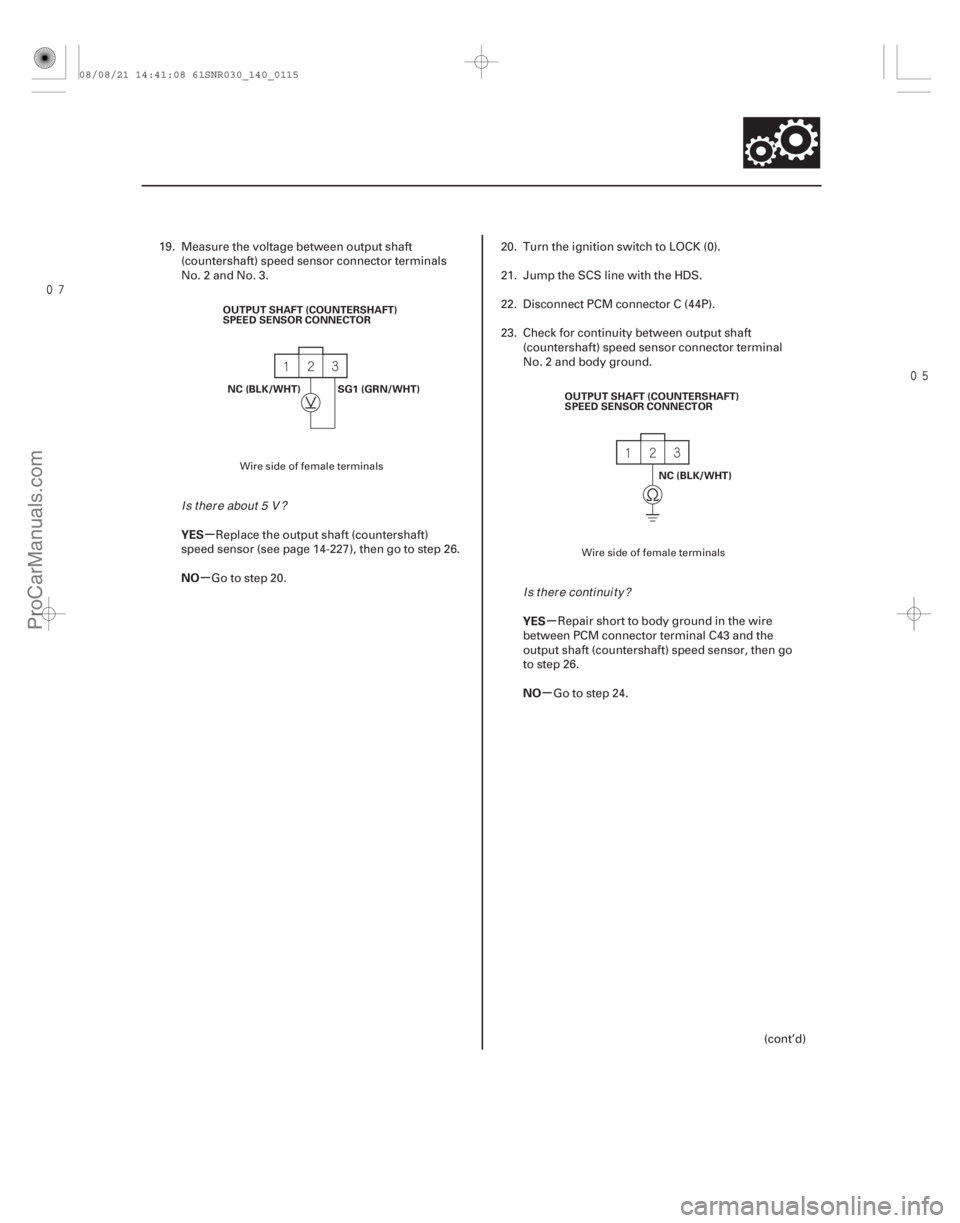
19. Measure the voltage between output shaft(countershaft) speed sensor connector terminals
No. 2 and No. 3.
Replace the output shaft (countershaft)
speed sensor (see page 14-227), then go to step 26.
Go to step 20. 20. Turn the ignition switch to LOCK (0).
21. Jump the SCS line with the HDS.
22. Disconnect PCM connector C (44P).
23. Check for continuity between output shaft
(countershaft) speed sensor connector terminal
No. 2 and body ground.
Repair short to body ground in the wire
between PCM connector terminal C43 and the
output shaft (countershaft) speed sensor, then go
to step 26.
Go to step 24.
(cont’d)
Wire side of female terminals Wire side of female terminals
Is t her e about 5 V ?Is there continuity?
08/08/21 14:41:08 61SNR030_140_0115
ProCarManuals.com
DYNOMITE -2009-
Page 1032 of 2893
����
�µ
�µ
�µ
�µ �µ
�µ
DTC P0723:
YES
NO
YES
NO YES
NO
14-116Automatic Transmission
DTC Troubleshooting (cont’d)
PCM CONNECTOR C (44P)
LG2 (B")
���
�(�#�'�������
� �����
�����������������������)����
�µ
�µ
�µ
�µ �µ
�µ
DTC P0723:
YES
NO
YES
NO YES
NO
14-116Automatic Transmission
DTC Troubleshooting (cont’d)
PCM CONNECTOR C (44P)
LG2 (BRN/YEL)
LG1 (BRN/YEL)
Output Shaft (Countershaft)
Speed Sensor Intermittent Failure
NOTE:
Before you troubleshoot, record all freeze data and any on-board snapshot with the HDS, and review
General Troubleshooting Information (see page 14-3).
This code is caused by an electrical circuit problem and cannot be caused by a mechanical problem in the
transmission.
1. Turn the ignition switch to ON (II).
2. Clear the DTC with the HDS.
3. Test-drive the vehicle with the shift lever in D, and let the transmission shift through all five gears with
the engine speed at 2,000 rpm or higher.
4. Monitor the OBD STATUS for P0723 in the DTCs MENU with the HDS.
Go to step 5.
If the HDS indicates PASSED, intermittent
failure, the system is OK at this time. Check for
poor connections or loose terminals between the
output shaft (countershaft) speed sensor and the
PCM. If the HDS indicates NOT COMPLETED, go to
step 3.
5. Turn the ignition switch to LOCK (0).
6. Disconnect the output shaft (countershaft) speed sensor connector, and inspect the connector and
connector terminals to be sure they are making
good contact.
Go to step 7.
Repair the connector terminals, then go to
step 23. 7. Jump the SCS line with the HDS.
8. Disconnect PCM connector C (44P).
9. Check for continuity between PCM connector
terminal C40 and body ground, and between PCM
connector terminal C44 and body ground.
Go to step 10.
Repair open in the wires between PCM
connector terminals C40, C44, and body ground
(G101) (see page 22-16), or repair poor body
ground (G 101), then go to step 23.
Terminal side of female terminals
Does the HDS ind icate F AILED?
Ar e t he connect or t er mi nal s OK ? Is there continuity?
08/08/21 14:41:09 61SNR030_140_0118
ProCarManuals.com
DYNOMITE -2009-
Page 1034 of 2893

OUTPUT SHAFT (COUNTERSHAFT)
SPEED SENSOR CONNECTOR
NC (BLK/WHT) OUTPUT SHAFT
(COUNTERSHAFT)
SPEED")
���������
�µ
�µ �µ
�µ
YES
NO YES
NO
14-118Automatic Transmission
DTC Troubleshooting (cont’d)
OUTPUT SHAFT (COUNTERSHAFT)
SPEED SENSOR CONNECTOR
NC (BLK/WHT) OUTPUT SHAFT
(COUNTERSHAFT)
SPEED SENSOR
CONNECTOR
NC
(BLK/WHT)
PCM CONNECTOR C (44P)
NC (BLK/WHT)
14. Turn the ignition switch to LOCK (0).
15. Jump the SCS line with the HDS.
16. Disconnect PCM connector C (44P).
17. Check for continuity between output shaft(countershaft) speed sensor connector terminal
No. 2 and body ground.
Repair short to body ground in the wire
between PCM connector terminal C43 and the
output shaft (countershaft) speed sensor, then go
to step 23.
Go to step 18. 18. Check for continuity between PCM connector
terminal C43 and output shaft (countershaft) speed
sensor connector terminal No. 2.
Go to step 29.
Repair open in the wire between PCM
connector terminal C43 and the output shaft
(countershaft) speed sensor, then go to step 23.
Wire side of female terminals Wire side of
female terminals
Terminal side of
female terminals
Is there continuity? Is there continuity?
08/08/21 14:41:10 61SNR030_140_0120
ProCarManuals.com
DYNOMITE -2009-
Page 1035 of 2893

SPEED SENSOR
CONNECTOR
VCC1 (YEL/RED)
PCM CONNECTOR C (44P)
VCC1
(YEL/RED)
19. Turn the ignition switch to LOCK (0).")
�����µ
�µ �µ
�µ
�µ
�µ
YES
NO YES
NO
YES
NO
14-119
OUTPUT SHAFT
(COUNTERSHAFT)
SPEED SENSOR
CONNECTOR
VCC1 (YEL/RED)
PCM CONNECTOR C (44P)
VCC1
(YEL/RED)
19. Turn the ignition switch to LOCK (0).
20. Jump the SCS line with the HDS.
21. Disconnect PCM connector C (44P).
22. Check for continuity between PCM connector terminal C13 and output shaft (countershaft) speed
sensor connector terminal No. 1.
Go to step 29.
Repair open in the wire between PCM
connector terminal C13 and the output shaft
(countershaft) speed sensor, then go to step 23. 23. Reconnect all connectors.
24. Turn the ignition switch to ON (II).
25. Clear the DTC with the HDS.
26. Test-drive the vehicle with the shift lever in D at
speeds over 20 km/h (12 mph), and let the
transmission shift through all five gears.
27. Check for Temporary DTCs or DTCs with the HDS.
Check for poor connections or loose
terminals between the output shaft (countershaft)
speed sensor and the PCM, then go to step 1.
Go to step 28.
28. Monitor the OBD STATUS for P0723 in the DTCs MENU with the HDS.
Troubleshooting is complete. If any other
Temporary DTCs or DTCs were indicated in step 27,
go to the indicated DTC’s troubleshooting.
If the HDS indicates FAILED, check for poor
connections or loose terminals between the output
shaft (countershaft) speed sensor and the PCM,
then go to step 1. If the HDS indicates NOT
COMPLETED, go to step 26.
(cont’d)
Wire side of
female terminalsTerminal side of
female terminals
Is there continuity? Is DTC P0723 indicated?
Does the HDS ind icate PASSED?
08/08/21 14:42:30 61SNR030_140_0121
ProCarManuals.com
DYNOMITE -2009-