Page 1141 of 2893
 F
E
C
9. Remove the mounting bolts, the harness clampbrackets (A), and A/T clutch pressure control
solenoid valves B and C.
10. Rem")
���������
14-225
AD
BC
A
6x1.0mm
12 N·m (1.2 kgf·m, 8.7 lbf·ft) F
E
C
9. Remove the mounting bolts, the harness clampbrackets (A), and A/T clutch pressure control
solenoid valves B and C.
10. Remove the ATF joint pipes (D), the O-rings (E), and the gasket (F).
11. Check the fluid passage of the solenoid valves for contamination. 12. Connect a jumper wire from the negative battery
terminal to A/T clutch pressure control solenoid
valve C connector terminal No. 2, and connect
another jumper wire from the positive battery
terminal to connector terminal No. 1. Make sure
A/T clutch pressure control solenoid valve C moves.
13. Disconnect one of the jumper wires, and check valve movement at the fluid passage in the valve
body mounting surface. If the valve binds or moves
sluggishly, or if the solenoid valve does not operate,
replace A/T clutch pressure control solenoid valves
BandC.
14. Clean the mounting surfaces and the fluid passages of the A/T clutch pressure control solenoid valve
body and the transmission housing.
15. Install a new gasket on the transmission housing.
NOTE: Be sure to install a new gasket with the blue
side toward the transmission housing.
16. Install the ATF joint pipes, and install new O-rings over the ATF joint pipes.
17. Install A/T clutch pressure control solenoid valves B and C.
18. Check the connectors for rust, dirt, or oil, clean or repair if necessary, then connect the connectors
securely.
19. Install the air cleaner assembly (see page 11-345) and the intake air duct (see page 11-348).
Replace.
Replace.
08/08/21 14:46:49 61SNR030_140_0227
ProCarManuals.com
DYNOMITE -2009-
Page 1142 of 2893
�
��
14-226Automatic Transmission
A/T Clutch Pressure Control Solenoid Valve B and C Replacement
A
D
BC
A
6x1.0mm
12 N·m (1.2 kgf·m, 8.7 lbf·ft)")
������(�#�'�������
���
�����
�����
��������� �����)�
��
14-226Automatic Transmission
A/T Clutch Pressure Control Solenoid Valve B and C Replacement
A
D
BC
A
6x1.0mm
12 N·m (1.2 kgf·m, 8.7 lbf·ft) F
E
1. Remove the intake air duct (see page 11-348) and the air cleaner assembly (see page 11-345).
2. Disconnect the A/T clutch pressure control solenoid valves B and C connectors.
3. Remove the mounting bolts, the harness clamp brackets (A), and A/T clutch pressure control
solenoid valves B and C.
4. Remove the ATF joint pipes (D), the O-rings (E), and the gasket (F). 5. Clean the mounting surface and the fluid passage
of the transmission housing.
6. Install a new gasket on the transmission housing, and install the ATF joint pipes.
NOTE: Be sure to install a new gasket with the blue
side toward the transmission housing.
7. Install new O-rings over the ATF joint pipes.
8. Install new A/T clutch pressure control solenoid valves B and C, and harness clamp brackets.
9. Check the connectors for rust, dirt, or oil, clean or repair if necessary, then connect it securely.
10. Install the air cleaner assembly (see page 11-345) and the intake air duct (see page 11-348).
Replace.
Replace.
08/08/21 14:46:49 61SNR030_140_0228
ProCarManuals.com
DYNOMITE -2009-
Page 1147 of 2893
����
14-231
ATF Level Check
A
A
B
ATF
NOTE: Keep all foreign particles out of the transmission. 1. Park the vehicle on the level ground")
�µ
���
���
����
�(�#�'�������
���
�����������
�������
�"�����)����
14-231
ATF Level Check
A
A
B
ATF
NOTE: Keep all foreign particles out of the transmission. 1. Park the vehicle on the level ground.
2. Warm up the engine to normal operating temperature (the radiator fan comes on), and turn
the engine off. Do not allow the engine to warm up
more than two cycles of the cooling fan.
NOTE: Check the ATF level within 60 90 seconds
after turning the engine off. Higher ATF level may
be indicated if the radiator fan comes on twice or
more.
3. Remove the ATF dipstick (yellow loop) (A), and wipe it with a clean cloth.
4. Insert the dipstick into the transmission.
5. Remove the dipstick and check the ATF level. It should be between the upper mark (A) and the
lower mark (B). 6. If the ATF level is below the lower mark, check for
fluid leaks at the transmission, the hoses, and the
line joints. If a problem is found, fix it before f illing
the transmission with ATF.
NOTE: If the vehicle is driven when the ATF level is
below the lower mark, one or more of these
symptoms may occur: The transmission damage.
The vehicle may not move in any gear.
The vehicle may accelerates poorly, and flares when starting off in D, S, and R.
Vibration when the engine is idling.
7. If the ATF level is above the upper mark, drain the
ATF to proper level (see step 3 on page 14-232).
NOTE: If the vehicle is driven when the ATF level is
above the upper mark, the vehicle may creep
forward while in N, or have problems shifting.
8. If necessary, fill the transmission with ATF through the dipstick hole to bring the fluid level to midway
between the upper mark and the lower mark of the
dipstick. Do not fill the fluid above the upper mark.
Always use genuine Acura ATF-Z1 automatic
transmission fluid (ATF). Using a non-Acura ATF
can affect shift quality.
9. Insert the dipstick back into the transmission with the letters ‘‘ATF’’ pointing toward the front of the
vehicle.
08/08/21 14:46:52 61SNR030_140_0233
ProCarManuals.com
DYNOMITE -2009-
Page 1148 of 2893
����
Automatic Transmission Fluid Capacity:
2.9 L (3.1 US qt) at change
6.5 L (6.9 US qt) at overhaul
14-232 Automatic Transmission
ATF R")
����
���� ����
�(�#�'�������
���
�����������
�������
� �����)����
Automatic Transmission Fluid Capacity:
2.9 L (3.1 US qt) at change
6.5 L (6.9 US qt) at overhaul
14-232 Automatic Transmission
ATF Replacement
A
18 x 1.5 mm
49 N·m
(5.0 kgf·m,
36 lbf·ft)
B
ATF
A
NOTE: Keep all foreign particles out of the transmission. 1. Park the vehicle on the level ground.
2. Warm up the engine to normal operating temperature (the radiator fan comes on), and turn
the engine off.
3. Remove the drain plug (A), and drain the automatic transmission fluid (ATF).
4. Reinstall the drain plug with a new sealing washer (B).
5. Refill the transmission with ATF into the dipstick hole to bring the fluid level between the upper
mark and the lower mark of the dipstick. Always
use Acura ATF-Z1 automatic transmission fluid
(ATF). Using a non-Acura ATF can affect shift
quality.
6. Check that the ATF level is between the upper mark
and the lower mark of the dipstick.
7. Insert the dipstick back into the transmission with the letters ‘‘ATF’’ pointing toward the front of the
vehicle. 8. If the maintenance minder required to replace the
ATF, reset the maintenance minder (see page 3-4),
and this procedure is complete. If the maintenance
minder did not require you to replace the ATF, go
to step 9.
9. Connect the HDS to the DLC (A) located under the driver’s side of the dashboard.
10. Turn the ignition switch to ON (II). Make sure the HDS communicates with the PCM. If it does not, go
to the DLC circuit troubleshooting (see page
11-204).
11. Select BODY ELECTRICAL with the HDS.
12. Select ADJUSTMENT in the GAUGES MENU with the HDS.
13. Select RESET in the MAINTENANCE MINDER MENU with the HDS.
14. Select RESETTING THE ATF with the HDS.
NOTE: If you changed the engine oil at the same
time with the ATF, select RESETTING THE ENGINE
OIL LIFE AND ATF with the HDS instead.
Replace.
08/08/21 14:46:53 61SNR030_140_0234
ProCarManuals.com
DYNOMITE -2009-
Page 1278 of 2893
 6x1.0mm
12 N·m
(1.2 kgf·m, 8.7 lbf·ft)
A D
B C
E D
B
C A
6x1.0mm
12 N·m (1.2 kgf·m, 8.7 lbf·ft)
25. Install the trans")
�
��
�
���
��
�����
14-353
A
B C
6x1.0mm
12 N·m (1.2 kgf·m, 8.7 lbf·ft) 6x1.0mm
12 N·m
(1.2 kgf·m, 8.7 lbf·ft)
A D
B C
E D
B
C A
6x1.0mm
12 N·m (1.2 kgf·m, 8.7 lbf·ft)
25. Install the transmission range switch (A) gently on the selector control shaft (B) while holding it in the
N position using the 2.0 mm (0.08 in.) blade (C).
26. Tighten the bolts on the transmission range switch while you continue to hold it in the N position. Do
not move the transmission range switch when
tightening the bolts. Remove the feeler gauge. 27. Connect the transmission range switch connector
(A) securely, then install the harness clamps (B) on
the clamp bracket (C).
28. Install the transmission range switch cover (D).
29. Install a new gasket (B) on the transmission housing, and install the ATF pipe (C) and the ATF
joint pipes (D).
NOTE: Be sure to install a new gasket with the blue
side toward the transmission housing.
30. Install new O-rings (E) over the ATF joint pipes, and install A/T clutch pressure control solenoid valve A.
(cont’d)
Replace.
08/08/21 14:52:38 61SNR030_140_0355
ProCarManuals.com
DYNOMITE -2009-
Page 1279 of 2893
�����
��
�
��
14-354Transmission End Cover
End Cover Installation (cont’d)
A
D
E
B
C
F6x1.0mm
12 N·m
(1.2 kgf·m,
8.7 lbf·ft)
F
B
28N·m(2.9kgf·m,21lbf·ft)
E
28 N·m (2.9 kgf·m, 21 lbf·ft) C
C A
D F
F
A
B
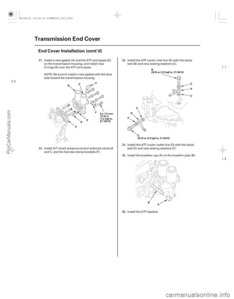
31. Install a new gasket (A) and the ATF joint pipes (D)
on the transmission housing, and install new
O-rings (E) over the ATF joint pipes.
NOTE: Be sure to install a new gasket with the blue
side toward the transmission housing.
32. Install A/T clutch pressure control solenoid valves B and C, and the harness clamp brackets (F). 33. Install the ATF cooler inlet line (A) with the banjo
bolt (B) and new sealing washers (C).
34. Install the ATF cooler outlet line (D) with the banjo bolt (E) and new sealing washers (F).
35. Install the breather cap (A) on the breather pipe (B).
36. Install the ATF dipstick.
08/08/21 14:52:39 61SNR030_140_0356
ProCarManuals.com
DYNOMITE -2009-
Page 1300 of 2893
����
��������
����
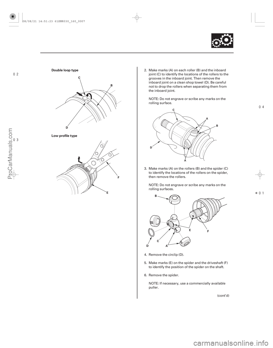
Double loop type
Low profile type
16-7
C
B
D
F
E
A
D E
B
C F
A
A B
D C
2. Make marks (A) on each roller (B) and the inboard
joint (C) to identify the locations of the rollers to the
grooves in the inboard joint. Then remove the
inboard joint on a clean shop towel (D). Be careful
not to drop the rollers when separating them from
the inboard joint.
NOTE: Do not engrave or scribe any marks on the
rolling surface.
3. Make marks (A) on the rollers (B) and the spider (C) to identify the locations of the rollers on the spider,
then remove the rollers.
NOTE: Do not engrave or scribe any marks on the
rolling surfaces.
4. Remove the circlip (D).
5. Make marks (E) on the spider and the driveshaft (F) to identify the position of the spider on the shaft.
6. Remove the spider. NOTE: If necessary, use a commercially available
puller. (cont’d)
08/08/21 14:51:23 61SNR030_160_0007
ProCarManuals.com
DYNOMITE -2009-
Page 1302 of 2893
����
����� �
�
�
��
16-9
A
B
C
B
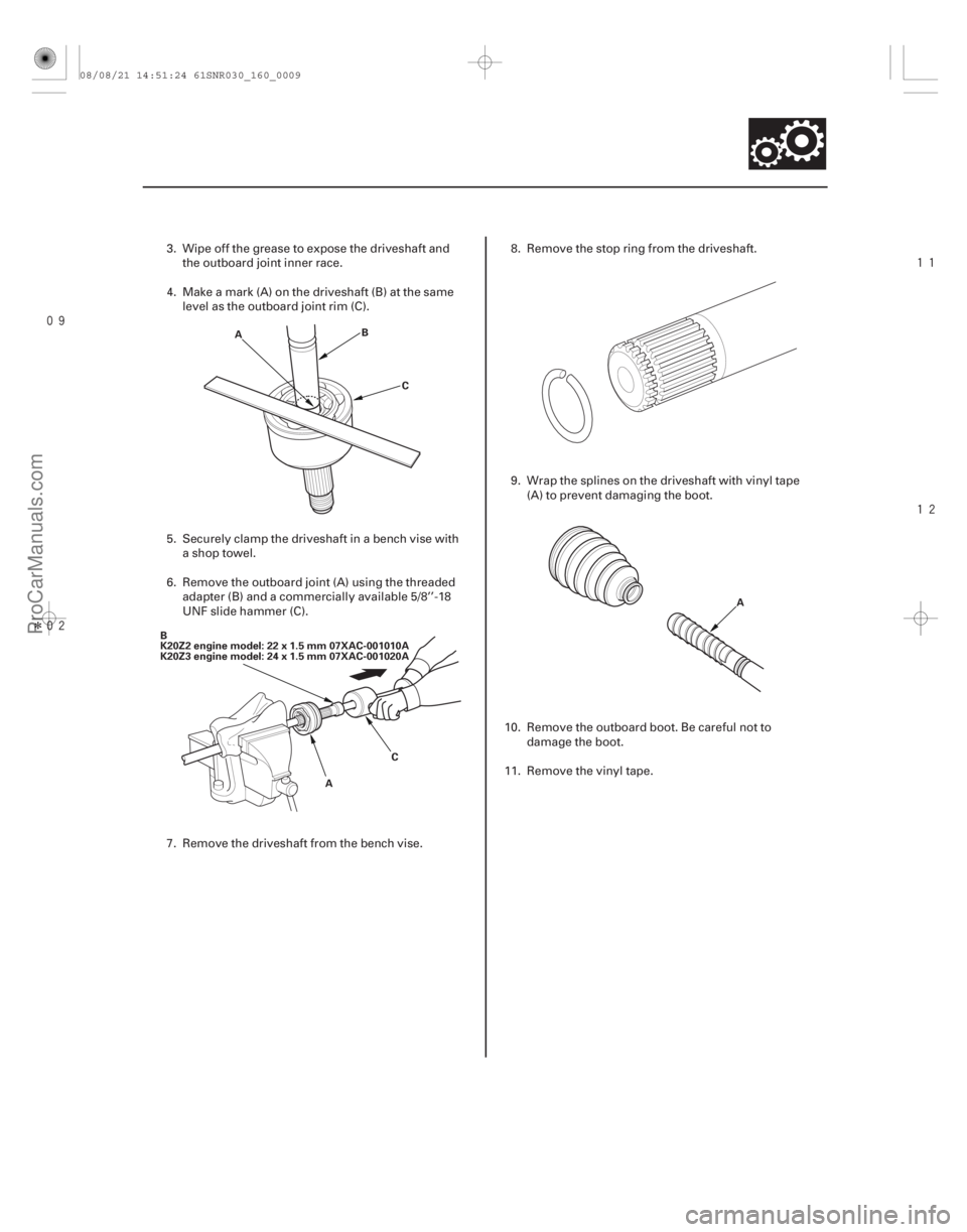
K20Z2 engine model: 22 x 1.5 mm 07XAC-001010A
K20Z3 engine model: 24 x 1.5 mm 07XAC-001020A AC A
3. Wipe off the grease to expose the driveshaft and
the outboard joint inner race.
4. Make a mark (A) on the driveshaft (B) at the same level as the outboard joint rim (C).
5. Securely clamp the driveshaft in a bench vise with a shop towel.
6. Remove the outboard joint (A) using the threaded adapter (B) and a commercially available 5/8’’-18
UNF slide hammer (C).
7. Remove the driveshaft from the bench vise. 8. Remove the stop ring from the driveshaft.
9. Wrap the splines on the driveshaft with vinyl tape
(A) to prevent damaging the boot.
10. Remove the outboard boot. Be careful not to damage the boot.
11. Remove the vinyl tape.
08/08/21 14:51:24 61SNR030_160_0009
ProCarManuals.com
DYNOMITE -2009-