Page 874 of 2893

����
�(�#�'���������������
���������������
�"�����)����
13-105
Change Lever Assembly Disassembly/Reassembly
DUST COVEROIL SEAL
SHIFT ARM
COVER
SELECT STOP
PLATE DUST SEAL
INTERLOCK
5TH/6TH
SELECT
SPRING WASHER
REVERSE LOCKOUT
SOLENOID (MOLYBDENUM)
1ST/2ND
SELECT
SPRING
SELECT
LOCK CAM A
MBS RETURN
SPRING
CHANGE
LEVER COVER
SHIFT
ARM (MOLYBDENUM)
(MOLYBDENUM)
SELECT LEVER
SELECT
LOCK CAM B
ROLLER
CHANGE LEVER
6x1.0mm
12 N·m
(1.2 kgf·m,
8.7 lbf·ft)
8mm
SPRING
WASHER8mm
SPECIAL BOLT
31 N·m
(3.2 kgf·m,
23 lbf·ft)
MBS ARM
BREATHER CAP
NOTE:
Do not install components if too much time has passed after applying liquid gasket. Instead, remove the old residue, and reapply liquid gasket.
Prior to reassembling, clean all parts in solvent, dry them, and apply grease to the contact surfaces as shown.
Replace.
Replace.
Apply liquid gasket
(08C70-X0331S) to
the sealing surface. Be careful not to damage the dust seal
when installing it.
Turn toward the front of
the vehicle, and install it.
08/08/21 14:47:58 61SNR030_130_0107
ProCarManuals.com
DYNOMITE -2009-
Page 899 of 2893

���
��������
�(�#�'���������������
�����������������"�����)����
Special Tools Required
13-131
Mainshaft Thrust Clearance Adjustment
A
M B
B
A
C A
07GAJ-PG20110
B
07GAJ-PG20130 D
C
Catch adapter 07GAJ-PG20110
Base adapter 07GAJ-PG20130
NOTE:
Take measurement at normal room temperature.
Clean all the parts thoroughly before installation.
1. Remove the 72 mm shim (A) and oil guide plate M from the transmission housing (B).
2. Thoroughly clean the 28 mm spring washer (A) and the 28 mm washer (B) before installing them on the
clutch housing side ball bearing (C).
NOTE: Install the spring washer in the direction
shown.
3. Assemble all of the mainshaft components. NOTE: Refer to the Exploded View, as needed
during the assembly (see page 13-113). 4. Install the mainshaft assembly into the clutch
housing.
5. Place the transmission housing over the mainshaft and onto the clutch housing.
6. Tighten the clutch and transmission housings with several 8 mm bolts.
NOTE: It is not necessary to use sealing agent
between the housing for this procedure.
7. Lightly tap on the mainshaft with a plastic hammer.
8. Attach the catch adapter (A) and the base adapter (B) to the mainshaft as follows:
Back out the catch adapter bolt (C), and loosen the two hex bolts (D).
Fit the catch adapter over the mainshaft so its lip is towards the transmission.
Align the catch adapter lip around the groove at the inside of the mainshaft splines, then tighten
the hex bolts.
9. Fully seat the mainshaft by tapping its end with a plastic hammer.
10. Thread the catch adapter bolt in until it just contacts thewidesurfaceofthebaseadapter.
(cont’d)
08/08/21 14:48:41 61SNR030_130_0133
ProCarManuals.com
DYNOMITE -2009-
Page 910 of 2893
�����
��������
����
�(�#�'���������������
�������
��������� �����)���� Special Tools Required
13-14113-141
Oil Seal Replacement
B
07746-0030100
C
A
B
07746-0030100
C
A A
B
A
B
3. Install new bearings (A) on with the 40 mm inner driver handle (B) and a press. Press on each
bearing until it bottoms. There should be no
clearance between the bearings and the carrier.
NOTE: Place the seal (C) part of the bearing
towards the outside of the differential, and install it. Oil seal driver attachment 07NAD-P20A100
Driver handle, 15 x 135L 07749-0010000
1. Remove the oil seal (A) from the transmission housing (B).
2. Remove the oil seal (A) from the clutch housing (B).
(cont’d)
08/08/21 14:48:57 61SNR030_130_0143
ProCarManuals.com
DYNOMITE -2009-
Page 911 of 2893
�����
��������
����
�(�#�'���������������
�������
��������� �����)���� Special Tools Required
13-14113-141
Oil Seal Replacement
B
07746-0030100
C
A
B
07746-0030100
C
A A
B
A
B
3. Install new bearings (A) on with the 40 mm inner driver handle (B) and a press. Press on each
bearing until it bottoms. There should be no
clearance between the bearings and the carrier.
NOTE: Place the seal (C) part of the bearing
towards the outside of the differential, and install it. Oil seal driver attachment 07NAD-P20A100
Driver handle, 15 x 135L 07749-0010000
1. Remove the oil seal (A) from the transmission housing (B).
2. Remove the oil seal (A) from the clutch housing (B).
(cont’d)
08/08/21 14:48:57 61SNR030_130_0143
ProCarManuals.com
DYNOMITE -2009-
Page 971 of 2893

���
��
�� Regulator Valve
14-55
To TORQUE
CONVERTER
From ATF PUMP
To LUBRICATION and
To RELIEF VALVE
C
B
A
REGULATOR VALVE
ORIFICE
VALVE SPRING
STATOR
TORQUE CONVERTER
REGULATOR VALVE
REGULATOR
SPRING CAP STATOR SHAFT
ARM END STATOR SHAFT
REGULATOR VALVE BODY
The regulator valve maintains constant hydraulic pressure from the ATF pump to the hydraulic control system, while
also providing fluid to the lubrication system and the torque converter. The fluid from the ATF pump flows through B
and C. Fluid entering from B flows through the valve orifice to the A cavity. This pressure in the A cavity pushes the
regulator valve toward the valve spring side, and this movement of the regulator valve uncovers the fluid port to the
torque converter and the relief valve. The fluid flows out to the torque converter and the relief valve, and the regulator
valve returns under spring force. According to the l evel of the hydraulic pressure through B, the position of the
regulator valve changes, and the amount of fluid from C through torque converter also changes. This operation is
continuous, maintaining the line pressure.
Increases in hydraulic pressure according to torque are regulated by the regulator valve using stator torque reaction.
The stator shaft is splined with the stator in the torque converter, and the stator shaft arm end contacts the regulator
spring cap. When the vehicle is accelerating or climbing (torque converter range), stator torque reaction acts on the
stator shaft, and the stator shaft arm end pushes the regulator spring cap in the direction of the arrow in proportion to
the reaction. The stator reaction spring compresses, and the regulator valve moves to increase the line pressure which
is regulated by the regulator valve. The line pressure reaches its maximum when the stator torque reaction reaches its
maximum.
(cont’d)
08/08/21 14:38:28 61SNR030_140_0057
ProCarManuals.com
DYNOMITE -2009-
Page 1136 of 2893

����
����
14-220Automatic Transmission
A/T Clutch Pressure Control Solenoid Valve A Test (cont’d)
A
C B
6x1.0mm
12 N·m
(1.2 kgf·m, 8.7 lbf·ft)
E
D
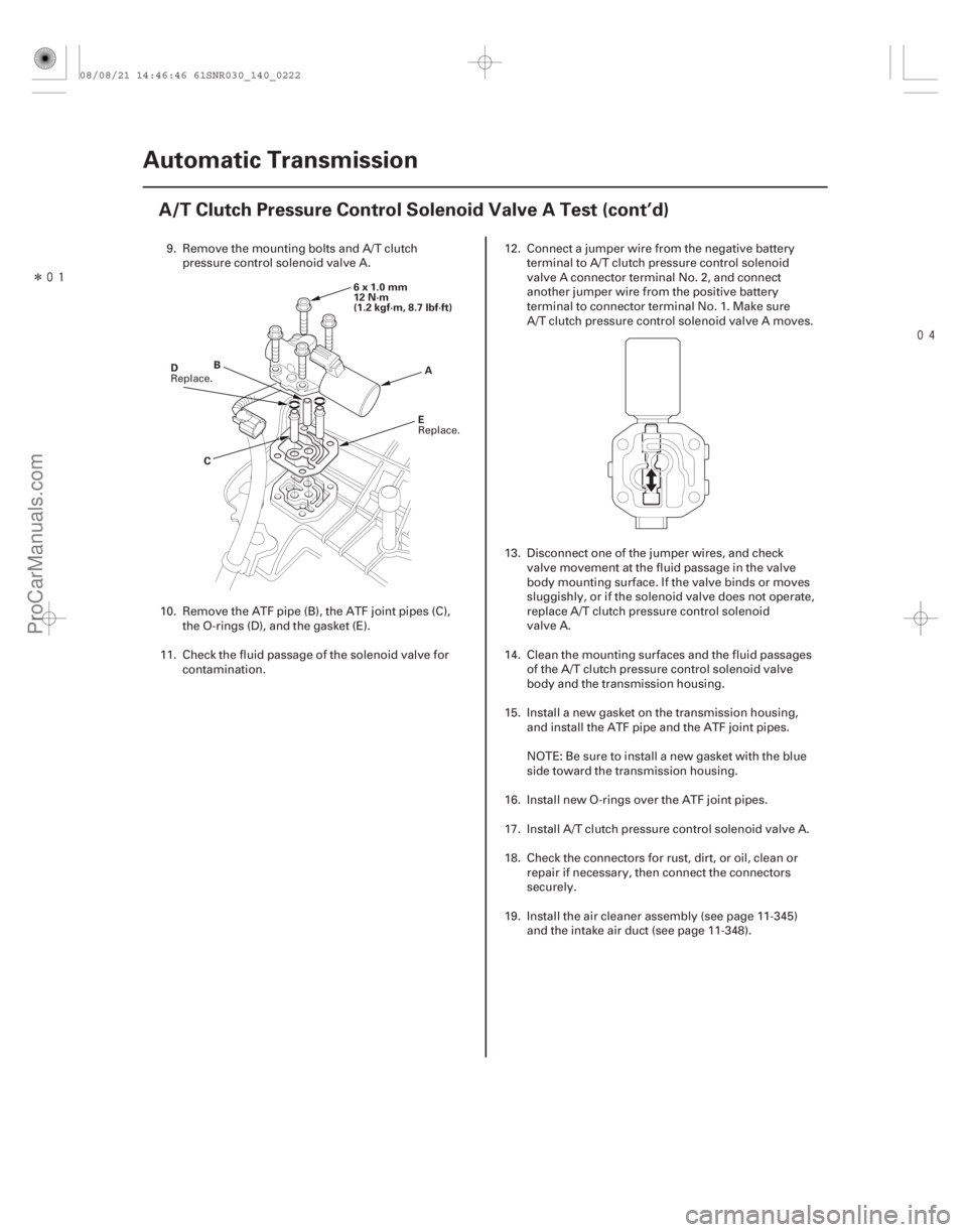
9. Remove the mounting bolts and A/T clutch
pressure control solenoid valve A.
10. Remove the ATF pipe (B), the ATF joint pipes (C), the O-rings (D), and the gasket (E).
11. Check the fluid passage of the solenoid valve for contamination. 12. Connect a jumper wire from the negative battery
terminal to A/T clutch pressure control solenoid
valve A connector terminal No. 2, and connect
another jumper wire from the positive battery
terminal to connector terminal No. 1. Make sure
A/T clutch pressure control solenoid valve A moves.
13. Disconnect one of the jumper wires, and check valve movement at the fluid passage in the valve
body mounting surface. If the valve binds or moves
sluggishly, or if the solenoid valve does not operate,
replace A/T clutch pressure control solenoid
valve A.
14. Clean the mounting surfaces and the fluid passages of the A/T clutch pressure control solenoid valve
body and the transmission housing.
15. Install a new gasket on the transmission housing, and install the ATF pipe and the ATF joint pipes.
NOTE: Be sure to install a new gasket with the blue
side toward the transmission housing.
16. Install new O-rings over the ATF joint pipes.
17. Install A/T clutch pressure control solenoid valve A.
18. Check the connectors for rust, dirt, or oil, clean or repair if necessary, then connect the connectors
securely.
19. Install the air cleaner assembly (see page 11-345) and the intake air duct (see page 11-348).
Replace.
Replace.
08/08/21 14:46:46 61SNR030_140_0222
ProCarManuals.com
DYNOMITE -2009-
Page 1137 of 2893

����
�(�#�'�������
���
�����
�����
��������� �����)����
14-221
A/T Clutch Pressure Control Solenoid Valve A Replacement
A
C B
6x1.0mm
12 N·m
(1.2 kgf·m, 8.7 lbf·ft)
E
D
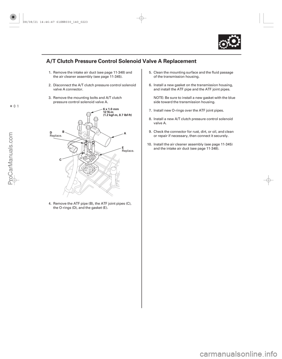
1. Remove the intake air duct (see page 11-348) and
the air cleaner assembly (see page 11-345).
2. Disconnect the A/T clutch pressure control solenoid valve A connector.
3. Remove the mounting bolts and A/T clutch pressure control solenoid valve A.
4. Remove the ATF pipe (B), the ATF joint pipes (C), the O-rings (D), and the gasket (E). 5. Clean the mounting surface and the fluid passage
of the transmission housing.
6. Install a new gasket on the transmission housing, and install the ATF pipe and the ATF joint pipes.
NOTE: Be sure to install a new gasket with the blue
side toward the transmission housing.
7. Install new O-rings over the ATF joint pipes.
8. Install a new A/T clutch pressure control solenoid valve A.
9. Check the connector for rust, dirt, or oil, and clean or repair if necessary, then connect it securely.
10. Install the air cleaner assembly (see page 11-345) and the intake air duct (see page 11-348).
Replace.
Replace.
08/08/21 14:46:47 61SNR030_140_0223
ProCarManuals.com
DYNOMITE -2009-
Page 1139 of 2893

���������
14-223
AD
BC
A
6x1.0mm
12 N·m (1.2 kgf·m, 8.7 lbf·ft) F
E
B
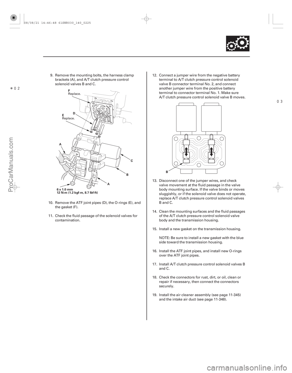
9. Remove the mounting bolts, the harness clampbrackets (A), and A/T clutch pressure control
solenoid valves B and C.
10. Remove the ATF joint pipes (D), the O-rings (E), and the gasket (F).
11. Check the fluid passage of the solenoid valves for contamination. 12. Connect a jumper wire from the negative battery
terminal to A/T clutch pressure control solenoid
valve B connector terminal No. 2, and connect
another jumper wire from the positive battery
terminal to connector terminal No. 1. Make sure
A/T clutch pressure control solenoid valve B moves.
13. Disconnect one of the jumper wires, and check valve movement at the fluid passage in the valve
body mounting surface. If the valve binds or moves
sluggishly, or if the solenoid valve does not operate,
replace A/T clutch pressure control solenoid valves
BandC.
14. Clean the mounting surfaces and the fluid passages of the A/T clutch pressure control solenoid valve
body and the transmission housing.
15. Install a new gasket on the transmission housing.
NOTE: Be sure to install a new gasket with the blue
side toward the transmission housing.
16. Install the ATF joint pipes, and install new O-rings over the ATF joint pipes.
17. Install A/T clutch pressure control solenoid valves B and C.
18. Check the connectors for rust, dirt, or oil, clean or repair if necessary, then connect the connectors
securely.
19. Install the air cleaner assembly (see page 11-345) and the intake air duct (see page 11-348).
Replace.
Replace.
08/08/21 14:46:48 61SNR030_140_0225
ProCarManuals.com
DYNOMITE -2009-