Page 781 of 2893
�
�
�
���
��
����
13-10Manual Transmission
Transmission Removal (cont’d)
A
B
B
B
A
B A
B
C
DB
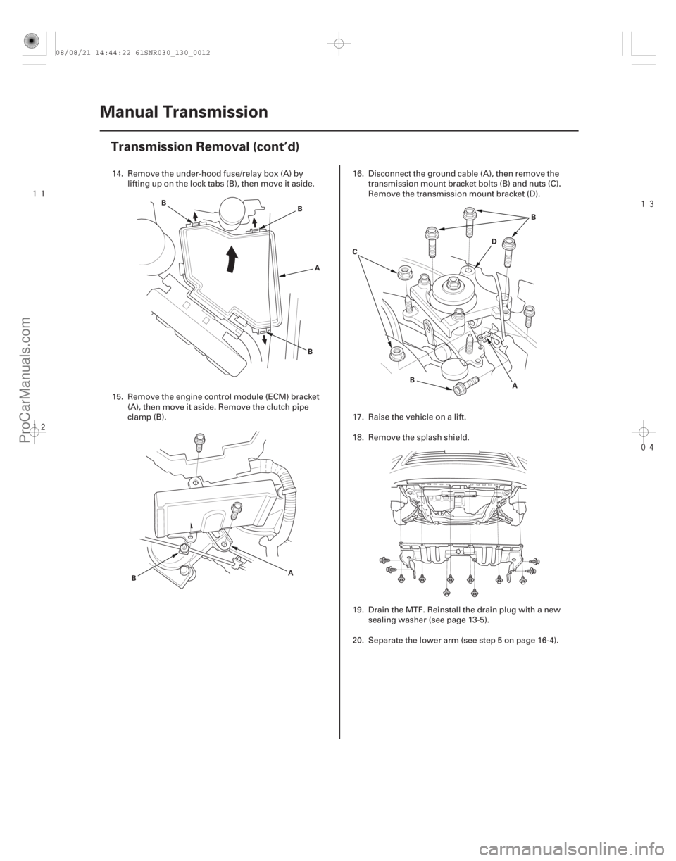
14. Remove the under-hood fuse/relay box (A) by
lifting up on the lock tabs (B), then move it aside.
15. Remove the engine control module (ECM) bracket (A), then move it aside. Remove the clutch pipe
clamp (B). 16. Disconnect the ground cable (A), then remove the
transmission mount bracket bolts (B) and nuts (C).
Remove the transmission mount bracket (D).
17. Raise the vehicle on a lift.
18. Remove the splash shield.
19. Drain the MTF. Reinstall the drain plug with a new sealing washer (see page 13-5).
20. Separate the lower arm (see step 5 on page 16-4).
08/08/21 14:44:22 61SNR030_130_0012
ProCarManuals.com
DYNOMITE -2009-
Page 791 of 2893
����
����� �����
’06 model ’07-09 models
13-20Manual Transmission
Transmission Installation (cont’d)
A
B
C
A
D 8x1.25mm
27 N·m
(2.8 kgf·m,
20 lbf·ft)
BC
C
B
A
(P/N 08C30-B0234M) 8x1.25mm
27 N·m
(2.8 kgf·m,
20 lbf·ft)
BC
C
A (P/N 08C30-B0234M) E
36. Install the harness clips (A) on the shift cable
bracket (B) and the harness bracket (C).
37. Apply a light coat of silicone grease (P/N 08C30- B0234M) to the shift cable ends (A).
NOTE: Make sure not to get any silicone grease on
the terminal part of the connectors and switches,
especially if you have silicone grease on your
hands or gloves. 38. Install the shift cable bracket (B) and the shift cables
(C), then install new cotter pins (D) or lock pins (E).
Replace.
08/08/21 14:44:54 61SNR030_130_0022
ProCarManuals.com
DYNOMITE -2009-
Page 795 of 2893
����
�(�#�'���������������
�����
�����������!�����)����
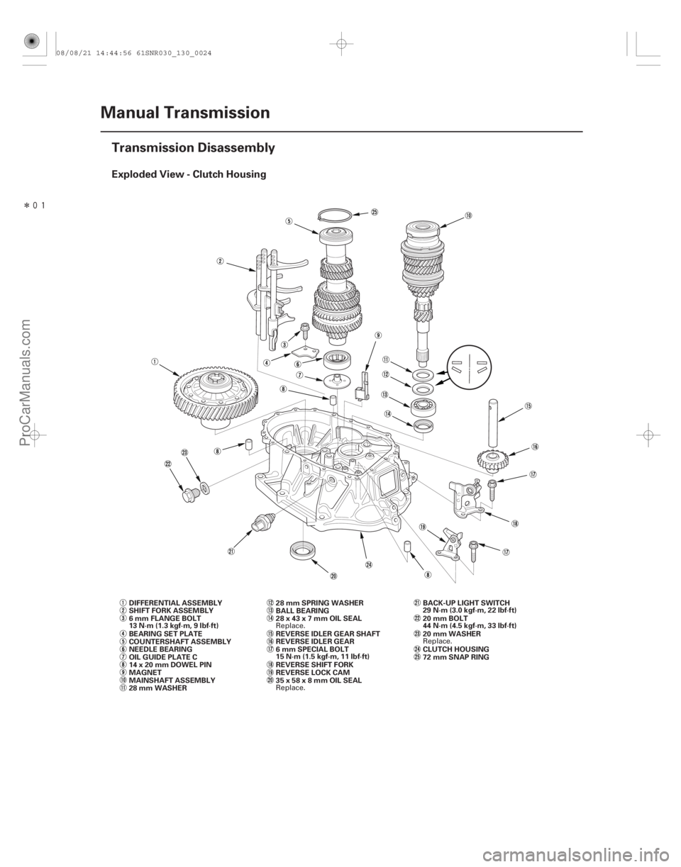
Exploded View - Clutch Housing
13-22Manual Transmission
Transmission Disassembly
MAINSHAFT ASSEMBLY COUNTERSHAFT ASSEMBLY
REVERSE IDLER GEAR
REVERSE LOCK CAM BALL BEARING
REVERSE IDLER GEAR SHAFT
14x20mmDOWELPIN
MAGNET DIFFERENTIAL ASSEMBLY
OIL GUIDE PLATE C BEARING SET PLATE
NEEDLE BEARING
28 mm WASHER 28 mm SPRING WASHER
REVERSE SHIFT FORK
SHIFT FORK ASSEMBLY
CLUTCH HOUSING
72 mm SNAP RING
6 mm FLANGE BOLT
13 N·m (1.3 kgf·m, 9 lbf·ft)
35x58x8mmOILSEAL 28x43x7mmOILSEAL20 mm WASHER BACK-UP LIGHT SWITCH
29 N·m (3.0 kgf·m, 22 lbf·ft)
20 mm BOLT
44 N·m (4.5 kgf·m, 33 lbf·ft)
6mmSPECIALBOLT
15 N·m (1.5 kgf·m, 11 lbf·ft)
Replace. Replace. Replace.
08/08/21 14:44:56 61SNR030_130_0024
ProCarManuals.com
DYNOMITE -2009-
Page 796 of 2893

10 mm SEALING WASHER
FILLER PLUG
44 N·m (4.5 kgf·m, 33 lbf·ft)
40x56x8mmOIL")
�����
Exploded View - Transmission Housing
13-23
TRANSMISSION HOUSING32 mm SEALING CAP
34 N·m (3.5 kgf·m, 25 lbf·ft)
10 mm SEALING WASHER
FILLER PLUG
44 N·m (4.5 kgf·m, 33 lbf·ft)
40x56x8mmOILSEAL
10 mm FLANGE BOLT
44 N·m (4.5 kgf·m, 33 lbf·ft)
14 mm SEALING WASHER
TRANSMISSION HANGER A 8 mm FLANGE BOLT
27 N·m (2.8 kgf·m, 20 lbf·ft)
INTERLOCK BOLT
39 N·m (4.0 kgf·m, 29 lbf·ft)
OIL GUIDE PLATE M
72 mm SHIM
OIL GUTTER PLATE
DRAIN PLUG
39 N·m (4.0 kgf·m, 29 lbf·ft) 20 mm SEALING WASHER STEEL BALL SPRING
TRANSMISSION HANGER B DETENT BOLT
22 N·m (2.2 kgf·m, 16 lbf·ft)
12 mm SEALING WASHER
HARNESS BRACKET A
6 x 30 mm FLANGE BOLT
12 N·m (1.2 kgf·m, 9 lbf·ft) 8x14mmDOWELPIN
CHANGE LEVER ASSEMBLY TRANSMISSION HANGER
10 mm FLANGE BOLT
44 N·m (4.5 kgf·m, 33 lbf·ft)
PLAIN WASHER
6 x 20 mm FLANGE BOLT
12 N·m (1.2 kgf·m, 9 lbf·ft) 6 mm FLANGE BOLT
12 N·m (1.2 kgf·m, 9 lbf·ft) OUTPUT SHAFT (COUNTERSHAFT)
SPEED SENSOR
O-RING
80 mm SHIM
(cont’d)
Replace.
Replace.
Replace. Replace. Replace. Replace.
08/08/21 14:44:57 61SNR030_130_0025
ProCarManuals.com
DYNOMITE -2009-
Page 797 of 2893
��������� ����
�����
13-24 Manual Transmission
Transmission Disassembly (cont’d)
C
A
A
D E
B C
F
D
B
AB B
C
D
A
D
AB
D
C D
D
E
G
F
NOTE: Place the clutch housing on two pieces of wood
thick enough to keep the mainshaft from hitting the
workbench.
1. Remove the release fork and the replace bearing (see page 12-24).
2. Remove the detent bolts (A), the 12 mm sealing washers (B), the springs (C), the steel balls (D), and
the back-up light switch (E). Then remove the
transmission hanger (F).
3. Remove the 20 mm bolt (A) and the 20 mm sealing washer (B). 4. Remove the interlock bolt (B), the change lever
assembly(C),the8x14mmdowelpins(D),and
harness bracket A.
5. Remove the drain plug (A), the filler plug (B), the 10 mm flange bolt (C), and the sealing washers (D).
6. Remove the output shaft (countershaft) speed sensor (E) with the O-ring (F) and the plain washer
(G).
08/08/21 14:44:58 61SNR030_130_0026
ProCarManuals.com
DYNOMITE -2009-
Page 798 of 2893
��������� �����
�
��
13-25
A
B
A
B
C
D D
D A
A B
7. Loosen the 8 mm flange bolts in a crisscross
pattern in several steps, then remove them with
transmission hanger A and transmission hanger B.
8. Remove the 32 mm sealing cap (A).
9. While expanding the 72 mm snap ring (B) on the countershaft ball bearing with snap ring pliers, lift
the transmission housing (C). Release the snap ring
pliers, and remove the transmission housing and
the three 14 x 20 mm dowel pins (D). 10. Remove the reverse lock cam (A).
11. Remove the reverse idler gear (A) and the reverse
idler gear shaft (B).
(cont’d)
08/08/21 14:44:59 61SNR030_130_0027
ProCarManuals.com
DYNOMITE -2009-
Page 801 of 2893
���
�(�#�'���������������
���������������
�"�����)����
13-28Manual Transmission
Change Lever Assembly Disassembly/Reassembly
BREATHER CAP
6x1.0mm
12 N·m
(1.2 kgf·m, 9 lbf·ft)
ROLLER
WASHER
5TH SELECT
SPRING
SELECT STOP
PLATE SHIFT ARM
COVER
INTERLOCK REVERSE LOCK CAM
STRIKER8 mm SPRING WASHER
8mmSPECIALBOLT
31 N·m
(3.2 kgf·m, 23 lbf·ft)
DUST COVER CHANGE LEVER
CHANGE LEVER COVER
SELECT LEVER
DUST SEAL
1ST/2ND SELECT
SPRING SHIFT ARM
OIL SEAL
(P/N 08798-9002)
(P/N 08798-9002)
(P/N 08798-9002)
NOTE: Prior to reassembling, clean all the parts in solvent, dry them, and apply grease to the contact surfaces as
shown.
Turn toward the front of
the vehicle, then install it. Be careful not to damage the
dust seal when installing it.
Replace.
Replace.
08/08/21 14:45:01 61SNR030_130_0030
ProCarManuals.com
DYNOMITE -2009-
Page 808 of 2893
���� �µ�µ
�µ�µ
�µ�µ
�µ�µ
�µ�µ
Standard:
A Ball Bearing Contact Area (transmission housing
side):27.987 28.000 mm (1.1018 1.1024 in.)
B")
�����
��
�(�#�'���������������
�����������������"�����)���� �µ�µ
�µ�µ
�µ�µ
�µ�µ
�µ�µ
Standard:
A Ball Bearing Contact Area (transmission housing
side):27.987 28.000 mm (1.1018 1.1024 in.)
B 4th/5th Gear Distance Collar Contact Area: 31.984 32.000 mm (1.2592 1.2598 in.)
C Needle Bearing Contact Area: 38.984 39.000 mm (1.5348 1.5354 in.)
D Ball Bearing Contact Area (clutch housing side): 27.977 27.990 mm (1.1015 1.1020 in.)
E Bushing Contact Area: 20.80 20.85 mm (0.819 0.821 in.)
Service Limit:
A: 27.93 mm (1.100 in.)
B: 31.93 mm (1.257 in.)
C: 38.93 mm (1.533 in.)
D: 27.92 mm (1.099 in.)
E: 20.75 mm (0.817 in.)
13-3413-34 Manual Transmission
Mainshaft Disassembly (cont’d) Mainshaft Inspection
A
B
ED
CB
A
3. Support 3rd gear (A) on steel blocks, and press themainshaft out of the 3rd/4th synchro hub (B) and
3rd gear.
NOTE: Do not use a jaw-type puller; it can damage
the gear teeth. 1. Inspect the gear and bearing contact areas for wear
and damage, then measure the mainshaft at points
A, B, C, D, and E. If any part of the mainshaft is less
than the service limit, replace it.
08/08/21 14:45:04 61SNR030_130_0036
ProCarManuals.com
DYNOMITE -2009-