Page 1664 of 2893

1. Install the VSA modulator-control unit onto the bracket.
2. Install the bracket with the VSA")
Installation
19-172VSA System Components
VSA Modulator-Control Unit Removal and Installation (cont’d)
1. Install the VSA modulator-control unit onto the bracket.
2. Install the bracket with the VSA modulator-control unit to the body.
3. Reconnect the six brake lines, then tighten the flare nuts to the specified torque.
4. Align the connecting surface of the VSA modulator-control unit 37P connector to the VSA modulator-control unit.
5. Pull up the lever of the VSA m
odulator-control unit 37P connector, then confirm the connector is fully seated.
6. Bleed the brake system (see page 19-9).
7. Do the VSA sensor neutral position memorization (see page 19-169).
8. Start the engine, and make sure the ABS and the VSA indicators go off.
9. Test-drive the vehicle, and make sure the ABS, and the VSA indicators do not come on. NOTE: If the brake pedal is spongy, there may be air trapped in the modulator which could then be induced into
the normal brake system during modulation. Bleed the brake system again (see page 19-9).
08/08/21 15:06:47 61SNR030_190_0172
ProCarManuals.com
DYNOMITE -2009-
Page 1667 of 2893
 and the sensor hole in the knuckle
(B).
5. Insert the guide pin to")
�����
����������
19-175
A
B
A
07AAG-SVBA100 B
07AAG-SVBA100
A
4. Apply multi-purpose grease to the wheel speedsensor O-ring (A) and the sensor hole in the knuckle
(B).
5. Insert the guide pin tool (A) into the wheel speed sensor bolt hole until the shoulder of the tool
contacts the wheel speed sensor bracket.
NOTE: To prevent O-ring damage, the wheel speed
sensor must be installed with the guide pin tool. 6. Insert the wheel speed sensor (A) and the guide pin
tool (B) into the bolt hole on the knuckle.
NOTE: To ensure proper alignment when pushing
the wheel speed sensor into the knuckle housing,
do not hold the sensor bracket during installation,
hold the sensor wire.
7. Gently push and pull the wheel speed sensor in and out to make sure the O-ring is sliding properly in its
housing. While you are doing this, make sure the
sensor doesn’t come out of the knuckle assembly. If
the sliding effort is too high, remove the wheel
speed sensor, inspect the O-ring for damage, and
start the installation process again.
8. Remove the guide pin tool, then install the bolt, and tighten it to specified torque.
9. Clean the mating surfaces between the brake disc and the inside of the wheel, then install the front
wheel.
10. Start the engine, and make sure the ABS and the VSA indicators go off.
11. Test-drive the vehicle, and make sure the ABS and the VSA indicators do not come on.
08/08/21 15:06:48 61SNR030_190_0175
ProCarManuals.com
DYNOMITE -2009-
Page 1754 of 2893
�
��
S
pecial Tools Required
20-78 Interior Trim
Trim Removal/Installation - Rear Shelf Area
A F
astener Locations
: Clip
A
(White)
’06 mo")
��������
�(�#�'��������������������������������� �����)�
��
S
pecial Tools Required
20-78 Interior Trim
Trim Removal/Installation - Rear Shelf Area
A F
astener Locations
: Clip
A
(White)
’06 model, 6
’07-09 models, 7
’06 model
’07-09 models A
A
A
A AAA
A
A
A
AA
A
KTC trim tool set SOJATP2014
SRS components are located in this area. Review the
S
RS component locations (see page 24-11) and the
precautions and procedures (see page 24-13) before
doing repairs or service.
NOTE: Put on gloves to protect your hands.
Take care not to bend or scratch the rear shelf or the trim.
Use the appropriate tool from the KTC trim tool set to avoid damage when removing components.
1. Remove these items: Rear seat cushion (see page 20-133)
Rear seat-back (see page 20-131)
Rear door opening seal, as needed (see step 3 onpage 20-68)
C-pillar trim, both sides (see step 3 on page 20-75)
2. From the trunk compartment, disconnect the high mount brake light connector (A). 3.
From the trunk compartment, release the six or
seven white clips (A) by tapping on them.
08/08/21 15:01:36 61SNR030_200_0080
ProCarManuals.com
DYNOMITE -2009-
Page 1755 of 2893

A
B
C D
FG
E
B
D G
A
D
E G
4. Release the hook (A) by pushing in on the detents
(B) on the rear shelf (C), then lift up on the front
edge")
��������
20-79
AB
C
A
B
C Fastener Locations
: Clip, 4(White)
A
B
C D
FG
E
B
D G
A
D
E G
4. Release the hook (A) by pushing in on the detents
(B) on the rear shelf (C), then lift up on the front
edge of the shelf at each detent. 5. Lift the rear shelf (A) upward to detach the
remaining four clips, and release the hooks (B) of
the high mount brake light from the rear shelf.
Release the pin (C) from the holes on the body.
6. Release each anchor rod (D) out through the hole in the rear shelf, and pull both rear seat belts (E) and
rear center seat belt (F) out through the slits (G) in
the rear shelf.
7. Install the shelf in the reverse order of removal, and note these items:
If the clips are damaged or stress-whitened, replace them with new ones.
When installing the rear shelf, slip the rear seat belt through the slit and the rear center seat belt
into the lid opening in the rear shelf.
Push the clips and the hooks into place securely.
Make sure the high mount brake light connector is connected securely.
08/08/21 15:01:36 61SNR030_200_0081
ProCarManuals.com
DYNOMITE -2009-
Page 1761 of 2893

Fastener Locations
:Bolt,2
C
E
F
G A
B
C
A
Fastener Locations :Bolt,4
8x1.25mm
22 N·m
(2.2 kgf·m,
16 lbf·ft) A
6. Push th")
����
��������
����
20-85
A
B
B
A
B D
B
5x0.8mm
5N·m
(0.5 kgf·m,
4lbf·ft)
Fastener Locations
:Bolt,2
C
E
F
G A
B
C
A
Fastener Locations :Bolt,4
8x1.25mm
22 N·m
(2.2 kgf·m,
16 lbf·ft) A
6. Push the hook (A) with a flat-tip screwdriver
wrapped with protective tape, and turn the holder
(B) 90 °, then pull it out.
7. Remove the individual map light assembly (A). –1 Remove the lenses (B).
–2 Remove the bolts.
–3 If equipped, release the four tabs (C), then pullout the moonroof switch (D) or the navigation
microphone.
–4 Disconnect the front individual map light connector (E). If equipped, disconnect the
moonroof switch connector (F) and the
navigation microphone connector (G). 8. Without moonroof: Remove the driver’s dashboard
undercover (see page 20-104).
9. Detach the harness clips (A) from the A-pillar (B), and disconnect the roof wire harness connector (C).
10. Remove the center console (see page 20-92).
11. Slide both front seats all the way back, and recline the seat-backs fully.
12. Remove the bolts securing the parking brake base frame (A), and lay it down as needed.
(cont’d)
08/08/21 15:01:40 61SNR030_200_0087
ProCarManuals.com
DYNOMITE -2009-
Page 1767 of 2893
����
��������
����
20-90Interior Trim
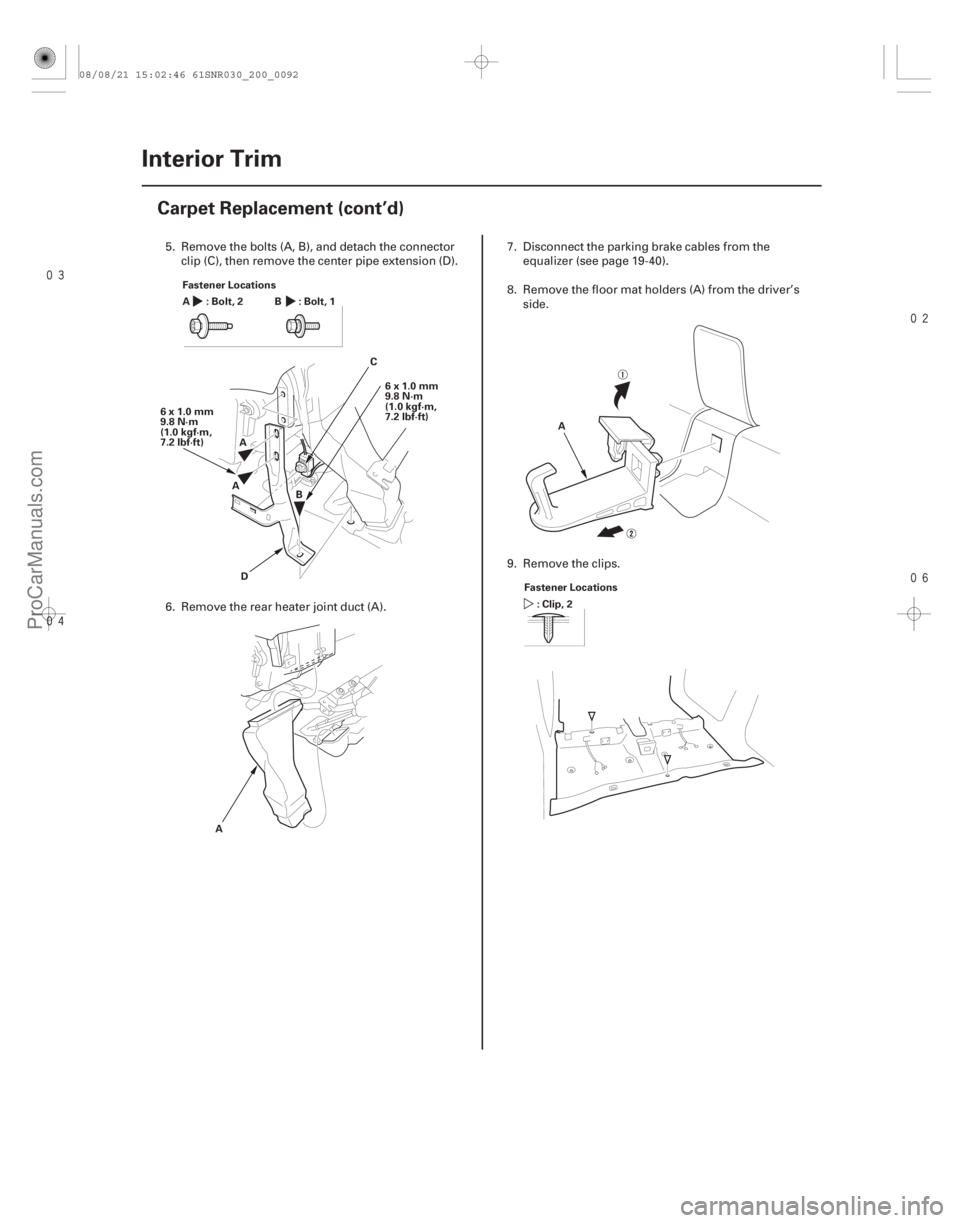
Carpet Replacement (cont’d)
Fastener Locations
:Bolt,2
A:Bolt,1
C
D
6x1.0mm
9.8 N·m
(1.0 kgf·m,
7.2 lbf·ft)
6x1.0mm
9.8 N·m
(1.0 kgf·m,
7.2 lbf·ft)
A A
B
B
A A
Fastener Locations :Clip,2
5. Remove the bolts (A, B), and detach the connector clip (C), then remove the center pipe extension (D).
6. Remove the rear heater joint duct (A). 7. Disconnect the parking brake cables from the
equalizer (see page 19-40).
8. Remove the floor mat holders (A) from the driver’s side.
9. Remove the clips.
08/08/21 15:02:46 61SNR030_200_0092
ProCarManuals.com
DYNOMITE -2009-
Page 1768 of 2893
����
20-91
AB
C
C
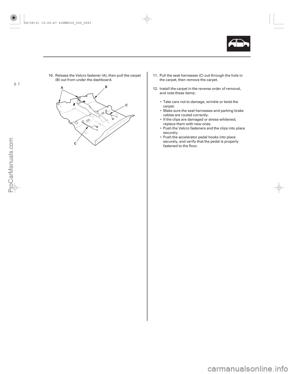
10. Release the Velcro fastener (A), then pull the carpet (B) out from under the dashboard. 11. Pull the seat harnesses (C) out through the hole in
the carpet, then remove the carpet.
12. Install the carpet in the reverse order of removal, and note these items:
Take care not to damage, wrinkle or twist the carpet.
Make sure the seat harnesses and parking brake cables are routed correctly.
If the clips are damaged or stress-whitened, replace them with new ones.
Push the Velcro fasteners and the clips into place securely.
Push the accelerator pedal hooks into place securely, and verify that the pedal is properly
fastened to the floor.
08/08/21 15:02:47 61SNR030_200_0093
ProCarManuals.com
DYNOMITE -2009-
Page 1771 of 2893
����
��������
20-94Consoles
Center Console Removal/Installation (cont’d)
A
B
C
B
A
B A
BC
8. Slide both front seats all the way back, and recline
the seat-back fully.
9. Slide the center console (A) rearward to release the pins (B) from the bracket (C).
10. Lift up the rear of the console (A), and remove it from the dashboard.
11. If equipped, disconnect the seat heater switch connectors (B). 12. Install the console in the reverse order of removal,
and note these items:
Make sure each connector is plugged in properly.
If the clips are damaged or stress-whitened, replace them with new ones.
Push the clips and the hooks into place securely.
When installing the center console panel, install the tabs (A) into the notch (B) of the parking brake
base frame (C).
08/08/21 15:02:48 61SNR030_200_0096
ProCarManuals.com
DYNOMITE -2009-