Page 2131 of 2893
���
����
�(�#����������������
�
�����
���������������)����
TYPE S model
22-18122-181
Brake Pedal Position Switch Test
A B
A
B
1. Remove the two s")
���
�(�#�'���������������
�
�������
�����
� �����)���
����
�(�#�'���������������
�
�����
���������������)����
TYPE S model
22-18122-181
Brake Pedal Position Switch Test
A B
A
B
1. Remove the two screws from the high mount brakelight (A).
2. Disconnect the terminals (B) and remove the high mount brake light.
3. Install the high mount brake light in the r everse
order of removal. 1. Disconnect the 4P connector (A) from the brake
pedal position switch (B).
2. Check for continuity between terminals No. 1 and No. 2.
There should be continuity when the brake pedal is pressed.
There should be no continuity when the brake pedal is released.
3. Check for continuity between terminals No. 3 and No. 4 (with cruise control).
There should be no continuity when the brake pedal is pressed.
There should be continuity when the brake pedal is released.
4. If necessary, adjust or replace the switch, or adjust the pedal height (see page 19-6).
08/08/21 14:27:41 61SNR030_220_0183
ProCarManuals.com
DYNOMITE -2009-
Page 2188 of 2893
����
������(�#�'���������������
�����������������������)����
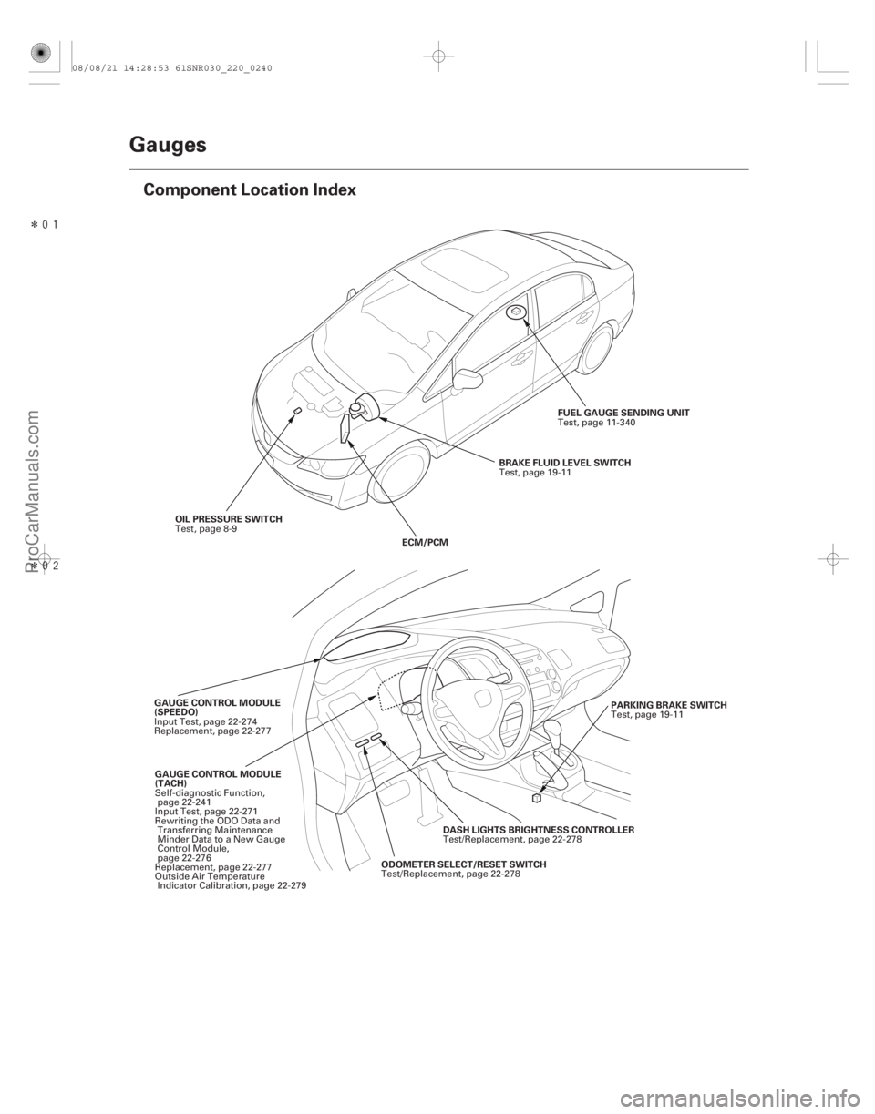
22-238Gauges
Component Location Index
OIL PRESSURE SWITCH
ECM/PCMBRAKE FLUID LEVEL SWITCH
FUEL GAUGE SENDING UNIT
GAUGE CONTROL MODULE
(TACH) ODOMETER SELECT/RESET SWITCHDASH LIGHTS BRIGHTNESS CONTROLLER
GAUGE CONTROL MODULE
(SPEEDO)
PARKING BRAKE SWITCH
Test, page 8-9
Test, page 19-11
Test, page 11-340
Self-diagnostic Function, page 22-241
Input Test, page 22-271
Rewriting the ODO Data and Transferring Maintenance
Minder Data to a New Gauge
Control Module,
page 22-276
Replacement, page 22-277
Outside Air Temperature Indicator Calibration, page 22-279 Test/Replacement, page 22-278Test/Replacement, page 22-278
Input Test, page 22-274
Replacement, page 22-277
Test, page 19-11
08/08/21 14:28:53 61SNR030_220_0240
ProCarManuals.com
DYNOMITE -2009-
Page 2192 of 2893

OFF")
�´�µ
���
The Indicator Drive Circuit Check
Switch Input Check
The Beeper Drive Circuit Check
The LCD Segment Check
The Gauge Drive Circuit Check
22-242Gauges
Self-diagnostic Function (cont’d)
OFF ON
OFF ON
OFF ON
OFF ON
Gauge needles
Beeper
5sec.
Self-diagnostic
mode
SEL/RESET
SWITCH
When entering the self-diagnostic mode, the following indicators blink:
A/T gear position indicator, ABS indicator, brake system indicator, charging system indicator, cruise control indicator,
cruise main indicator, door indicator, DRL indicator, EPS indicator, fog light indicator , high beam indicator,
immobilizer indicator, lights-on indicator, low fuel indicator, low oil pressure indicator, low tire pressure indicator ,
maintenance minder indicator, malfunction indicator lamp (MIL), REV limit indicator (TYPE S model), seat belt
reminder indicator, security indicator, side airbag cutoff indicator, SRS indicator, TPMS indicator , trunk indicator,
VSA activation indicator , VSA indicator , and washer fluid level indicator.
1: ’07 TYPE S and ’08-09 models
2: ’08-09 models
3: TYPE S and ’08 Premium and ’09 models
At the initial stage of the self-diagnostic function, the beep sounds intermittently, the beeper sounds continuously
when any of the following switch inputs are switched from OFF to ON:
Cruise control main, dash lights brightness controller volume ( ), ( ) button, mph km/h switch, parking brake switch,
SEL/RESET switch, SET, RESUME, CANCEL switches, and VSA OFF switch . : ’07 TYPE S and ’08-09 models
When entering the self-diagnostic mode, the beeper sounds five times.
When entering the self-diagnostic mode, all the segments blink five times.
When entering the self-diagnostic mode, the tachometer needle sweeps from the minimum position to maximum
position, then returns to the minimum position.
NOTE:
After the beeper stops sounding and the gauge needle returns to the minimum position, pushing the SEL/RESET
switch starts the Beeper Drive Circuit Check (one beep) and the Gauge Drive Circuit Check again.
The check cannot be started again until the gauge needle returns to the minimum position.
If the needle fails to sweep, or the beeper does not sound, replace the gauge control module (tach).
3 2
2
11
The needle sweeps from the
minimum position to the
maximum position, then return
to the minimum position.
08/08/21 14:35:12 61SNR030_220_0244
ProCarManuals.com
DYNOMITE -2009-
Page 2194 of 2893
����
Except TYPE S model
22-244Gauges
Circuit Diagram - Gauge Control Module (Tach)
UART
WHT
IG1 HOT in ON (II) and START (III)
UNDER-HOOD FUSE/REL")
������(�#�'���������������
�����������������������)����
Except TYPE S model
22-244Gauges
Circuit Diagram - Gauge Control Module (Tach)
UART
WHT
IG1 HOT in ON (II) and START (III)
UNDER-HOOD FUSE/RELAY BOX
5V
MAIN CIRCUIT
MAIN CIRCUIT
MICU
LT GRN
20
21
PNK
124
CAN L
CAN H
CHIME
BRN
WHT BRN
RED 19
1
WHT No. 2 (IG) (50 A)
GAUGE CONTROL MODULE (TACH) 18 17 TACHOMETER ORN
IG1
BAT
BLU
WHT
No. 23 (10 A)
BATTERY
IGNITION SWITCH
No. 1 (BAT) (100 A)
(7.5 A) No. 10UNDER-DASH
FUSE/RELAY
BOX
GAUGE CONTROL
MODULE (SPEEDO)
DRIVE
CIRCUIT DIMMING
CIRCUIT
PARKING
BRAKE
REMINDER
SEAT
BELT
REMINDER
KEY-IN
REMINDER
F-CAN
TRANSCEIVER B-CAN
TRANSCEIVER
IMMOBILIZER-
KEYLESS
CONTROL UNIT GAUGE
CONTROL
MODULE
(SPEEDO) 10 V
STABILIZING
CIRCUIT
HIGH BEAM
INDICATOR
(LED)
LIGHTS-ON
REMINDER
CLIMATE CONTROL
UNIT
HANDSFREELINK
CONTROL UNIT*3 IMMOBILIZER
INDICATOR
(LED)
ON/OFF
5V
5V
CONTROL
CIRCUIT
H1
D4 G2D2
Q1 P5 P10 Q9
A
ECM/PCM
ABS MODULATOR-
CONTROL UNIT*1
VSA MODULATOR-
CONTROL UNIT*2
YAW RATE-LATERAL
ACCELERATION SENSOR*2
EPS CONTROL UNIT
TPMS CONTROL UNIT*2
DATA LINK CONNECTOR
SRS UNIT
MICU
08/08/21 14:35:12 61SNR030_220_0246
ProCarManuals.com
DYNOMITE -2009-
Page 2199 of 2893
�����
�µ
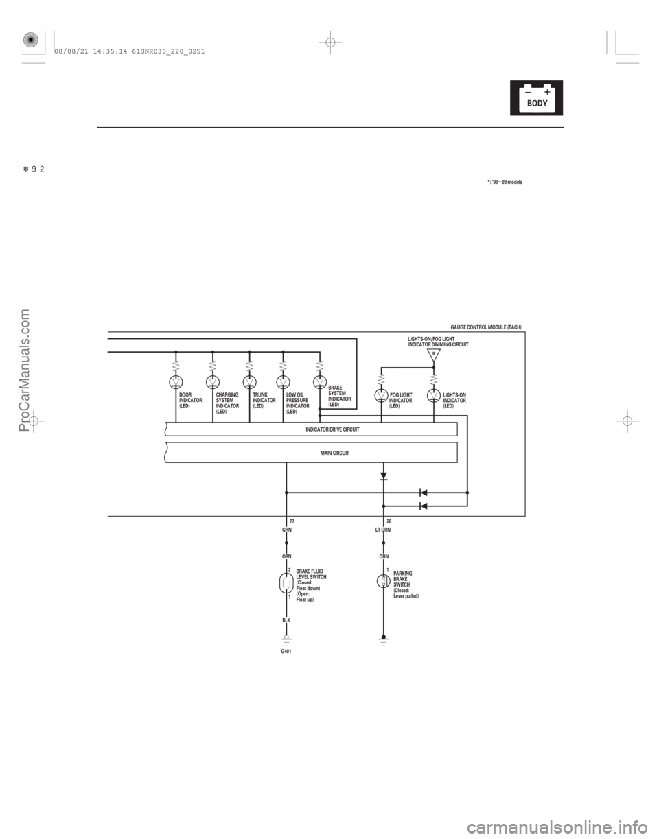
22-249
B
28
LT GRN
MAIN CIRCUIT
INDICATOR DRIVE CIRCUIT
TRUNK
INDICATOR
(LED)
LOW OIL
PRESSURE
INDICATOR
(LED)
PARKING
BRAKE
SWITCH
(Closed:
Lever pulled)LIGHTS-ON
INDICATOR
(LED)
LIGHTS-ON/FOG LIGHT
INDICATOR DIMMING CIRCUIT
DOOR
INDICATOR
(LED)
1FOG LIGHT
INDICATOR
(LED)
BRAKE
SYSTEM
INDICATOR
(LED) *: ’08 09 models
GRN BLK
G401 1 2
ORN 27
BRAKE FLUID
LEVEL SWITCH
(Closed:
Float down)
(Open:
Float up) ORN
CHARGING
SYSTEM
INDICATOR
(LED)
GAUGE CONTROL MODULE (TACH)
08/08/21 14:35:14 61SNR030_220_0251
ProCarManuals.com
DYNOMITE -2009-
Page 2200 of 2893
����
TYPE S model
22-250Gauges
Circuit Diagram - Gauge Control Module (Tach) (cont’d)
UART
WHT
IG1 HOT in ON (II) and START (III)
UNDER-HOOD FUSE")
������(�#�'���������������
�����������������������)����
TYPE S model
22-250Gauges
Circuit Diagram - Gauge Control Module (Tach) (cont’d)
UART
WHT
IG1 HOT in ON (II) and START (III)
UNDER-HOOD FUSE/RELAY BOX
ECM
VSA MODULATOR-
CONTROL UNIT
YAW RATE-LATERAL
ACCELERATION SENSOR
EPS CONTROL UNIT
TPMS CONTROL UNIT*1
DATA LINK CONNECTOR
SRS UNIT MAIN CIRCUIT
MAIN CIRCUIT
MICU
GRY
2
21
PNK
124
CAN L
CAN H
CHIME
BRN
WHT BRN
RED 19
1
WHT No. 2 (IG) (50 A)
GAUGE CONTROL MODULE (TACH) 18 17 TACHOMETER ORN
IG1
BAT
BLU
WHT
No. 23 (10 A)
BATTERY
IGNITION SWITCH
No. 1 (BAT) (100 A)
(7.5 A) No. 10UNDER-DASH
FUSE/RELAY
BOX
GAUGE CONTROL
MODULE (SPEEDO)
DRIVE
CIRCUIT DIMMING
CIRCUIT
PARKING
BRAKE
REMINDER
SEAT
BELT
REMINDER
KEY-IN
REMINDER
F-CAN
TRANSCEIVER B-CAN
TRANSCEIVER
IMMOBILIZER-
KEYLESS
CONTROL UNIT GAUGE
CONTROL
MODULE
(SPEEDO) 10 V
STABILIZING
CIRCUIT
HIGH BEAM
INDICATOR
(LED)
LIGHTS-ON
REMINDER
CLIMATE CONTROL
UNIT
HANDSFREELINK
CONTROL UNIT*2 IMMOBILIZER
INDICATOR
(LED)
H1
D4 G2D2
Q1 P5 P10 Q9
A DRIVER DRIVERMAIN CIRCUIT
MICU
08/08/21 14:35:15 61SNR030_220_0252
ProCarManuals.com
DYNOMITE -2009-
Page 2205 of 2893
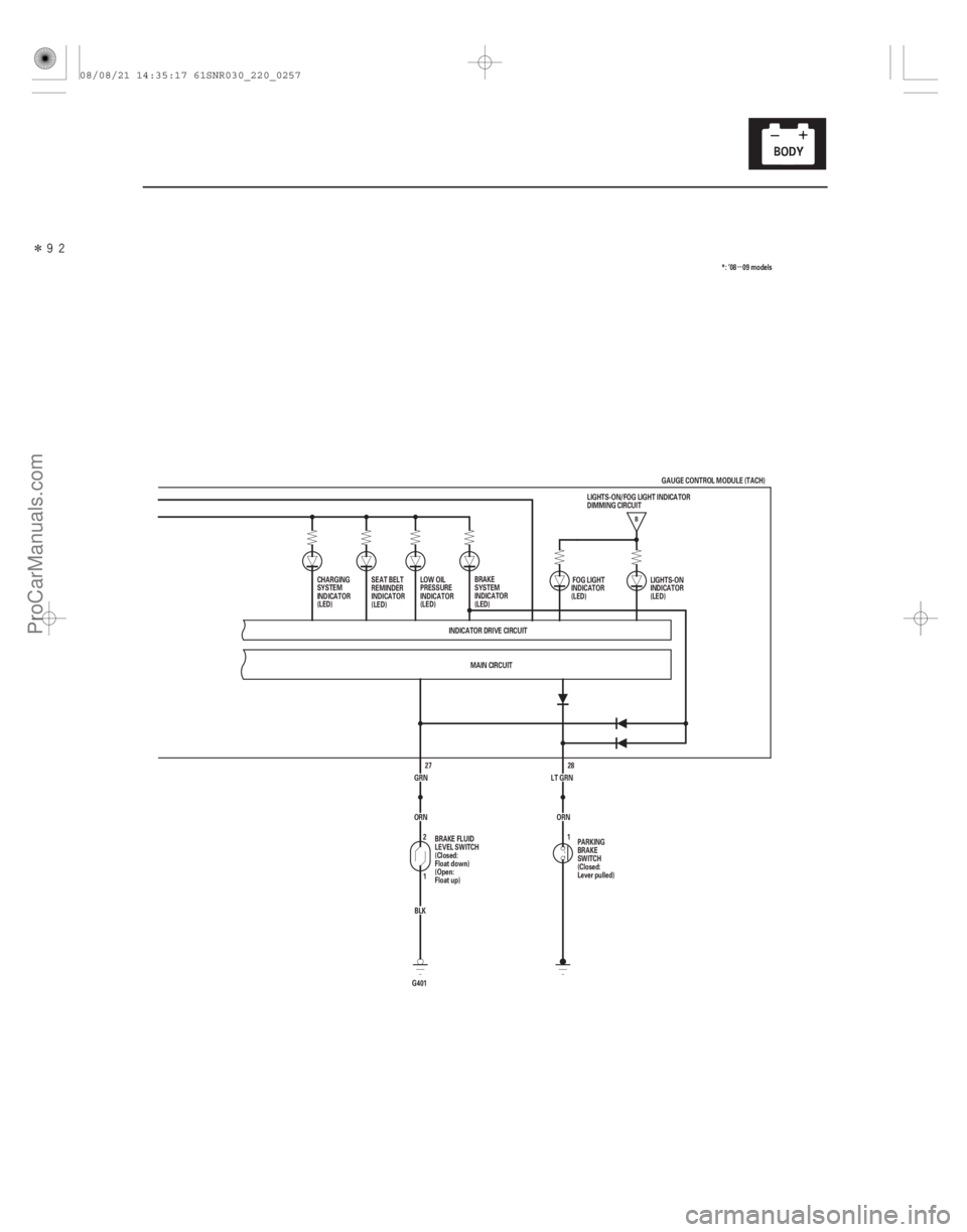
�����
�µ
22-255
B
28
LT GRN
MAIN CIRCUIT
INDICATOR DRIVE CIRCUIT
SEAT BELT
REMINDER
INDICATOR
(LED)
LOW OIL
PRESSURE
INDICATOR
(LED)
PARKING
BRAKE
SWITCH
(Closed:
Lever pulled)LIGHTS-ON
INDICATOR
(LED)
1 FOG LIGHT
INDICATOR
(LED)
BRAKE
SYSTEM
INDICATOR
(LED) *: ’08 09 models
GRN BLK
G401 1 2
ORN 27
BRAKE FLUID
LEVEL SWITCH
(Closed:
Float down)
(Open:
Float up) ORN
CHARGING
SYSTEM
INDICATOR
(LED)
GAUGE CONTROL MODULE (TACH)
LIGHTS-ON/FOG LIGHT INDICATOR
DIMMING CIRCUIT
08/08/21 14:35:17 61SNR030_220_0257
ProCarManuals.com
DYNOMITE -2009-
Page 2223 of 2893
,")
�´
�´
Cavity Wire Test condition Test: Desired result Possible cause if desired result
is not obtained
22-273
5 YEL Ignition switch ON
(II), ILLUMI ( )
button pressed Measure the voltage to ground:
There should be less than 1 V.
Poor ground (G501)
Faulty dash light brightness
controller and odometer
select/reset switch
An open in the wire
Ignition switch ON
(II), ILLUMI ( )
button released Measure the voltage to ground:
There should be more than 5 V.
Faulty dash light brightness
controller and odometer
select/reset switch
A short to ground in the wire
6 BLU Ignition switch ON (II), SELECT/RESET
button pressed Measure the voltage to ground:
There should be less than 1 V.
Poor ground (G501)
Faulty dash light brightness
controller and odometer
select/reset switch
An open in the wire
Ignition switch ON
(II), SELECT/RESET
button released Measure the voltage to ground:
There should be more than 5 V.
Faulty dash light brightness
controller and odometer
select/reset switch
A short to ground in the wire
7 PUR Ignition switch ON (II), km/h-mph
button pressed Measure the voltage to ground:
There should be less than 1 V.
Poor ground (G501)
Faulty dash light brightness
controller and odometer
select/reset switch
An open in the wire
Ignition switch ON
(II), km/h-mph
button released Measure the voltage to ground:
There should be more than 5 V.
Faulty dash light brightness
controller and odometer
select/reset switch
A short to ground in the wire
8 BLU Ignition switch ON (II), washer fluid is
half or more in the
washer reservoir Measure the voltage to ground:
There should be more than 5 V.
Faulty washer fluid level
switch
A short to ground in the wire
Ignition switch ON
(II), washer fluid is
empty in the
washer reservoir Measure the voltage to ground:
There should be less than 1 V.
Poor ground (G401)
Faulty washer fluid level
switch
An open in the wire
27 GRN Ignition switch ON (II), brake fluid is
full level in the
reservoir Measure the voltage to ground:
There should be less than 1 V.
Poor ground (G401)
Faulty brake fluid level switch
An open in the wire
Ignition switch ON
(II), brake fluid is
lower level in the
reservoir Measure the voltage to ground:
There should be more than 5 V.
Faulty brake fluid level switch
A short to ground in the wire
28 LT GRNIgnition switch ON
(II), parking brake
lever pulled Measure the voltage to ground:
There should be less than 1 V.
Faulty parking brake switch
An open in the wire
Ignition switch ON
(II), parking brake
lever released Measure the voltage to ground:
There should be more than 5 V.
Faulty parking brake switch
A short to ground in the wire
08/08/21 14:35:58 61SNR030_220_0275
ProCarManuals.com
DYNOMITE -2009-