����
������(�#�'�������������������
�
�����������������)����
22-281
Reminder Systems
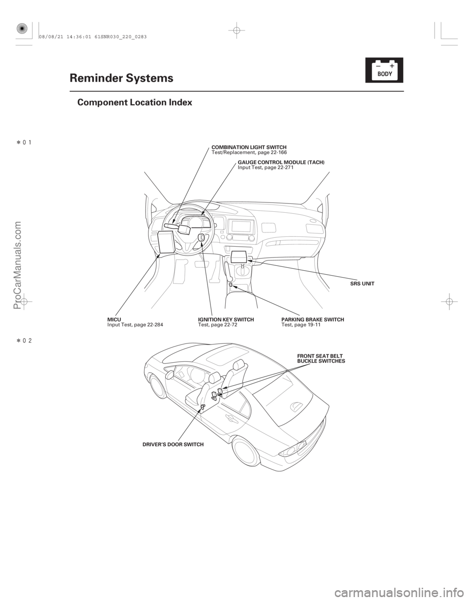
Component Location Index
GAUGE CONTROL MODULE (TACH)
MICU COMBINATION LIGHT SWITCH
IGNITION KEY SWITCH PARKING BRAKE SWITCH SRS UNIT
DRIVER’S DOOR SWITCH FRONT SEAT BELT
BUCKLE SWITCHES
Input Test, page 22-271
Input Test, page 22-284 Test/Replacement, page 22-166
Test, page 22-72 Test, page 19-11
08/08/21 14:36:01 61SNR030_220_0283
ProCarManuals.com
DYNOMITE -2009-
����
�(�#�'�������������������
�
�����������������)����
�µ�µ
�µ
22-282 Reminder Systems
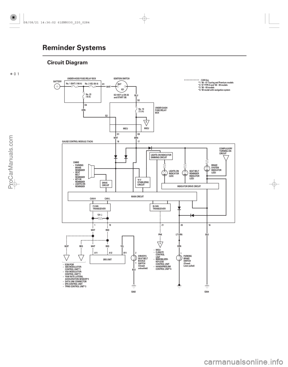
Circuit Diagram
MICU
ORN
(10 A) No. 23
BLK1 2
SRS UNIT
G602
B11
A12
A11 YEL
WHT REDRED
WHT
ORN28
LT GRN BLK16
G504
INDICATOR DRIVE CIRCUIT
MICU
ECM/PCM MAIN CIRCUIT
21
PNK
124
CAN L
CAN H
CHIME
WHT
BRN
RED 19
1
WHT No. 2 (IG) (50 A)
GAUGE CONTROL MODULE (TACH) 18
17
IG1
BAT
BLU
WHT
UNDER-HOOD FUSE/RELAY BOX
BATTERY IGNITION SWITCH
No. 1 (BAT) (100 A)
(7.5 A) No. 10UNDER-DASH
FUSE/RELAY
BOX
DRIVE
CIRCUIT
PARKING
BRAKE
REMINDER
SEAT
BELT
REMINDER
KEY-IN
REMINDER
F-CAN
TRANSCEIVER B-CAN
TRANSCEIVERLIGHTS-ON
INDICATOR
(LED)
IG1 HOT in ON (II)
and START (III)
ABS MODULATOR-
CONTROL UNIT*1 LIGHTS-ON INDICATOR
DIMMING CIRCUIT
PARKING
BRAKE
SWITCH
(Closed:
Lever pulled)
DRIVER’S
SEAT BELT
BUCKLE
SWITCH
(Closed:
unbuckled) SEAT BELT
REMINDER
INDICATOR
(LED)
BRAKE
SYSTEM
INDICATOR
(LED)COMPULSORY
TURNING-ON
CIRCUIT
LIGHTS-ON
REMINDER
CLIMATE
CONTROL
UNIT
IMMOBILIZER-
KEYLESS
CONTROL UNIT
HANDSFREELINK
CONTROL UNIT*4
H1
D4 D2
Q1 Q9
G2 :CANline
1
VSA MODULATOR-
CONTROL UNIT*2
YAW RATE-LATERAL
ACCELERATION SENSOR*2
DATA LINK CONNECTOR
EPS CONTROL UNIT
TPMS CONTROL UNIT*3 10 V
STABILIZING
CIRCUIT
*1: ’06 07 Touring and Premium models
*2: ’07 TYPE S and ’08 09 models
*3: ’08 09 models
*4: ’09 model with navigation system
MICU
A
B
08/08/21 14:36:02 61SNR030_220_0284
ProCarManuals.com
DYNOMITE -2009-
����
�(�#�'���������������������������������������)����
�µ
�µ
�µ
22-316Immobilizer System
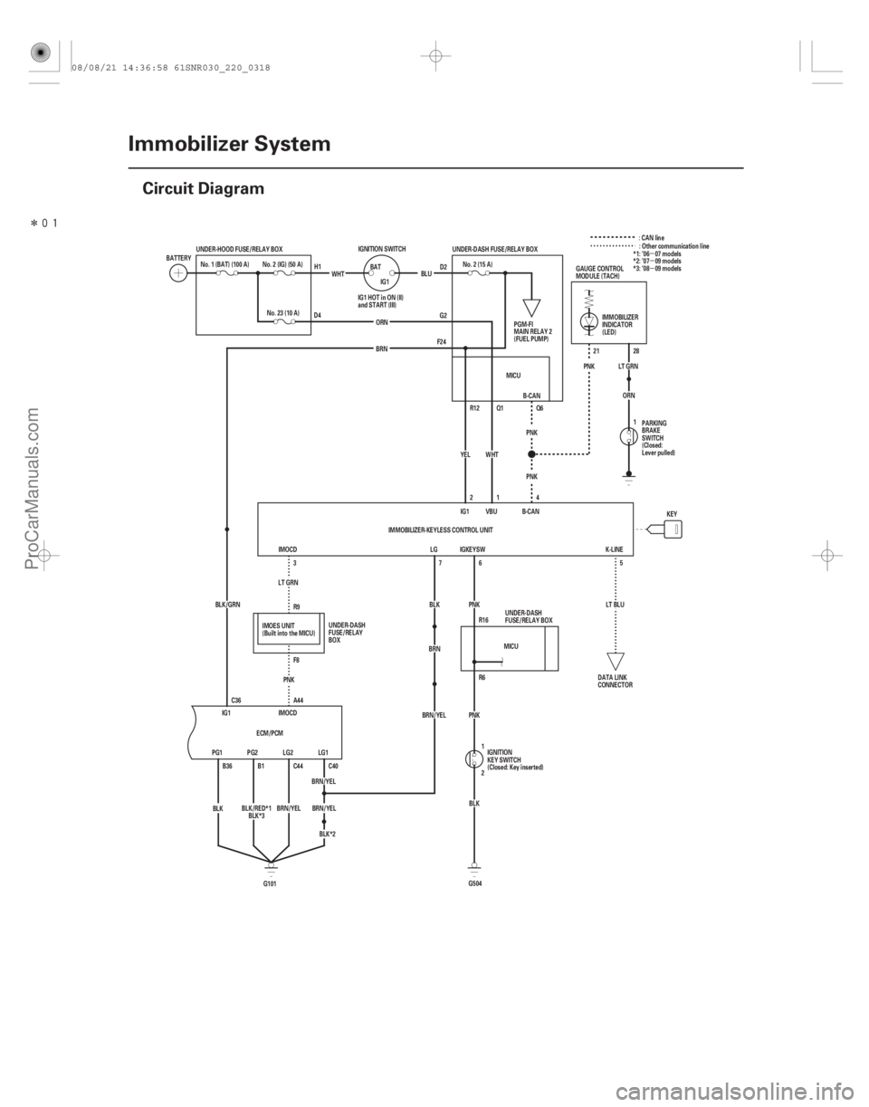
Circuit Diagram
LT GRN
PNK R9
F8 LT GRN
28
21
PNK
F24 G2D2
Q1
R12
PNK R6 R16 PNK
BRN/YEL C40
BRN/YEL LG1
LG2
BRN/YEL C44 B-CAN
Q6
G504 BLK
2 1
BRN/YEL IG1
2
YEL MICU
B-CAN
VBU
K-LINE
IGKEYSW
LG
7
BLK
BRN
IG1 C36
BLK/GRN
5
LT BLU
WHT
A44
B1
B36 PG2
PG1
BLK
G101 PNK
BRN
PNK
1
No. 2 (15 A)
WHT
KEY
IMOCD
ECM/PCM UNDER-DASH FUSE/RELAY BOX
ORN IG1
BAT
BLU
No. 23 (10 A)
UNDER-HOOD FUSE/RELAY BOX
No. 2 (IG) (50 A)
BATTERY IGNITION SWITCH
No. 1 (BAT) (100 A)
IMMOBILIZER-KEYLESS CONTROL UNIT6
3 4
PGM-FI
MAIN RELAY 2
(FUEL PUMP)
DATA LINK
CONNECTOR
IGNITION
KEY SWITCH
(Closed: Key inserted)
IG1 HOT in ON (II)
and START (III)
GAUGE CONTROL
MODULE (TACH)
UNDER-DASH
FUSE/RELAY BOX IMMOBILIZER
INDICATOR
(LED)
PARKING
BRAKE
SWITCH
(Closed:
Lever pulled)
UNDER-DASH
FUSE/RELAY
BOX
D4
H1
1: CAN line
: Other communication line
*1: ’06 07 models
*2: ’07 09 models
*3: ’08 09 models
ORN
IMOES UNIT
(Built into the MICU) MICU
BLK*2
IMOCD
BLK/RED*1 BLK*3
08/08/21 14:36:58 61SNR030_220_0318
ProCarManuals.com
DYNOMITE -2009-
���
Clear the DTC Memory Using MES
Connector Without the HDSTroubleshooting Intermittent Failures
Special Tools Required
24-24SRS
General Troubleshooting Information (cont’d)
B
A
07PAZ-001010A
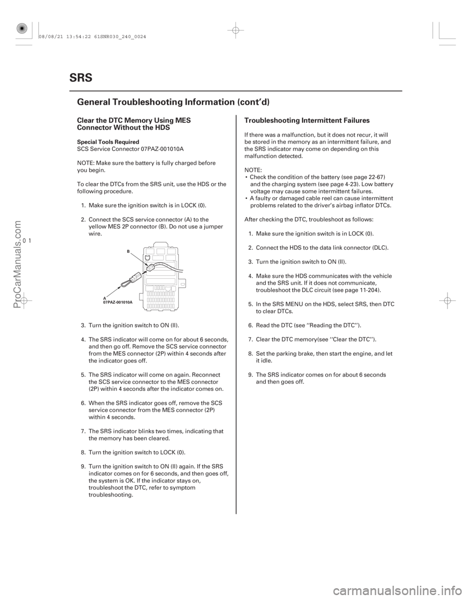
SCS Service Connector 07PAZ-001010A
NOTE: Make sure the battery is fully charged before
you begin.
To clear the DTCs from the SRS unit, use the HDS or the
following procedure. 1. Make sure the ignition switch is in LOCK (0).
2. Connect the SCS service connector (A) to the yellow MES 2P connector (B). Do not use a jumper
wire.
3. Turn the ignition switch to ON (II).
4. The SRS indicator will come on for about 6 seconds, and then go off. Remove the SCS service connector
from the MES connector (2P) within 4 seconds after
the indicator goes off.
5. The SRS indicator will come on again. Reconnect the SCS service connector to the MES connector
(2P) within 4 seconds after the indicator comes on.
6. When the SRS indicator goes off, remove the SCS service connector from the MES connector (2P)
within 4 seconds.
7. The SRS indicator blinks two times, indicating that the memory has been cleared.
8. Turn the ignition switch to LOCK (0).
9. Turn the ignition switch to ON (II) again. If the SRS indicator comes on for 6 seconds, and then goes off,
the system is OK. If the indicator stays on,
troubleshoot the DTC, refer to symptom
troubleshooting. If there was a malfunction, but it does not recur, it will
be stored in the memory as an intermittent failure, and
the SRS indicator may come on depending on this
malfunction detected.
NOTE:
Check the condition of the battery (see page 22-67) and the charging system (see page 4-23). Low battery
voltage may cause some intermittent failures.
A faulty or damaged cable reel can cause intermittent problems related to the driver’s airbag inflator DTCs.
After checking the DTC, troubleshoot as follows: 1. Make sure the ignition switch is in LOCK (0).
2. Connect the HDS to the data link connector (DLC).
3. Turn the ignition switch to ON (II).
4. Make sure the HDS communicates with the vehicle and the SRS unit. If it does not communicate,
troubleshoot the DLC circuit (see page 11-204).
5. In the SRS MENU on the HDS, select SRS, then DTC to clear DTCs.
6. Read the DTC (see ‘‘Reading the DTC’’).
7. Clear the DTC memory(see ‘‘Clear the DTC’’).
8. Set the parking brake, then start the engine, and let it idle.
9. The SRS indicator comes on for about 6 seconds and then goes off.
08/08/21 13:54:22 61SNR030_240_0024
ProCarManuals.com
DYNOMITE -2009-