Page 1555 of 2893
������(�#�'�����������
���������������������������)�
��
�´
19-62ABS Components
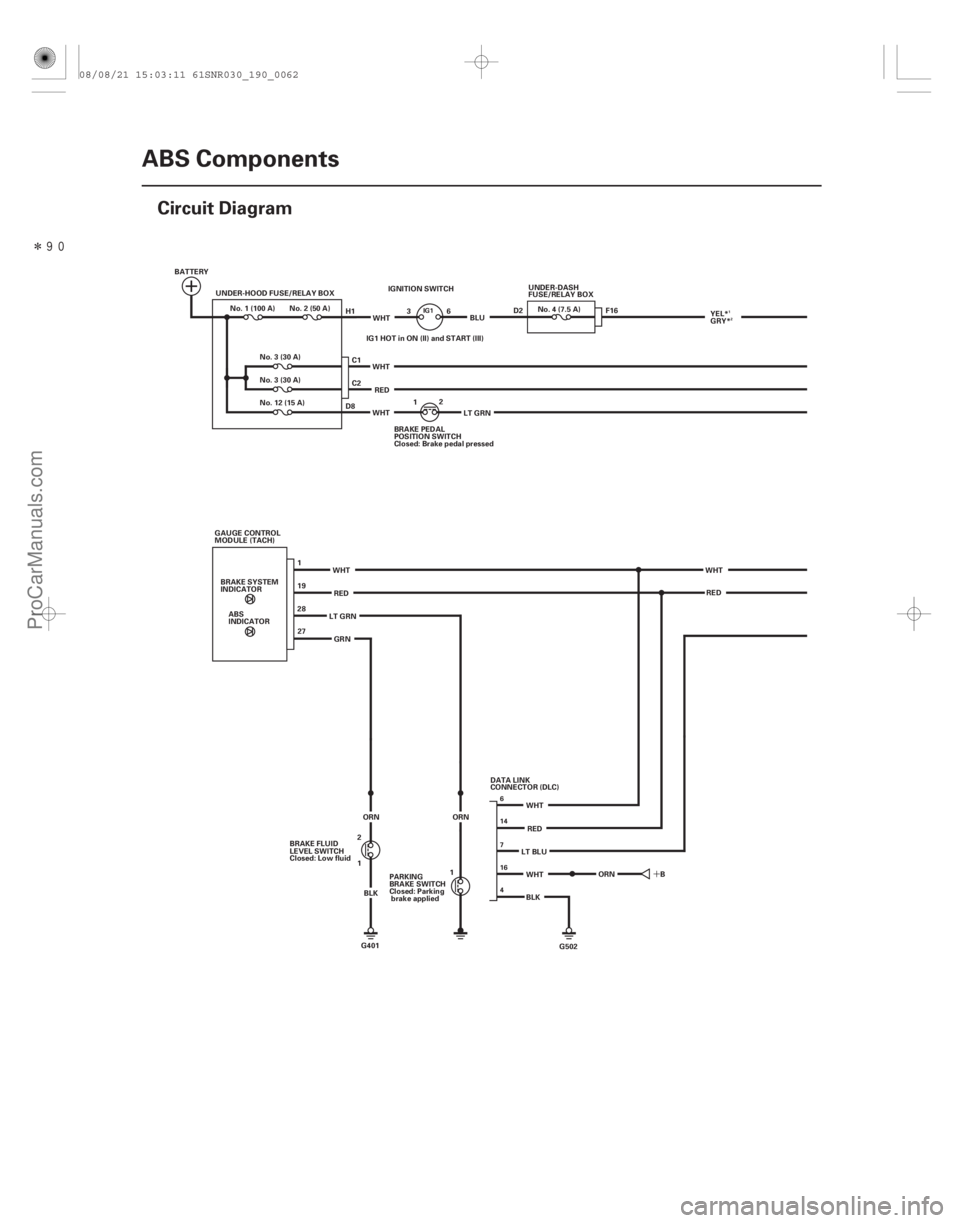
Circuit Diagram
BATTERY
UNDER-HOOD FUSE/RELAY BOX
1
19
2827
G502
BLK
WHT
RED
WHT
WHT
RED
ABS
INDICATOR
BRAKE SYSTEM
INDICATOR
GAUGE CONTROL
MODULE (TACH)
LT GRNGRN
LT BLUWHT
RED
IGNITION SWITCH
IG1 HOT in ON (II) and START (III) WHT
LT GRN
WHT
RED BLU
WHT BRAKE PEDAL
POSITION SWITCH
Closed: Brake pedal pressed1
2
C1
C2 UNDER-DASH
FUSE/RELAY BOX
No. 4 (7.5 A)
No. 3 (30 A)
No.1(100A) No.2(50A)
No. 3 (30 A)
No. 12 (15 A) F16
B
G401
BRAKE FLUID
LEVEL SWITCH
Closed: Low fluid
1 2
BLK
ORN
H1
D8
3
6
ORN
1
PARKING
BRAKE SWITCH
Closed: Parking
brake applied DATA LINK
CONNECTOR (DLC)D2
YEL*
GRY*
ORN
6
16
4 7 14
IG11
2
08/08/21 15:03:11 61SNR030_190_0062
ProCarManuals.com
DYNOMITE -2009-
Page 1557 of 2893
���
19-64ABS Components
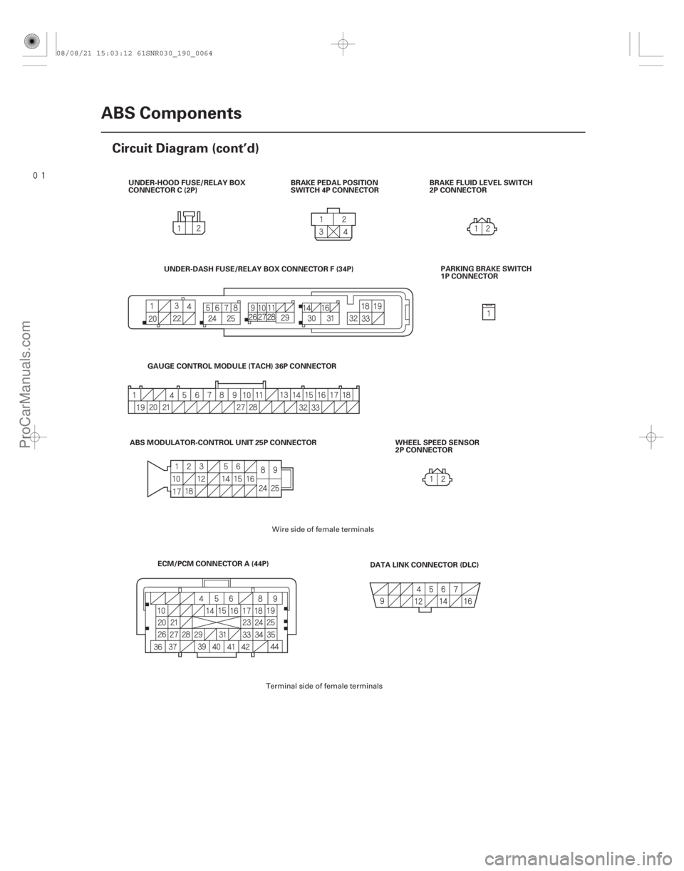
Circuit Diagram (cont’d)
UNDER-HOOD FUSE/RELAY BOX
CONNECTOR C (2P)
BRAKE PEDAL POSITION
SWITCH 4P CONNECTORBRAKE FLUID LEVEL SWITCH
2P CONNECTOR
DATA LINK CONNECTOR (DLC)
ECM/PCM CONNECTOR A (44P)
ABS MODULATOR-CONTROL UNIT 25P CONNECTOR PARKING BRAKE SWITCH
1P CONNECTOR
WHEEL SPEED SENSOR
2P CONNECTOR
UNDER-DASH FUSE/RELAY BOX CONNECTOR F (34P)
GAUGE CONTROL MODULE (TACH) 36P CONNECTOR
Wire side of female terminals
Terminal side of female terminals
08/08/21 15:03:12 61SNR030_190_0064
ProCarManuals.com
DYNOMITE -2009-
Page 1567 of 2893
����
�µ
�µ
�µ
�µ
�µ
�µ
YES
NO
DTC Appropriate Wheel
YES
NO
YES
NO
DTC 41-21:
DTC 42-21:
DTC 43-21:
DTC 44-21:
19-7419-74 ABS Components
DTC Troubles")
�(�#�'��������� �����
�������'���
���
�������)����
�µ
�µ
�µ
�µ
�µ
�µ
YES
NO
DTC Appropriate Wheel
YES
NO
YES
NO
DTC 41-21:
DTC 42-21:
DTC 43-21:
DTC 44-21:
19-7419-74 ABS Components
DTC Troubleshooting (cont’d)
4. Check for DTCs with the HDS.
Replace the ABS modulator-control unit
(see page 19-90).
Intermittent failure, the system is OK at this
time. The DTCs may be indicated under these conditions:
The vehicle goes into a spin.
The ABS continues to operate for a long time.
Snow, dirt, or debris build-up on the wheel speed sensor or magnetic encoder.
Misadjusted brake pedal position switch.
Contaminated brake fluid.
1. Raise the vehicle, and support it with safety stands in the proper locations (see page 1-11).
2. Turn the appropriate wheel by hand.
41-21 Right-front
42-21 Left-front
43-21 Right-rear
44-21 Left-rear
Repair the brake drag.
Go to step 3.
3. Check that the appropriate wheel speed sensor is properly mounted (see page 19-92).
Go to step 4.
Reinstall the wheel speed sensor, and check
the mounting position (see page 19-92).Right-front Wheel Lock
Left-front Wheel Lock
Right-rear Wheel Lock
Left-rear Wheel Lock
Is DT C 31-xx, 32-xx, 33-xx, 34-xx, 35-xx, 36-xx, 37 -x x , or 38-x x i nd i cat ed ?
Is there brake drag?Is t he w heel speed sensor i nst al l at i on OK ?
08/08/21 15:03:15 61SNR030_190_0074
ProCarManuals.com
DYNOMITE -2009-
Page 1581 of 2893
����
�µ
�µ
�µ
�µ �µ
�µ
�µ
�µ
ABS indicator and brake system indicator do
not go off
YES
NO
YES
NO YES
NO
YES
NO
19-88ABS Components")
����
�����
�(�#�'�����������
���������������������������)����
�µ
�µ
�µ
�µ �µ
�µ
�µ
�µ
ABS indicator and brake system indicator do
not go off
YES
NO
YES
NO YES
NO
YES
NO
19-88ABS Components
Symptom Troubleshooting
ABS MODULATOR-CONTROL UNIT 25P CONNECTOR
IG1 (YEL)*
*1: ’06 model
*2: ’07 model (GRY)*
ABS MODULATOR-CONTROL UNIT 25P CONNECTOR
IG1 (YEL)*
*1: ’06 model
*2: ’07 model (GRY)*
1
2
12
1. Turn the ignition switch to LOCK (0).
2. Check the No. 4 (7.5 A) fuse in the under-dash fuse/ relay box.
Go to step 3.
Reinstall the checked fuse, then go to step 8.
3. Disconnect the ABS modulator-control unit 25P connector (see step 2 on page 19-90).
4. Check for continuity between ABS modulator- control unit 25P connector terminal No. 16 and
body ground.
Repair short to body ground in the wire
between the No. 4 (7.5 A) fuse in the under-dash
fuse/relay box and the ABS modulator-control
unit.
Install a new No. 4 (7.5 A) fuse in the under-
dashfuse/relaybox,thengotostep5. 5. Reconnect the ABS modulator-control unit 25P
connector.
6. Turn the ignition switch to ON (II).
7. Check the ABS indicator and the brake system indicator for several sec onds when the ignition
switch is tuned to ON (II).
Troubleshooting is complete.
Replace the ABS modulator-control unit
(see page 19-90).
8. Disconnect the ABS modulator-control unit 25P connector (see step 2 on page 19-90).
9. Turn the ignition switch to ON (II).
10. Measure the voltage between ABS modulator- control unit 25P connector terminal No. 16 and
body ground.
Go to step 11.
Repair open in the wire between the No. 4
(7.5 A) fuse in the under-dash fuse/relay box and
the ABS modulator-control unit.
11. Turn the ignition switch to LOCK (0).
Wire side of female terminals
Wire side of female terminals
Isthefuseblown?
Is there continuity? Does t he i nd i cat or s come on t hen go of f ?
Is there battery voltage?
08/08/21 15:03:17 61SNR030_190_0088
ProCarManuals.com
DYNOMITE -2009-
Page 1583 of 2893
�
��
Removal
19-90ABS Components
ABS Modulator-Control Unit Removal and Installation
A
B C
15 N·m
(1.5 kgf·m, 11 lbf·ft)
D
E
I F
G
H 15 N·m
(1.5 k")
���
�(�#�'�����������
�����������
��������� �����)�
��
Removal
19-90ABS Components
ABS Modulator-Control Unit Removal and Installation
A
B C
15 N·m
(1.5 kgf·m, 11 lbf·ft)
D
E
I F
G
H 15 N·m
(1.5 kgf·m, 11 lbf·ft)
9.8 N·m
(1.0 kgf·m, 7.2 lbf·ft) 9.8 N·m
(1.0 kgf·m, 7.2 lbf·ft)
NOTE:
Do not spill brake fluid on the vehicle; it may damage the paint; if brake fluid gets on the paint, wash it off immediately with water.
Be careful not to damage or deform the brake lines during removal and installation.
Plug the ends of the hoses and the joints to prevent spilling brake fluid.
1. Turn the ignition switch to LOCK (0).
2. Disconnect the ABS modulator-control unit 25P connector (A) by pu lling up the lock (B); the connector disconnects
itself.
3. Disconnect the six brake lines from the ABS modulator-control unit. NOTE: Brake lines are connected to the master cylinder (C) and to the right-front (D), the left-rear (E), the right-rear
(F), and the left-front (G) brake systems.
4. Remove the ABS modulator-control unit (H) with the brackets (I) from the body.
5. Remove the ABS modulator-control unit from the brackets.
6. Separate the bracket if necessary.
08/08/21 15:03:18 61SNR030_190_0090
ProCarManuals.com
DYNOMITE -2009-
Page 1584 of 2893
Installation
19-91
1. Install the ABS modulator-control unit onto the brackets.
2. Install the bracket with the ABS modulator-control unit to the body.
3. Reconnect the six brake lines, then tighten the flare nuts to the specified torque.
4. Align the connecting surface of the ABS modulator-control unit 25P connector to the ABS modulator-control unit.
5. Lower the lock of the ABS modulator-control unit 25P connector, then confirm the connector is fully seated.
6. Bleed the brake system (see page 19-9).
7. Start the engine, and make sure the ABS indicator goes off.
8. Test-drive the vehicle, and make sure the ABS indicator does not come on.NOTE: If the brake pedal is spongy, there may be air trapped in the modulator which could then be induced into
the normal brake system during modulation. Bleed the brake system again (see page 19-9).
08/08/21 15:04:45 61SNR030_190_0091
ProCarManuals.com
DYNOMITE -2009-
Page 1587 of 2893

B
A
A
07AAG-SVBA100 B
07AAG-SVBA100
A
4. Apply multi-purpose grease to the wheel speedsensor O-ring (A) and the sen")
�����
����������
19-94ABS Components
Wheel Speed Sensor Replacement (cont’d)
B
A
A
07AAG-SVBA100 B
07AAG-SVBA100
A
4. Apply multi-purpose grease to the wheel speedsensor O-ring (A) and the sensor hole in the knuckle
(B).
5. Insert the guide pin tool (A) into the wheel speed sensor bolt hole until the shoulder of the tool
contacts the wheel speed sensor bracket.
NOTE: To prevent O-ring damage, the wheel speed
sensor must be installed with the guide pin tool. 6. Insert the wheel speed sensor (A) and the guide pin
tool (B) into the bolt hole on the knuckle.
NOTE: To ensure proper alignment when pushing
the wheel speed sensor into the knuckle housing,
do not hold the sensor bracket during installation,
hold the sensor wire.
7. Gently push and pull the wheel speed sensor in and out to make sure the O-ring is sliding properly in its
housing. While you are doing this, make sure the
sensor doesn’t come out of the knuckle assembly. If
the sliding effort is too high, remove the wheel
speed sensor, inspect the O-ring for damage, and
start the installation process again.
8. Remove the guide pin tool, then install the bolt, and tighten it to specified torque.
9. Clean the mating surfaces between the brake disc and the inside of the wheel, then install the front
wheel.
10. Start the engine, and make sure the ABS indicators go off.
11. Test-drive the vehicle, and make sure the ABS indicators do not come on.
08/08/21 15:04:46 61SNR030_190_0094
ProCarManuals.com
DYNOMITE -2009-
Page 1589 of 2893
����
System IndicatorABS Indicator
Brake System Indicator
VSA Indicator
VSA Activation Indicator
19-97
General Troubleshooting Information
A
D B
C
Thi")
���
�(�#�'���������������
�����������������������)����
System IndicatorABS Indicator
Brake System Indicator
VSA Indicator
VSA Activation Indicator
19-97
General Troubleshooting Information
A
D B
C
This system has four indicators:
ABS indicator (A)
Brake system indicator (B)
VSA indicator (C)
VSA activation indicator (D)
When the system is OK, each indicator comes on for
about 2 seconds after turning the ignition switch to
ON (II), then goes off.
When the system detects a problem, a DTC is set and,
depending upon the failure, the VSA modulator-control
unit determines which indicator(s) are turned on. If the
problem goes away (system returns to normal), the
indicator(s) are controlled in the following way
depending upon the DTC that is set: The indicator(s) come on and stay on when the ignition switch is ON (II).
The indicator(s) automatically go off.
The indicator(s) go off after the vehicle is driven. The ABS indicator comes on when the ABS function is
lost. The brakes still work like a conventional system.
The brake system indicator comes on when the EBD
function is lost, the parking brake is applied, and/or the
brake fluid level is low.
NOTE: If two or more wheel speed sensors fail, the
brake system indicator comes on.
The VSA indicator comes on when the VSA function is
lost.
The VSA activation indicator blinks when the VSA
function is activating. The VSA activation indicator
comes on and stays on when the VSA is turned OFF by
using the VSA OFF switch, or when the VSA function is
lost.
(cont’d)
08/08/21 15:04:50 61SNR030_190_0097
ProCarManuals.com
DYNOMITE -2009-