Page 1526 of 2893
����
19-34 Conventional Brake Components
Rear Brake Disc Replacement
B
10x1.25mm
74 N·m
(7.5 kgf·m,
54 lbf·ft)
A
8x1.25mm
22 N·m
(2.2 kgf�")
����
����
�(�#�'�����������
�����������
�������
� �����)����
19-34 Conventional Brake Components
Rear Brake Disc Replacement
B
10x1.25mm
74 N·m
(7.5 kgf·m,
54 lbf·ft)
A
8x1.25mm
22 N·m
(2.2 kgf·m,
16 lbf·ft)
C D C
8x1.25mm
A
6x1.0mm
9.8 N·m
(1.0 kgf·m,
7.2 lbf·ft)
B
NOTE: Keep any grease off the brake disc and brake
pads.
1. Raise the rear of the vehicle, and support it with safety stands in the proper locations (see page
1-11).
2. Remove the rear wheel.
3. Release the parking brake lever fully.
4. Remove the brake hose mounting bolt (A) from the bracket.
5. Remove the brake caliper bracket mounting bolts (B), then remove the caliper assembly (C) from the
knuckle. To prevent damage to the caliper
assembly or brake hose, use a short piece of wire
to hang the caliper assembly from the
undercarriage. Do not twist the brake hose and the
parking brake cable excessively.
NOTE: Make sure the washers (D) position on
reassembly, if they are removed (see step 5 on
page 18-32). 6. Remove the brake disc flathead screws (A).
7. Remove the brake disc (B) from the hub bearing
unit.
NOTE: If the brake disc is stuck to the hub bearing
unit, thread two 8 x 1.25 mm bolts (C) into the brake
disc to push it away from the hub bearing unit.
Turn each bolt 90 degrees at a time to prevent the
brake disc from binding.
8. Install the brake disc in the reverse order of removal, and note these items:
Before installing the brake disc, clean the mating surfaces between the hub bearing unit and the
inside of the brake disc.
Adjust the parking brake (see page 19-8).
9. Inspect the brake disc runout (see page 19-32).
10. Clean the mating surfaces between the brake disc and the inside of the wheel, then install the rear
wheel.
08/08/21 15:02:06 61SNR030_190_0034
ProCarManuals.com
DYNOMITE -2009-
Page 1527 of 2893
����
19-35
Rear Brake Caliper Overhaul
BRAKE HOSE8x1.0mm
23 N·m
(2.3 kgf·m, 17 lbf·ft)
SEALING WASHERS
BANJO BOLT
34 N·m
(3.5 kgf·m, 25 lbf·ft)")
���
�(�#�'�����������
�����������
�����
�
�!�����)����
19-35
Rear Brake Caliper Overhaul
BRAKE HOSE8x1.0mm
23 N·m
(2.3 kgf·m, 17 lbf·ft)
SEALING WASHERS
BANJO BOLT
34 N·m
(3.5 kgf·m, 25 lbf·ft)
BLEED SCREW
9 N·m (0.9 kgf·m, 7 lbf·ft)
CALIPER BODY
RODO-RING
SLEEVE PISTON
CUP ADJUSTING BOLT
BEARING A
SPACER
ADJUSTING SPRING B
PISTON BOOT
PISTON SEAL
PISTON
ASSEMBLY
CIRCLIP
SPRING
GUIDE
SHAFT
SHAFT COVER
LEVER ARM
SPRING
WASHER PARKING NUT
27 N·m
(2.8 kgf·m, 20 lbf·ft) RETURN
SPRING
23 N·m
(2.3 kgf·m,
17 lbf·ft)
INNER PAD
SHIM BRAKE PADS PAD SPRING
CALIPER PIN A CALIPER PIN B
PAD
RETAINERS
CALIPER
BRACKET
: Honda silicone grease (P/N 08C30-B0234M)
OUTER PAD SHIM
WEAR INDICATOR
CALIPER PIN PIN BOOT 10x1.25mm
74 N·m
(7.5 kgf·m, 54 lbf·ft)
Frequent inhalation of brake pad dust, regardless of material composition, could be hazardous to your health.
Avoid breathing dust particles.
Never use an air hose or brush to clean brake assemblies. Use an OSHA-approved vacuum cleaner.
Remove, disassemble, inspect, reassemble, and install the caliper, and note these items:
NOTE: Make sure that the caliper pins are installed correctly. Upper caliper pin B and lower caliper pin A are different.
If these caliper pins are installed in the wrong location, it will cause vibration, uneven or rapid pad wear, and possibly
uneven tire wear. Do not spill brake fluid on the vehicle; it may damage the paint; if brake fluid gets on the paint, wash it off immediately with water.
To prevent dripping brake fluid, cover disc onnected hose joints with rags or shop towels.
Clean all parts in brake fluid and air dry; blow out all passages with compressed air.
Before reassembling, check that all parts are free of dirt and other foreign particles.
Replace parts with new ones as specified in the illustration.
Make sure no dirt or other foreign matter gets into the brake fluid.
Make sure no grease or oil gets on the brake discs or pads.
When reusing brake pads, always reinstall them in their original positions to prevent loss of braking efficiency.
Do not reuse drained brake fluid. Use only clean Honda DOT 3 Brake Fluid from an unopened container. Using a non-Honda brake fluid can cause corrosion and shorten the life of the system.
Coat the piston, the piston seal groove, and the caliper bore with clean brake fluid.
Use recommended greases in the rear caliper set.
After installing the caliper, check the brake hose and line for leaks, interference, and twisting.
Replace.
Replace.
Replace. Replace.
Replace.
Replace.
Install inner pad
with its wear
indicator downward. Replace.
08/08/21 15:02:07 61SNR030_190_0035
ProCarManuals.com
DYNOMITE -2009-
Page 1528 of 2893
����
�(�#�'�����������
�����������
�������
� �����)����
19-36Conventional Brake Components
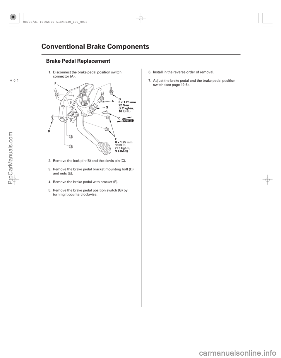
Brake Pedal Replacement
A
B CD
8x1.25mm
22 N·m
(2.2 kgf·m,
16 lbf·ft)
F
E
8x1.25mm
13 N·m
(1.3 kgf·m,
9.4 lbf·ft)
G
1. Disconnect the brake pedal position switch
connector (A).
2. Remove the lock pin (B) and the clevis pin (C).
3. Remove the brake pedal bracket mounting bolt (D) and nuts (E).
4. Remove the brake pedal with bracket (F).
5. Remove the brake pedal position switch (G) by turning it counterclockwise. 6. Install in the reverse order of removal.
7. Adjust the brake pedal and the brake pedal position
switch (see page 19-6).
08/08/21 15:02:07 61SNR030_190_0036
ProCarManuals.com
DYNOMITE -2009-
Page 1529 of 2893
����Connection
Point Component Connected to Specified Torque Value Note
19-37
Brake Hose and Line Inspection
A B
C DFC
A C
B
C
E
1. Inspect the brake")
���
�(�#�'�����������
�����������
�������
�"�����)����Connection
Point Component Connected to Specified Torque Value Note
19-37
Brake Hose and Line Inspection
A B
C DFC
A C
B
C
E
1. Inspect the brake hoses for damage, deterioration, leaks, interference, and twisting.
2. Check the brake lines for damage, rusting, and leaks. Also check for bent brake lines.
3. Check for leaks at hose and line joints and connections, and retighten if necessary.
4. Check the master cylinder and the ABS or VSA modulator-control unit for damage and leaks. A Front brake caliper Brake hose 34 N·m (3.5 kgf·m, 25 lbf·ft) Banjo bolt Bleed screw 9 N·m (0.9 kgf·m, 7 lbf·ft)
B Rear brake caliper Brake hose 34 N·m (3.5 kgf·m, 25 lbf·ft) Banjo bolt Bleed screw 9 N·m (0.9 kgf·m, 7 lbf·ft)
C Brake hose Brake line 15 N·m (1.5 kgf·m, 11 lbf·ft) Flare nut
D Master cylinder (ABS) Brake line 15 N·m (1.5 kgf·m, 11 lbf·ft) Flare nut Master cylinder (VSA) 22 N·m (2.2 kgf·m, 16 lbf·ft)
E ABS modulator-control unit Brake line 15 N·m (1.5 kgf·m, 11 lbf·ft) Flare nut VSA modulator-control unit Brake line (10 mm nut)15 N·m (1.5 kgf·m, 11 lbf·ft)
Brake line
(12 mm nut) 22 N·m (2.2 kgf·m, 16 lbf·ft)
F 4-way joint Brake line 15 N·m (1.5 kgf·m, 11 lbf·ft) Flare nut
08/08/21 15:02:08 61SNR030_190_0037
ProCarManuals.com
DYNOMITE -2009-
Page 1530 of 2893
����
19-38 Conventional Brake Components
Brake Hose Replacement
A
B
C
AB
C A
DB
C
NOTE: Before reassembling, check that all parts are fre")
����
�����
�(�#�'�����������
�����������
�������
� �����)����
19-38 Conventional Brake Components
Brake Hose Replacement
A
B
C
AB
C A
DB
C
NOTE: Before reassembling, check that all parts are free of dirt and other foreign particles.
Replace parts with new ones whenever specified to do so.
Do not spill brake fluid on the vehicle; it may damage the paint; if brake fluid gets on the paint, wash it off
immediately with water.
Plug the ends of the hoses and the joints to prevent spilling brake fluid.
The illustrations show only the front of the vehicle except where the procedure is different for the rear.
1. Remove the wheel.
2. Disconnect the brake hose (A) from the brake line (B) using a 10 mm flare-nut wrench (C). 3. Front: Remove the brake hose clip (A) from the
brake hose (B).
4. Remove the banjo bolt (C), and disconnect the brake hose from the caliper.
5. Remove the brake hose mounting bolt(s) (D), then remove the brake hose.
NOTE: Rear: Remove the brake hose with the
bracket.
Replace.
08/08/21 15:02:08 61SNR030_190_0038
ProCarManuals.com
DYNOMITE -2009-
Page 1531 of 2893

C
10x1.0mm
34 N·m
(3.5 kgf·m,
25 lbf·ft)
D A
A
B
C
E
10x1.0mm
15 N·m
(1.5 kgf·m,
11 lbf·ft)
D
A 8 x 1.25 mm
22 N·m
(2.")
��������
����
Front
Rear
19-39
B
8x1.25mm
22 N·m
(2.2 kgf·m,
16 lbf·ft)
C
10x1.0mm
34 N·m
(3.5 kgf·m,
25 lbf·ft)
D A
A
B
C
E
10x1.0mm
15 N·m
(1.5 kgf·m,
11 lbf·ft)
D
A 8 x 1.25 mm
22 N·m
(2.2 kgf·m,
16 lbf·ft)
E
10x1.0mm
15 N·m
(1.5 kgf·m,
11 lbf·ft)
6. Install the brake hose (A) with the brake hose
mounting bolt (B).
7. Connect the brake hose to the caliper with the banjo bolt (C) and the new sealing washers (D). 8. Position the brake hose ends (A).
NOTE: Front: Install the brake hose on the brake hose bracket (B) with a new brake hose clip (C).
Rear: Install the brake hose bracket (D) to the frame.
9. Connect the brake line (E) to the brake hose.
10. After installing the brake hose, bleed the brake system (see page 19-9).
11. Do the following checks: Check the brake hose and line joint for leaks, andtighten if necessary.
Check the brake hoses for interference and twisting.
12. Clean the mating surfaces between the brake disc and the inside of the wheel, then install the wheel.
Replace.
Replace.
08/08/21 15:02:09 61SNR030_190_0039
ProCarManuals.com
DYNOMITE -2009-
Page 1532 of 2893
����
�(�#�'���������������������������
�
�
� �����)����
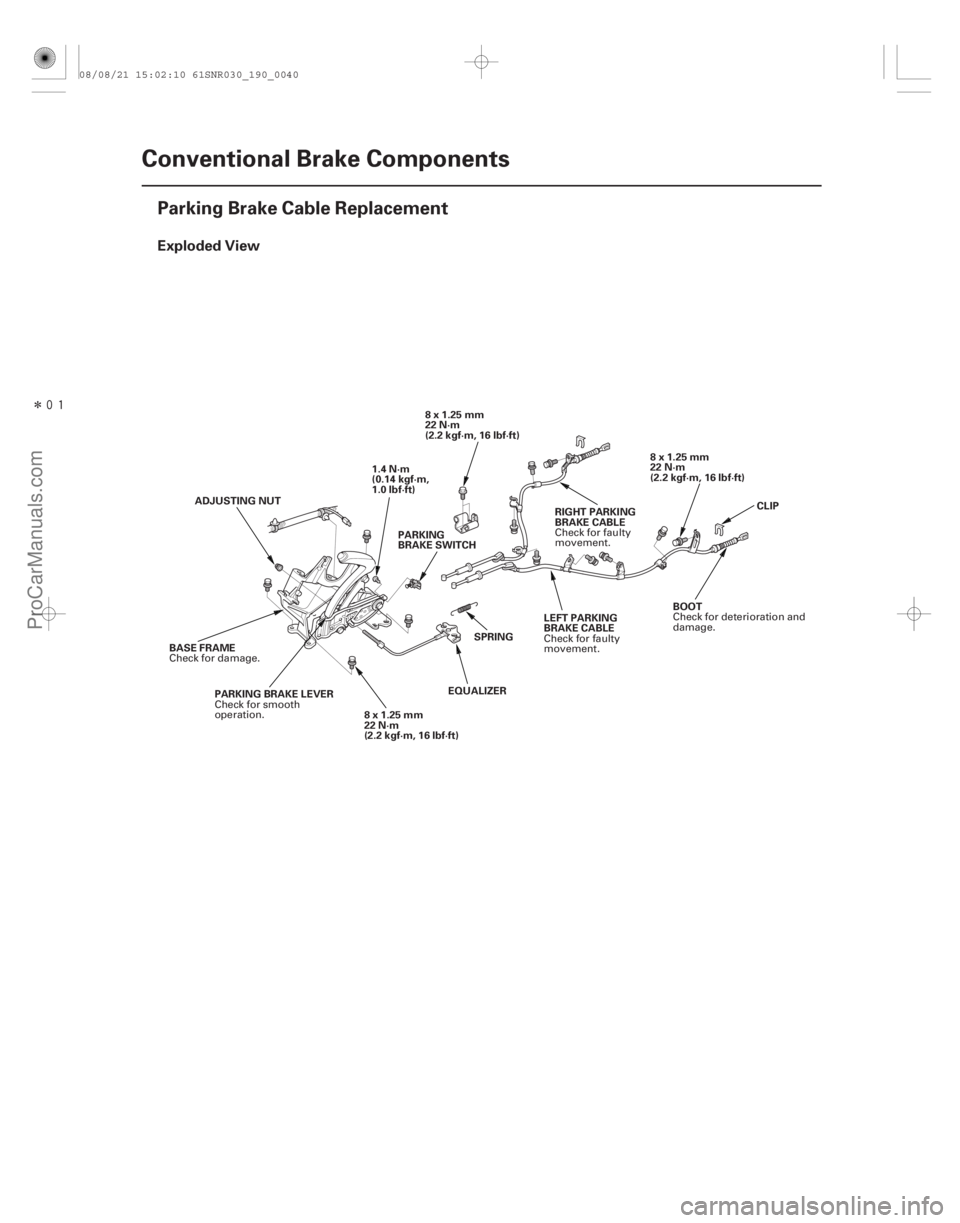
Exploded View
19-40Conventional Brake Components
Parking Brake Cable Replacement
1.4 N·m
(0.14 kgf·m,
1.0 lbf·ft)
PARKING
BRAKE SWITCH 8 x 1.25 mm
22 N·m
(2.2 kgf·m, 16 lbf·ft)
8x1.25mm
22 N·m
(2.2 kgf·m, 16 lbf·ft)
RIGHT PARKING
BRAKE CABLE
LEFT PARKING
BRAKE CABLE
SPRING
EQUALIZER
ADJUSTING NUT
PARKING BRAKE LEVER
BASE FRAME
8x1.25mm
22 N·m
(2.2 kgf·m, 16 lbf·ft) CLIP
BOOT
Check for faulty
movement.
Check for faulty
movement.
Check for smooth
operation.
Check for damage.
Check for deterioration and
damage.
08/08/21 15:02:10 61SNR030_190_0040
ProCarManuals.com
DYNOMITE -2009-
Page 1533 of 2893
����
Removal
Lever Grip
19-4119-41
Parking Brake Lever Grip and Cover
Replacement
A
B
C
D AB
C
D B
A
C
NOTE: The parking brake cables m")
��������
���
�(�#�'���������������������������
���
� �����)����
Removal
Lever Grip
19-4119-41
Parking Brake Lever Grip and Cover
Replacement
A
B
C
D AB
C
D B
A
C
NOTE: The parking brake cables must not be bent or distorted. This will lead to stiff operation and
premature failure.
Refer to the Exploded View as needed during this procedure.
1. Release the parking brake lever fully.
2. Loosen the parking brake cable adjusting nut (see page 19-8).
3. Remove the parking brake cable clip (A) from the brake cable (B).
4. Disconnect the parking brake cable from the l ever
(C).
5. Remove the parking brake cable mounting hardware, then remove the cable.
6. Install the parking brake cable in the reverse order of removal, and note these items:
Be careful not to bend or distort the cable and boot (D).
Make sure the parking brake cable clip is fully seated on the cable housing.
Adjust the parking brake (see page 19-8). 1. Remove the center console (see page 20-92).
2. Pull up the parking brake fully (8 to 10 clicks).
3. Start at the front edge (A), peel lever grip away
from lever cap (B). Continue to peel the grip from
the lever to gain access to the hooks (C).
4. Push in both sides of the hook (A) on the l ever cap
(B), and remove the lever cap and the pushrod (C)
with the knob (D).
(cont’d)
Replace.Replace.
08/08/21 15:02:10 61SNR030_190_0041
ProCarManuals.com
DYNOMITE -2009-