Page 1534 of 2893
����
Removal
Lever Grip
19-4119-41
Parking Brake Lever Grip and Cover
Replacement
A
B
C
D AB
C
D B
A
C
NOTE: The parking brake cables m")
��������
���
�(�#�'���������������������������
���
� �����)����
Removal
Lever Grip
19-4119-41
Parking Brake Lever Grip and Cover
Replacement
A
B
C
D AB
C
D B
A
C
NOTE: The parking brake cables must not be bent or distorted. This will lead to stiff operation and
premature failure.
Refer to the Exploded View as needed during this procedure.
1. Release the parking brake lever fully.
2. Loosen the parking brake cable adjusting nut (see page 19-8).
3. Remove the parking brake cable clip (A) from the brake cable (B).
4. Disconnect the parking brake cable from the l ever
(C).
5. Remove the parking brake cable mounting hardware, then remove the cable.
6. Install the parking brake cable in the reverse order of removal, and note these items:
Be careful not to bend or distort the cable and boot (D).
Make sure the parking brake cable clip is fully seated on the cable housing.
Adjust the parking brake (see page 19-8). 1. Remove the center console (see page 20-92).
2. Pull up the parking brake fully (8 to 10 clicks).
3. Start at the front edge (A), peel lever grip away
from lever cap (B). Continue to peel the grip from
the lever to gain access to the hooks (C).
4. Push in both sides of the hook (A) on the l ever cap
(B), and remove the lever cap and the pushrod (C)
with the knob (D).
(cont’d)
Replace.Replace.
08/08/21 15:02:10 61SNR030_190_0041
ProCarManuals.com
DYNOMITE -2009-
Page 1535 of 2893
��������
Lever Cover
19-42 Conventional Brake Components
Parking Brake Lever Grip and Cover Replacement (cont’d)
A
A
B
5. Remove the lever grip (A) by sliding it up. 6. Remove the clip (A) on the driver’s side of theparking brake lever cover (B).
7. Separate the parking brake lever covers, and remove them.
08/08/21 15:02:10 61SNR030_190_0042
ProCarManuals.com
DYNOMITE -2009-
Page 1536 of 2893
��������
����
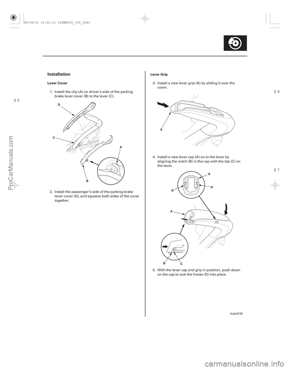
Installation
Lever CoverLever Grip
19-43
A
B
D
C A
AD
D
A
B C
1. Install the clip (A) on driver’s side of the parking
brake lever cover (B) to the lever (C).
2. Install the passenger’s side of the parking brake lever cover (D), and squeeze both sides of the cover
together. 3. Install a new lever grip (A) by sliding it over the
cover.
4. Install a new lever cap (A) on to the lever by aligning the notch (B) in the cap with the tab (C) on
the lever.
5. With the lever cap and grip in position, push down on the cap to lock the hooks (D) into place.
(cont’d)
08/08/21 15:02:11 61SNR030_190_0043
ProCarManuals.com
DYNOMITE -2009-
Page 1537 of 2893
��������
19-44Conventional Brake Components
Parking Brake Lever Grip and Cover Replacement (cont’d)
A
B C
B
A
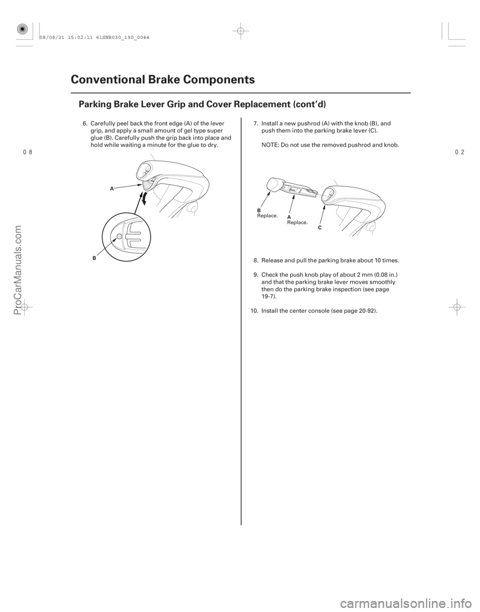
6. Carefully peel back the front edge (A) of the levergrip, and apply a small amount of gel type super
glue (B). Carefully push the grip back into place and
hold while waiting a minute for the glue to dry. 7. Install a new pushrod (A) with the knob (B), and
push them into the parking brake lever (C).
NOTE: Do not use the removed pushrod and knob.
8. Release and pull the parking brake about 10 times.
9. Check the push knob play of about 2 mm (0.08 in.) and that the parking brake lever moves smoothly
then do the parking brake inspection (see page
19-7).
10. Install the center console (see page 20-92).
Replace. Replace.
08/08/21 15:02:11 61SNR030_190_0044
ProCarManuals.com
DYNOMITE -2009-
Page 1538 of 2893
����
���� �����
�(�#�'�����������
�����������
��������� �����)����
19-45
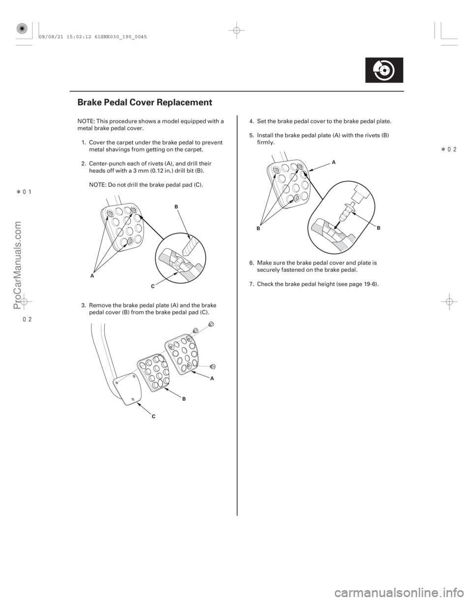
Brake Pedal Cover Replacement
A B
C
A
B
C A
B
B
NOTE: This procedure shows a model equipped with a
metal brake pedal cover.
1. Cover the carpet under the brake pedal to pr event
metal shavings from getting on the carpet.
2. Center-punch each of rivets (A), and drill their heads off with a 3 mm (0.12 in.) drill bit (B).
NOTE: Do not drill the brake pedal pad (C).
3. Remove the brake pedal plate (A) and the brake pedal cover (B) from the brake pedal pad (C). 4. Set the brake pedal cover to the brake pedal plate.
5. Install the brake pedal plate (A) with the rivets (B)
firmly.
6. Make sure the brake pedal cover and plate is securely fastened on the brake pedal.
7. Check the brake pedal height (see page 19-6).
08/08/21 15:02:12 61SNR030_190_0045
ProCarManuals.com
DYNOMITE -2009-
Page 1540 of 2893
����
Brakes
....................................
Conventional Brake Components . 19-1
ABS (Anti-lock Brake System)
Components (’06-07 Models)
..........")
�(�#�'�������������������������
�������/�����)����
Brakes
....................................
Conventional Brake Components . 19-1
ABS (Anti-lock Brake System)
Components (’06-07 Models)
...................... ......................
VSA (Vehicle Stability Assist) System
Components (’07-09 Models) . 19-95
........................................
......................
....................................... ..............................
.....................................................
............................................................ ..........................................................................................
........................................ ...........................
Component Location Index
. 19-48
General Troubleshooting Information . 19-49
DTC Troubleshooting Index . 19-52
Symptom Troubleshooting Index . 19-55
System Description . 19-56
Circuit Diagram . 19-62
DTC Troubleshooting . 19-65
Symptom Troubleshooting . 19-88
ABS Modulator-Control Unit Removal and Installation . 19-90
Wheel Speed Sensor Replacement . 19-92
08/08/21 15:02:12 61SNR030_190_0047
ProCarManuals.com
DYNOMITE -2009-
Page 1542 of 2893
�
��
System IndicatorABS Indicator
Brake System Indicator
19-49
General Troubleshooting Information
AB
This system has two indicators: ABS indicator")
���
�(�#�'�����������
���������������������������)�
��
System IndicatorABS Indicator
Brake System Indicator
19-49
General Troubleshooting Information
AB
This system has two indicators: ABS indicator (A)
Brake system indicator (B)
When the system is OK, each indicator comes on for
about 2 seconds after turning the ignition switch to
ON (II), then goes off.
When the system detects a problem, a DTC is set and,
depending upon the failure, the ABS modulator-control
unit determines which indicator(s) are turned on. If the
problem goes away (system returns to normal), the
indicator(s) are controlled in the following way
depending upon the DTC that is set: The indicator(s) come on and stay on when the ignition switch is ON (II).
The indicator(s) automatically go off.
The indicator(s) go off after the vehicle is driven. The ABS indicator comes on when the ABS function is
lost. The brakes still work like a conventional system.
The brake system indicator comes on when the EBD
function is lost, the parking brake is applied, and/or the
brake fluid level is low.
NOTE: If two or more wheel speed sensors fail, the
brake system indicator comes on.
(cont’d)
08/08/21 15:02:15 61SNR030_190_0049
ProCarManuals.com
DYNOMITE -2009-
Page 1543 of 2893

Self-diagnosis
Kickback
Pump Motor
Brake Fluid Replacement/Air BleedingHow to Troubleshoot DTCs
Intermittent Failures
19-50
ABS Components
General Troubleshooting Informa")
Diagnostic Trouble Code (DTC)
Self-diagnosis
Kickback
Pump Motor
Brake Fluid Replacement/Air BleedingHow to Troubleshoot DTCs
Intermittent Failures
19-50
ABS Components
General Troubleshooting Information (cont’d)
The memory holds all DTCs. However, when the
same DTC is detected more than once, the more
recent DTC is written over the earlier one. Therefore,
when the same problem is detected repeatedly, it is
memorized as a single DTC.
The DTCs are indicated in the order they occur.
The DTCs are memorized in the EEPROM. Therefore, the memorized DTCs cannot be erased by
disconnecting the battery. Do the specified
procedures to clear the DTCs.
Self-diagnosis can be classified into two categories: – Initial diagnosis: Done right after the ignition switch is turned to ON (II) and until the ABS indicator goes
off.
– Regular diagnosis: Done right after the initial diagnosis until the ignition switch is turned to
LOCK (0).
When the system detects a problem, the ABS modulator-control unit shifts to fail-safe mode.
The pump motor operates when the ABS modulator-
control unit is functioning, and the fluid in the reservoir
is forced out to the master cylinder, causing kickback at
the brake pedal. The pump motor operates when the ABS modulator- control unit is functioning.
The ABS modulator-control unit checks the pump motor operation one time after completing initial
diagnosis during regular diagnosis when the vehicle
is driven over 15 km/h (10 mph).
Brake fluid replacement and air bleeding procedures
are identical to the procedures used on vehicles without
ABS (see page 19-9). The troubleshooting procedures assume that the cause
of the problem is still present, and the ABS indicator is
still on. Following a troubleshooting procedure for a
code that has been cleared but does not reset can result
in incorrect diagnosis.
1. Question the client about the conditions when the problem occurred, and try to reproduce the same
conditions for troubleshooting. Find out when the
ABS indicator came on, such as during activation,
after activation, when the vehicle was traveling at a
certainspeed,etc.Ifnecessary,havetheclient
demonstrate the concern.
2. When the ABS indicator does not come on during the test-drive, check for loose connectors, poor
contact of the terminals, etc. in the circuit indicated
by the DTC before you start troubleshooting.
3. After troubleshooting, or the repairs are done, clear the DTCs, and test-drive the vehicle under the same
conditions that originally set the DTCs. Make sure
the ABS indicator does not come on.
4. Check for DTCs from other systems which are connected via F-CAN. If there are DTCs that are
related to F-CAN, one possible cause was that the
ignition switch was turned to ON (II) with the ABS
modulator-control unit connector disconnected.
Clear the DTCs. Check for fuel and emissions DTC’s
first.
NOTE: Always troubleshoot fuel and emissions
DTC’s first.
The term ‘‘intermittent failure’’ means a system may
have had a failure, but it checks OK now. If you cannot
reproduce the condition, check for loose connectors or
terminal pins related to the circuit that you are
troubleshooting.
08/08/21 15:02:15 61SNR030_190_0050
ProCarManuals.com
DYNOMITE -2009-