Page 795 of 2893
����
�(�#�'���������������
�����
�����������!�����)����
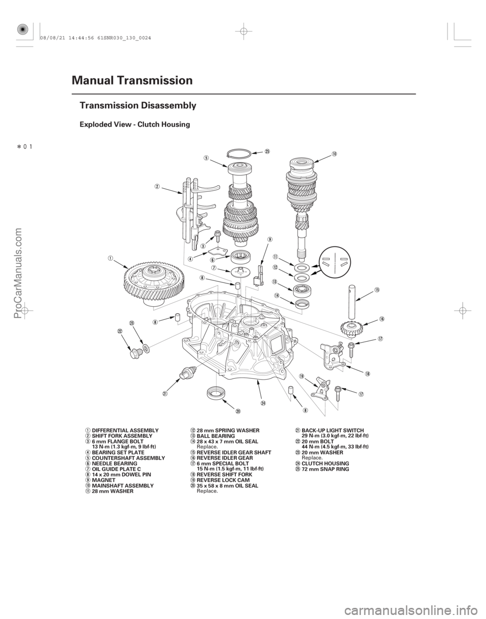
Exploded View - Clutch Housing
13-22Manual Transmission
Transmission Disassembly
MAINSHAFT ASSEMBLY COUNTERSHAFT ASSEMBLY
REVERSE IDLER GEAR
REVERSE LOCK CAM BALL BEARING
REVERSE IDLER GEAR SHAFT
14x20mmDOWELPIN
MAGNET DIFFERENTIAL ASSEMBLY
OIL GUIDE PLATE C BEARING SET PLATE
NEEDLE BEARING
28 mm WASHER 28 mm SPRING WASHER
REVERSE SHIFT FORK
SHIFT FORK ASSEMBLY
CLUTCH HOUSING
72 mm SNAP RING
6 mm FLANGE BOLT
13 N·m (1.3 kgf·m, 9 lbf·ft)
35x58x8mmOILSEAL 28x43x7mmOILSEAL20 mm WASHER BACK-UP LIGHT SWITCH
29 N·m (3.0 kgf·m, 22 lbf·ft)
20 mm BOLT
44 N·m (4.5 kgf·m, 33 lbf·ft)
6mmSPECIALBOLT
15 N·m (1.5 kgf·m, 11 lbf·ft)
Replace. Replace. Replace.
08/08/21 14:44:56 61SNR030_130_0024
ProCarManuals.com
DYNOMITE -2009-
Page 796 of 2893

10 mm SEALING WASHER
FILLER PLUG
44 N·m (4.5 kgf·m, 33 lbf·ft)
40x56x8mmOIL")
�����
Exploded View - Transmission Housing
13-23
TRANSMISSION HOUSING32 mm SEALING CAP
34 N·m (3.5 kgf·m, 25 lbf·ft)
10 mm SEALING WASHER
FILLER PLUG
44 N·m (4.5 kgf·m, 33 lbf·ft)
40x56x8mmOILSEAL
10 mm FLANGE BOLT
44 N·m (4.5 kgf·m, 33 lbf·ft)
14 mm SEALING WASHER
TRANSMISSION HANGER A 8 mm FLANGE BOLT
27 N·m (2.8 kgf·m, 20 lbf·ft)
INTERLOCK BOLT
39 N·m (4.0 kgf·m, 29 lbf·ft)
OIL GUIDE PLATE M
72 mm SHIM
OIL GUTTER PLATE
DRAIN PLUG
39 N·m (4.0 kgf·m, 29 lbf·ft) 20 mm SEALING WASHER STEEL BALL SPRING
TRANSMISSION HANGER B DETENT BOLT
22 N·m (2.2 kgf·m, 16 lbf·ft)
12 mm SEALING WASHER
HARNESS BRACKET A
6 x 30 mm FLANGE BOLT
12 N·m (1.2 kgf·m, 9 lbf·ft) 8x14mmDOWELPIN
CHANGE LEVER ASSEMBLY TRANSMISSION HANGER
10 mm FLANGE BOLT
44 N·m (4.5 kgf·m, 33 lbf·ft)
PLAIN WASHER
6 x 20 mm FLANGE BOLT
12 N·m (1.2 kgf·m, 9 lbf·ft) 6 mm FLANGE BOLT
12 N·m (1.2 kgf·m, 9 lbf·ft) OUTPUT SHAFT (COUNTERSHAFT)
SPEED SENSOR
O-RING
80 mm SHIM
(cont’d)
Replace.
Replace.
Replace. Replace. Replace. Replace.
08/08/21 14:44:57 61SNR030_130_0025
ProCarManuals.com
DYNOMITE -2009-
Page 799 of 2893
�����
������
��
�
��
13-26Manual Transmission
Transmission Disassembly (cont’d)
A
D
E B
C
F A B
A
A B
M
12. Remove the reverse shift fork (A).
13. Apply tape to the mainshaft splines to protect the seal, then remove the mainshaft assembly (A) and
the countershaft assembly (B) with the shift fork
assembly (C) from the clutch housing (D).
14. Remove the 28 mm spring washer (E) and the 28 mm washer (F). 15. Remove the differential assembly (A) and the
magnet (B).
16. Remove the oil gutter plate (A), the 72 mm shim (B), and oil guide plate M.
08/08/21 14:45:00 61SNR030_130_0028
ProCarManuals.com
DYNOMITE -2009-
Page 801 of 2893
���
�(�#�'���������������
���������������
�"�����)����
13-28Manual Transmission
Change Lever Assembly Disassembly/Reassembly
BREATHER CAP
6x1.0mm
12 N·m
(1.2 kgf·m, 9 lbf·ft)
ROLLER
WASHER
5TH SELECT
SPRING
SELECT STOP
PLATE SHIFT ARM
COVER
INTERLOCK REVERSE LOCK CAM
STRIKER8 mm SPRING WASHER
8mmSPECIALBOLT
31 N·m
(3.2 kgf·m, 23 lbf·ft)
DUST COVER CHANGE LEVER
CHANGE LEVER COVER
SELECT LEVER
DUST SEAL
1ST/2ND SELECT
SPRING SHIFT ARM
OIL SEAL
(P/N 08798-9002)
(P/N 08798-9002)
(P/N 08798-9002)
NOTE: Prior to reassembling, clean all the parts in solvent, dry them, and apply grease to the contact surfaces as
shown.
Turn toward the front of
the vehicle, then install it. Be careful not to damage the
dust seal when installing it.
Replace.
Replace.
08/08/21 14:45:01 61SNR030_130_0030
ProCarManuals.com
DYNOMITE -2009-
Page 828 of 2893
����
Special Tools Required
13-52
Manual Transmission
Mainshaft Bearing and Oil Seal Replacement
C
07736-A01000B
D
B")
�µ
�µ
����
����� ����
�����
�(�#�'���������������
���������������
� �����)����
Special Tools Required
13-52
Manual Transmission
Mainshaft Bearing and Oil Seal Replacement
C
07736-A01000B
D
B
A
A A
07749-0010000
B
07746-0010300
A
07JAD-PL90100
Oil seal driver, 65 mm 07JAD-PL90100
Adjustable bearing puller, 20 40 mm 07736-A01000B
Bearing driver attachment, 42 x 47 mm 07746-0010300
Driver handle, 15 x 135L 07749-0010000
Slide hammer, 3/8’’-16 UNF commercially available 1. Remove the ball bearing (A) from the clutch housing (B) using the 20 40 mm adjustable
bearing puller (C) and a commercially available
3/8’’ - 16 UNF slide hammer (D).
2. Remove the oil seal (A) from the clutch housing. Be careful when removing the oil seal so the clutch
housing is not damaged. 3. Drive in new oil seal from the transmission side
using the 15 x 135L driver handle (A) and the
42 x 47 mm bearing driver attachment (B).
4. Drive in new ball bearing from the transmission side using the 65 mm oil seal driver (A).
08/08/21 14:45:49 61SNR030_130_0054
ProCarManuals.com
DYNOMITE -2009-
Page 829 of 2893
�µ
�µ
���
����
����
�����
�(�#�'���������������
�������
�������
� �����)����
Special Tools Required
13-53
Countershaft Bearing Replacement
A
B
A
B
07736-A01000B D
C D
07JAD-PL90100
A
C
B
B
6x1.0mm
12 N·m
(1.2 kgf·m, 8.7 lbf·ft) A
Oil seal driver, 65 mm 07JAD-PL90100
Adjustable bearing puller, 20 40 mm 07736-A01000B
Slide hammer, 3/8’’-16 UNF commercially available
1. Remove the bearing set plate (A) from the clutch housing (B).
2. Remove the needle bearing (A) using the 20 40 mm adjustable bearing puller (B) and a
commercially available 3/8’’-16 UNF slide hammer
(D), then remove oil guide plate C. 3. Position oil guide plate C and new needle bearing
(A) in the bore of the clutch housing (B).
4. Install the needle bearing using the 65 mm oil seal driver (D).
5. Install the bearing set plate (A) with the bolts (B).
08/08/21 14:45:50 61SNR030_130_0055
ProCarManuals.com
DYNOMITE -2009-
Page 830 of 2893
����
Special Tools Required
13-54
Manual Transmission
Mainshaft Thrust Clearance Adjustment
A
M B
B
A
C C
A
07GAJ-PG20110
B
07GAJ-PG20130 D")
���
�������
�(�#�'���������������
�����������������"�����)����
Special Tools Required
13-54
Manual Transmission
Mainshaft Thrust Clearance Adjustment
A
M B
B
A
C C
A
07GAJ-PG20110
B
07GAJ-PG20130 D
Catch adapter 07GAJ-PG20110
Base adapter 07GAJ-PG20130
NOTE:
Take measurement at normal room temperature.
Clean all the parts thoroughly before installation.
1. Remove the 72 mm shim (A) and oil guide plate M from the transmission housing (B).
2. Thoroughly clean the 28 mm spring washer (A) and the 28 mm washer (B) before installing them on the
clutch housings side ball bearing (C).
NOTE: Install the spring washer in the direction
shown.
3. Assemble all of the mainshaft components. NOTE: Refer to the Exploded View, as needed,
during the assembly (see page 13-36). 4. Install the mainshaft assembly into the clutch
housing.
5. Place the transmission housing over the mainshaft and onto the clutch housing.
6. Tighten the clutch and transmission housings with several 8 mm bolts.
NOTE: It is not necessary to use sealing agent
between the housing for this procedure.
7. Lightly tap on the mainshaft with a plastic hammer.
8. Attach the catch adapter (A) and the base adapter (B) to the mainshaft as follows:
Back out the catch adapter bolt (C), and loosen the two hex bolts (D).
Fit the catch adapter over the mainshaft so its lip is towards the transmission.
Align the catch adapter lip around the groove at the inside of the mainshaft splines, then tighten
the hex bolts.
9. Fully seat the mainshaft by tapping its end with a plastic hammer.
10. Thread the catch adapter bolt in until it just contacts thewidesurfaceofthebaseadapter.
08/08/21 14:45:50 61SNR030_130_0056
ProCarManuals.com
DYNOMITE -2009-
Page 833 of 2893

A
D C
BA
6x1.0mm
15 N·m
(1.5 kgf·m,
11 lbf·ft) A B
A
M
C
Liquid gasket
4. Install the reverse shift fork (A).
5. Install the")
���������
����� ����
����
13-57
6x1.0mm
15N·m(1.5kgf·m,11lbf·ft)
A
D C
BA
6x1.0mm
15 N·m
(1.5 kgf·m,
11 lbf·ft) A B
A
M
C
Liquid gasket
4. Install the reverse shift fork (A).
5. Install the reverse idler gear (A) and the reverse idler gear shaft (B) by aligning the mark (C) on the
clutch housing with the r everse idler gear shaft
hole (D).
6. Install the reverse lock cam (A). 7. Selectthepropersize72mmshim(A)accordingto
the measurements made during the Mainshaft
Thrust Clearance Adjustment (see page 13-54).
Install the oil gutter plate (B), oil guide plate M, and
the 72 mm shim into the transmission housing (C).
8. Clean any dirt or oil from the mating surface of the transmission housing and the clutch housing.
Apply liquid gasket, P/N 08718-0001 evenly to the
mating surface of the transmission housing and the
clutch housing. Install the component within
5 minutes of applying the liquid gasket.
NOTE: If you apply liquid gasket P/N 08718-0012, the component must be installed within 4 minutes.
If too much time has passed after applying the liquid gasket, remove the old liquid gasket and
residue, then reapply new liquid gasket.
(cont’d)
08/08/21 14:45:52 61SNR030_130_0059
ProCarManuals.com
DYNOMITE -2009-