Page 835 of 2893

13-59
Liquid gasket
D
39 N·m
(4.0 kgf·m,
29 lbf·ft)
C
B
A
B
6x1.0mm
12 N·m (1.2 kgf·m, 8.7 lbf·ft)
B
44 N�")
������
�� �����
�����
Specified Torque:
8x1.25mm
27 N·m (2.8 kgf·m, 20 lbf·ft)
13-59
Liquid gasket
D
39 N·m
(4.0 kgf·m,
29 lbf·ft)
C
B
A
B
6x1.0mm
12 N·m (1.2 kgf·m, 8.7 lbf·ft)
B
44 N·m
(4.5 kgf·m, 33 lbf·ft)
G
H
F
A
39 N·m
(4.0 kgf·m,
33 lbf·ft)
6x1.0mm
12 N·m (1.2 kgf·m, 8.7 lbf·ft) D
E
C
C
15. Tighten the 8 mm flange bolts in a crisscross pattern in several steps.
16. Clean any dirt or oil from the mating surface of the change lever assembly and the transmission
housing. Apply liquid gasket, P/N 08718-0001
evenly to the mating surface of the change lever
assembly and the transmission housing. Install the
component within 5 minutes of applying the liquid
gasket.
NOTE: If you apply liquid gasket P/N 08718-0012, the component must be installed within 4 minutes.
If too much time has passed after applying the liquid gasket, remove the old liquid gasket and
residue, then reapply new liquid gasket. 17. Installthe8x14mmdowelpins(B)andthechange
lever assembly (C) with harness bracket A.
18. Apply liquid gasket, P/N 08718-0001, evenly to the threads of the inter lock bolt (D). Install the
component within 5 minutes of applying the liquid
gasket.
NOTE: If you apply liquid gasket P/N 08718-0012, the component must be installed within 4 minutes.
If too much time has passed after applying the liquid gasket, remove the old liquid gasket and
residue, then reapply new liquid gasket.
19. Install the drain plug (A) and the 10 mm flange bolt (B) with new washers (C). Install the filler plug (D)
finger-tight with new sealing washer (E).
20. Apply MTF to a new O-ring (F). Then install the output shaft (countershaft) speed sensor (G) with
the O-ring and the plain washer (H).
(cont’d)
Replace.Replace.
Replace.
Replace.
08/08/21 14:46:29 61SNR030_130_0061
ProCarManuals.com
DYNOMITE -2009-
Page 838 of 2893
����
Reverse Lockout System
Manual TransmissionM/T Differential
6-Speed Manual Transmission
.............................
................
...............")
�(�#�'�������������������������
�����
�/�����)����
Reverse Lockout System
Manual TransmissionM/T Differential
6-Speed Manual Transmission
.............................
................
....................... ...
....................................... ..
..........................
...
................
....................... ...
....................................... ..
General Troubleshooting
Information . 13-71
Component Location Index . 13-72
System Description . 13-73
Circuit Diagram . 13-74
Symptom Troubleshooting . 13-74
Reverse Lockout Solenoid Test . 13-77
Reverse Lockout Solenoid Disassembly/Reassembly . 13-77
........................... ...
..................................... ......................
.......... ...........
............................
............................ ..
............................ ..
..........
...........................
...
..................................... ......................
.......... ...........
............................
............................ ..
............................ ..
..........
Special Tools
. 13-70
Component Location Index . 13-79
Symptom Troubleshooting Index . 13-80
Transmission Fluid Inspection and Replacement . 13-82
Back-up Light Switch Test . 13-83
Transmission Removal . 13-84
Transmission Installation . 13-91
Transmission Disassembly . 13-99
Reverse Shift Fork Clearance Inspection . 13-
Change Lever Clearance Inspection . 13-
Change Lever Assembly Disassembly/Reassembly . 13-
Shift Fork Clearance Inspection . 13-
Shift Fork Disassembly/Reassembly . 13-
Mainshaft Assembly Clearance Inspection . 13- ..........
.............. ...........
.......... .....
......... ......
.........................
............................ ........................
........................
.......................... .....
........................ ..........
.............. ...........
.......... .....
......... ......
.........................
............................ ........................
........................
.......................... .....
........................
Mainshaft Disassembly . 13-
Mainshaft Inspection . 13-
Mainshaft Reassembly . 13-
Countershaft Assembly
Clearance Inspection . 13-
Countershaft Disassembly . 13-
Countershaft Inspection . 13-
Countershaft Reassembly . 13-
Synchro Sleeve and Hub Inspection and
Reassembly . 13-
Synchro Ring and Gear Inspection . 13-
Mainshaft Bearing and Oil Seal Replacement . 13-
Countershaft Bearing Replacement . 13-
Mainshaft Thrust Clearance Adjustment . 13-
Transmission Reassembly . 13-
Gearshift Mechanism Replacement . 13-
...
..............
........................ .............
.......................... ...
..............
........................ .............
..........................
Component Location Index . 13-
Differential Carrier, Final Driven
Gear Replacement . 13-
Carrier Bearing Replacement . 13-
Oil Seal Replacement . 13-
Differential Thrust Clearance Adjustment . 13-
104
104
105
106
107
108 111
112
113
117
119
120
121
127
127
129
130
131
133
138
139
140
140
141
142
08/08/21 14:46:36 61SNR030_130_0071
ProCarManuals.com
DYNOMITE -2009-
Page 839 of 2893
�µ
���
���
���
���
���
���
���
���
���
�(�#�'�������������������������
�����
�%�����)����Ref. No. Tool Number Description Qty
13-70
Manual Transmission
Special Tools
07GAJ-PG20110
Catch Adapter 1
07GAJ-PG20130 Base Adapter 1
07JAD-PL90100 Oil Seal Driver, 65 mm 1
07NAD-P20A100 Oil Seal Driver Attachment 1
07736-A01000B Adjustable Bearing Puller, 20 40 mm 1
07746-0010300 Bearing Driver Attachment, 42 x 47 mm 1
07746-0030100 Inner Driver Handle, 40 mm 1
07746-0030300 Inner Bearing Driver Attachment, 30 mm 1
07749-0010000 Driver Handle, 15 x 135L 1
: Part of Mainshaft Inspection Tool Set, 07GAJ-PG 20102.
: Must be used with commercially available 3/8’’-16 UNF Slide Hammer.
08/08/21 14:46:37 61SNR030_130_0072
ProCarManuals.com
DYNOMITE -2009-
Page 847 of 2893

C
B
A
6x1.0mm
12 N·m
(1.2 kgf·m,
8.7 lbf·ft)
A
7. Remove the roller (A), the select lock return sp")
���������
13-78Reverse Lockout System
Reverse Lockout Solenoid Disassembly/Reassembly (cont’d)
C
B
A
6x1.0mm
12 N·m
(1.2 kgf·m,
8.7 lbf·ft)
A
7. Remove the roller (A), the select lock return spring
(C), and select lock cam B.
8. Install the components of the r everse lockout
solenoid in the reverse order of removal.
9. Clean any dirt and oil from the mating surface of the reverse lockout solenoid and the change lever
assembly.
10. Apply liquid gasket, P/N 08718-0001 evenly to the change lever assembly mating surface of the
reverse lockout solenoid. Install the com ponent
within 5 minutes of applying the liquid gasket.
NOTE: If you apply liquid gasket P/N 08718-0012, the component must be installed within 4 minutes.
If too much time has passed after applying the liquid gasket, remove the old liquid gasket and
residue, then reapply new liquid gasket. 11. Install the reverse lockout solenoid (A).
12. Install the cable bracket and the shift cables (see
step 37 on page 13-97).
13. Connect the r everse lockout solenoid connector,
the back-up light switch connector, and the output
shaft (countershaft) speed sensor connector (see
step 39 on page 13-97).
14. Install the battery base (see step 41 on page 13-98).
15. Install the air cleaner assembly (see page 11-345).
16. Do the battery installation procedure (see page 22-69).
08/08/21 14:46:40 61SNR030_130_0080
ProCarManuals.com
DYNOMITE -2009-
Page 848 of 2893
���
13-79
Manual Transmission
Component Location Index
GEARSHIFT MECHANISM
TRANSMISSION FLUID BACK-UP LIGHT SWITCH
TRANSMISSION
CHANGE LEV")
����
������(�#�'���������������
�����
�����������������)���
13-79
Manual Transmission
Component Location Index
GEARSHIFT MECHANISM
TRANSMISSION FLUID BACK-UP LIGHT SWITCH
TRANSMISSION
CHANGE LEVER ASSEMBLY COUNTERSHAFT ASSEMBLY
MAINSHAFT ASSEMBLY
SYNCHRO RING and GEAR SHIFT FORK
COUNTERSHAFT
CHANGE LEVER
SYNCHRO SLEEVE and HUB
REVERSE SHIFT FORK
DIFFERENTIAL
REVERSE IDLER GEAR
MAINSHAFT Replacement, page 13-138
Inspection and Replacement, page 13-82 Test, page 13-83
Removal, page 13-84
Installation, page 13-91
Disassembly, page 13-99
Reassembly, page 13-133
Disassembly/Reassembly, page 13-105 Clearance Inspection, page 13-117
Clearance Inspection, page 13-108
Inspection, page 13-127 Clearance Inspection, page 13-106
Disassembly/Reassembly, page 13-107
Disassembly, page 13-119
Inspection, page 13-120
Reassembly, page 13-121
Bearing Replacement,page 13-130
Clearance Inspection,
page 13-104
Inspection and Reassembly,page 13-127
Clearance Inspection,
page 13-104
Disassembly, page 13-111
Inspection, page 13-112
Reassembly, page 13-113
Bearing and Oil Seal Replacement, page 13-129
Thrust Clearance Adjustment, page 13-131
08/08/21 14:47:17 61SNR030_130_0081
ProCarManuals.com
DYNOMITE -2009-
Page 868 of 2893
����
�(�#�'���������������
�����
�����������!�����)����
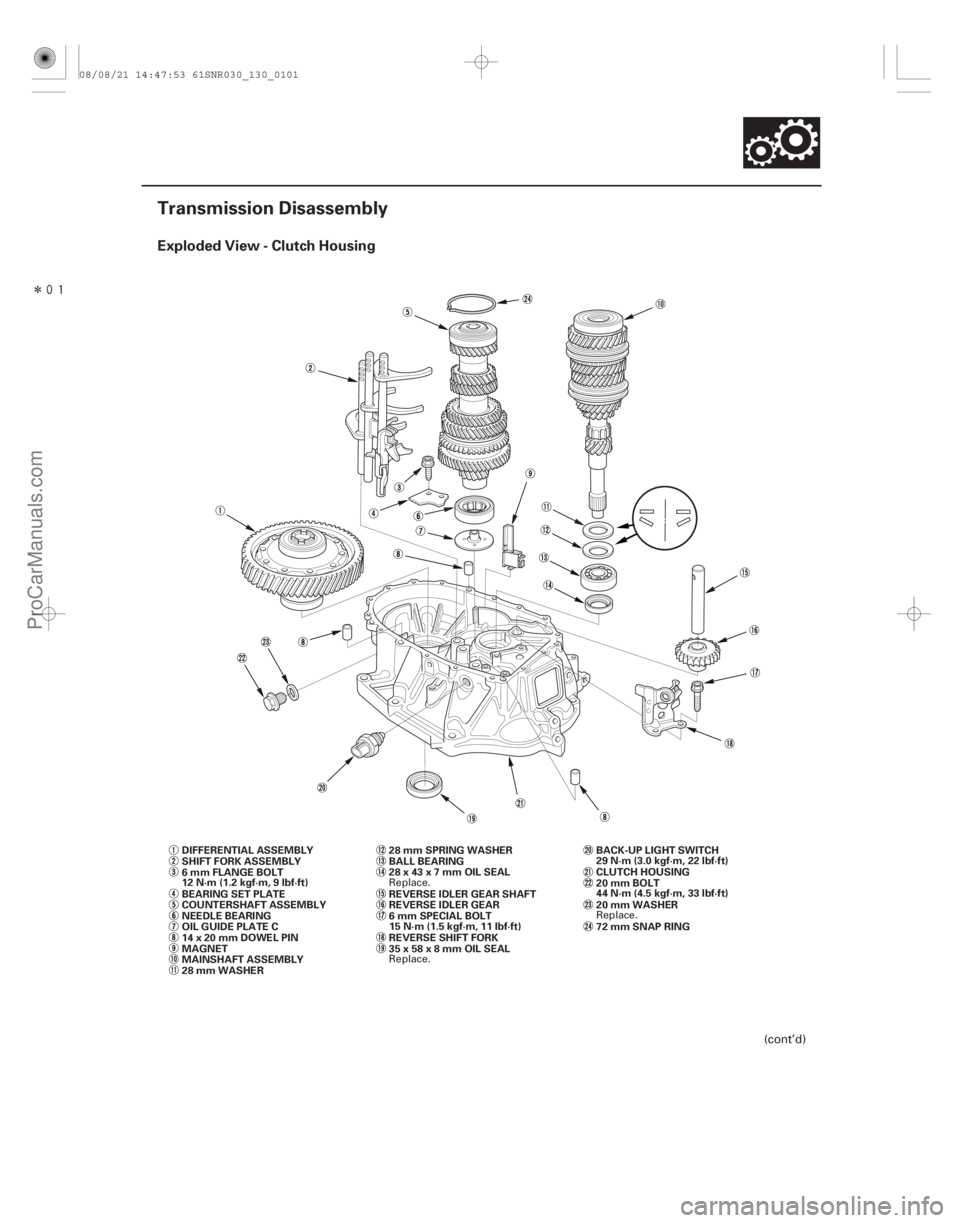
Exploded View - Clutch Housing
13-99
Transmission Disassembly
MAINSHAFT ASSEMBLY COUNTERSHAFT ASSEMBLY REVERSE IDLER GEAR BALL BEARING
REVERSE IDLER GEAR SHAFT
14x20mmDOWELPIN
MAGNET DIFFERENTIAL ASSEMBLY
OIL GUIDE PLATE C BEARING SET PLATE
NEEDLE BEARING
28 mm WASHER 28 mm SPRING WASHER
6 mm SPECIAL BOLT
REVERSE SHIFT FORK
SHIFT FORK ASSEMBLY
15 N·m (1.5 kgf·m, 11 lbf·ft)72 mm SNAP RING
6 mm FLANGE BOLT
12 N·m (1.2 kgf·m, 9 lbf·ft)
35x58x8mmOILSEAL 28x43x7mmOILSEAL 20 mm WASHER BACK-UP LIGHT SWITCH
29N·m(3.0kgf·m,22lbf·ft)
20 mm BOLT
44N·m(4.5kgf·m,33lbf·ft) CLUTCH HOUSING
(cont’d)
Replace. Replace.Replace.
08/08/21 14:47:53 61SNR030_130_0101
ProCarManuals.com
DYNOMITE -2009-
Page 869 of 2893

TRANSMISSION HOUSING
32 mm SEALING CAP
34 N·m (3.5 kgf·m, 25 lbf·ft)
10 mm SEALING WASHER")
�����
Exploded View - Transmission Housing
13-100Manual Transmission
Transmission Disassembly (cont’d)
TRANSMISSION HOUSING
32 mm SEALING CAP
34 N·m (3.5 kgf·m, 25 lbf·ft)
10 mm SEALING WASHER
FILLER PLUG
44 N·m (4.5 kgf·m, 33 lbf·ft)
40x56x8mmOILSEAL
10 mm FLANGE BOLT
44 N·m (4.5 kgf·m, 33 lbf·ft)
14 mm SEALING WASHER
TRANSMISSION HANGER A 8 mm FLANGE BOLT
27 N·m (2.8 kgf·m, 20 lbf·ft)
INTERLOCK BOLT
39 N·m (4.0 kgf·m, 29 lbf·ft)
OIL GUIDE PLATE M
72 mm SHIM
OIL GUTTER PLATE
DRAIN PLUG
39 N·m (4.0 kgf·m, 29 lbf·ft) 20 mm SEALING WASHER STEEL BALL SPRING
TRANSMISSION HANGER B DETENT BOLT
22 N·m (2.2 kgf·m, 16 lbf·ft)
12 mm SEALING WASHER
HARNESS BRACKET A
6 x 30 mm FLANGE BOLT
12 N·m (1.2 kgf·m, 9 lbf·ft) 8x14mmDOWELPIN
CHANGE LEVER ASSEMBLY TRANSMISSION HANGER
10 mm FLANGE BOLT
44 N·m (4.5 kgf·m, 33 lbf·ft)
6 x 20 mm FLANGE BOLT
12 N·m (1.2 kgf·m, 9 lbf·ft) 6 mm FLANGE BOLT
12 N·m (1.2 kgf·m, 9 lbf·ft) OUTPUT SHAFT (COUNTERSHAFT)
SPEED SENSOR
O-RING
80 mm SHIM Replace.
Replace.
Replace. Replace. Replace.Replace.
08/08/21 14:47:54 61SNR030_130_0102
ProCarManuals.com
DYNOMITE -2009-
Page 872 of 2893
�����
����������
13-103
D
E B
C
F A
A B M
B
A
12. Apply tape to the mainshaft splines to protect the seal, then remove the mainshaft assembly (A) and
the countershaft assembly (B) with the shift fork
assembly (C) from the clutch housing (D).
13. Remove the 28 mm spring washer (E) and the 28 mm washer (F).
14. Remove the differential assembly (A) and the magnet (B). 15. Remove the oil gutter plate (A), the 72 mm shim (B),
and oil guide plate M.
08/08/21 14:47:57 61SNR030_130_0105
ProCarManuals.com
DYNOMITE -2009-