Page 616 of 2893

GND (BLK)
ROCKER ARM OIL CONTROL SOLENOID
2P CONNECTOR
ROCKER ARM OIL CONTROL SOLENOID 2P CONNECTOR")
��������
�µ
�µ �µ
�µ
�µ
�µ
YES
NO
YES
NO
YES
NO
11-292VTEC/VTC
DTC Troubleshooting (cont’d)
GND (BLK)
ROCKER ARM OIL CONTROL SOLENOID
2P CONNECTOR
ROCKER ARM OIL CONTROL SOLENOID 2P CONNECTOR
ECM/PCM CONNECTOR B (44P)
VTS (GRN/YEL)
VTS (GRN/YEL)
8. Check for continuity between rocker arm oil control
solenoid 2P connector terminal No. 1 and body
ground.
Go to step 9.
Repair open in the wire between the rocker
arm oil control solenoid and G101; A/T model
(see page 22-16), M/T model (see page 22-18), then
go to step 13.
9. Jump the SCS line with the HDS.
10. Disconnect ECM/PCM connector B (44P). 11. Check for continuity between ECM/PCM connector
terminal B34 and rocker arm oil control solenoid 2P
connector terminal No. 2.
Go to step 19.
Repair open in the wire between the ECM/
PCM (B34) and the rocker arm oil control solenoid,
then go to step 13.
12. Replace the rocker arm oil control valve (see page 11-296).
13. Reconnect all connectors.
14. Turn the ignition switch to ON (II).
15. Reset the ECM/PCM with the HDS.
16. Do the ECM/PCM idle learn procedure (see page 11-310).
17. Check for Temporary DTCs or DTCs with the HDS.
Check for poor connections or loose
terminals at the rocker arm oil control solenoid and
theECM/PCM,thengotostep1.
Go to step 18.
Wire side of female terminals Wire side of female terminals
Terminal side of female terminals
Is there continuity? Is there continuity?
Is DTC P2649 indicated?
08/08/21 14:28:27 61SNR030_110_0292
ProCarManuals.com
DYNOMITE -2009-
Page 617 of 2893

�µ
�µ
�µ
�µ �µ
�µ
YES
NO
YES
NO YES
NO
11-293
18. Monitor the OBD STATUS for DTC P2649 in the
DTCs MENU with the HDS.
Troubleshooting is complete. If any other
Temporary DTCs or DTCs were indicated in step 17,
go to the indicated DTC’s troubleshooting.
If the screen indicates FAILED, check for poor
connections or loose terminals at the rocker arm oil
control solenoid and the ECM/PCM, then go to step
1. If the screen indicates NOT COMPLETED, keep
idling until a result comes on.
19. Reconnect all connectors.
20. Update the ECM/PCM if it does not have the latest software (see page 11-227), or substitute a known-
good ECM/PCM (see page 11-7).
21. Start the engine, and let it idle.
22. Check for Temporary DTCs or DTCs with the HDS.
Check for poor connections or loose
terminals at the rocker arm oil control solenoid and
the ECM/PCM. If the ECM/PCM was updated,
substitute a known-good ECM/PCM (see page 11-7),
then go to step 21. If the ECM/PCM was substituted,
go to step 1.
Go to step 23. 23. Monitor the OBD STATUS for DTC P2649 in the
DTCs MENU with the HDS.
If the ECM/PCM was updated,
troubleshooting is complete. If the ECM/PCM was
substituted, replace the original ECM/PCM
(see page 11-228). If any other Temporary DTCs or
DTCs were indicated in step 22, go to the indicated
DTC’s troubleshooting.
If the screen indicates FAILED, check for poor
connections or loose terminals at the rocker arm oil
control solenoid and the ECM/PCM. If the ECM/
PCM was updated, substitute a known-good ECM/
PCM(seepage11-7),thengotostep21.IftheECM/
PCM was substituted, go to step 1. If the screen
indicates NOT COMPLETED, keep idling until a
result comes on.
Does t he scr een i nd i cat e PASSE D?
Is DTC P2649 indicated? Does t he scr een i nd i cat e PASSE D?
08/08/21 14:28:27 61SNR030_110_0293
ProCarManuals.com
DYNOMITE -2009-
Page 618 of 2893
����
Closed
Open
11-294VTEC/VTC
VTC Oil Control Solenoid Valve Removal/Test/Installation
A
C
B
12 N·m
(1.2 kgf·m,
8.7 lbf·ft)
A VTC")
���
��������
���
�(�#�'�����������
���������������������������)����
Closed
Open
11-294VTEC/VTC
VTC Oil Control Solenoid Valve Removal/Test/Installation
A
C
B
12 N·m
(1.2 kgf·m,
8.7 lbf·ft)
A VTC OIL CONTROL SOLENOID VALVE 2P CONNECTOR
BATTERY
A
1.2 mm
(0.05 in.)
1. Disconnect the VTC oil control solenoid valve 2P
connector.
2. Remove the ground wire (A).
3. Remove the bolt (B) and the VTC oil control solenoid valve (C).
4. Check the VTC oil control solenoid valve strainer for clogging. If the strainer is clogged, replace the
VTC oil control solenoid valve.
5. Note the amount of valve opening by observing the position of the piston shoulder (A) through the
valve retard drain port. If you see the shoulder of
the piston, the valve is open and must be replaced. 6. Connect the battery positive terminal to VTC oil
control solenoid valve 2P connector terminal No. 2.
7. Connect the battery negative terminal to VTC oil control solenoid valve 2P connector terminal No. 1.
Appearance of inner valve (A) in the port should be
at least 1.2 mm (0.05 in.). If the inner valve does not
open, replace it; then go to step 8.
Terminal side of male terminals
08/08/21 14:28:28 61SNR030_110_0294
ProCarManuals.com
DYNOMITE -2009-
Page 619 of 2893
�������
�(�#�'�����������
�����������
�������
� �����)�
��
11-29511-295
CMP Sensor A Replacement
12 N·m
(1.2 kgf·m, 8.7 lbf·ft)
A
12 N·m
(1.2 kgf·m,
8.7 lbf·ft)
B
C
A
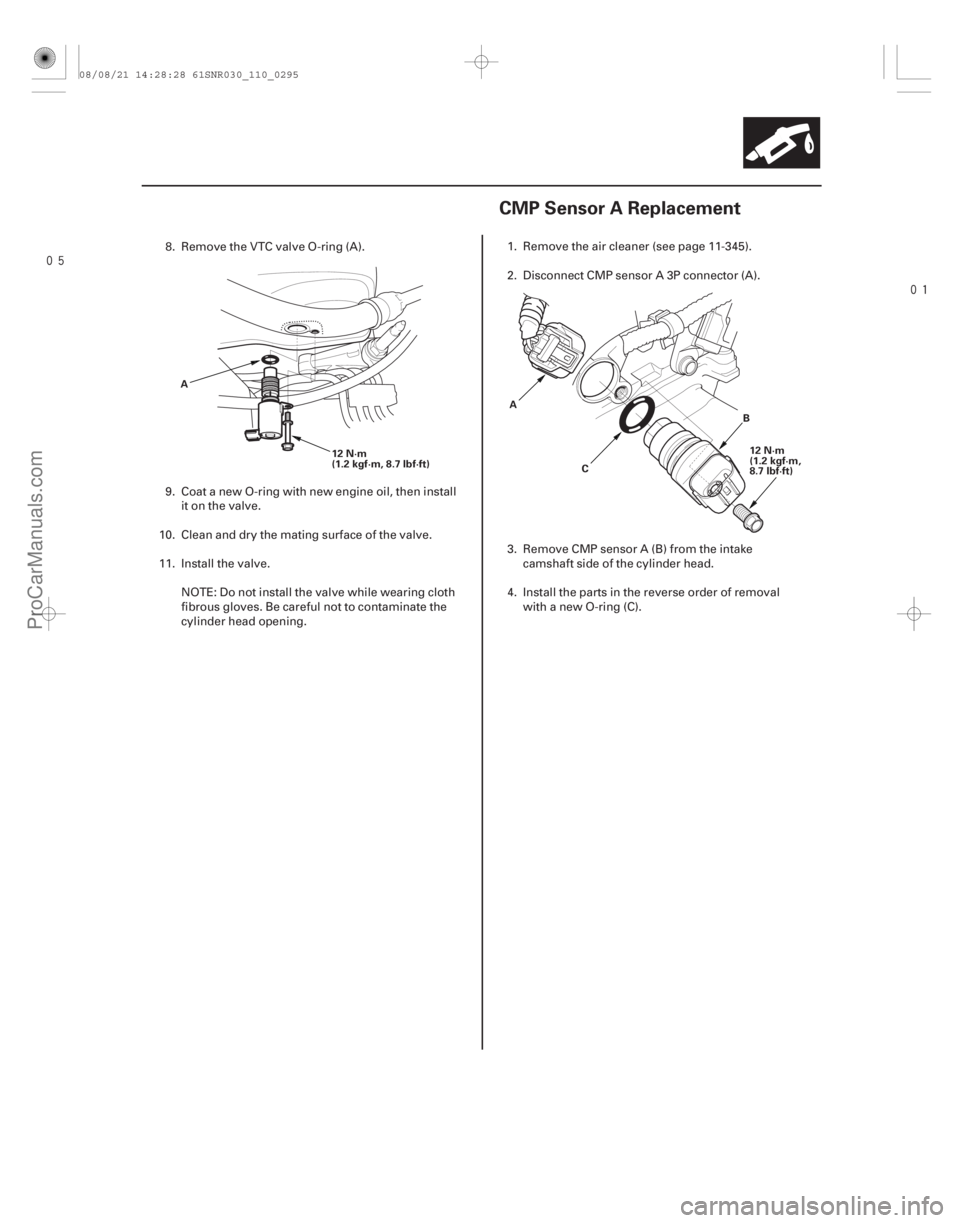
8. Remove the VTC valve O-ring (A).
9. Coat a new O-ring with new engine oil, then install
it on the valve.
10. Clean and dry the mating surface of the valve.
11. Install the valve. NOTE: Do not install the valve while wearing cloth
fibrous gloves. Be careful not to contaminate the
cylinder head opening. 1. Remove the air cleaner (see page 11-345).
2. Disconnect CMP sensor A 3P connector (A).
3. Remove CMP sensor A (B) from the intake
camshaft side of the cylinder head.
4. Install the parts in the reverse order of removal with a new O-ring (C).
08/08/21 14:28:28 61SNR030_110_0295
ProCarManuals.com
DYNOMITE -2009-
Page 620 of 2893
�������
�(�#�'�����������
�����������
�������
� �����)�
��
11-29511-295
CMP Sensor A Replacement
12 N·m
(1.2 kgf·m, 8.7 lbf·ft)
A
12 N·m
(1.2 kgf·m,
8.7 lbf·ft)
B
C
A
8. Remove the VTC valve O-ring (A).
9. Coat a new O-ring with new engine oil, then install
it on the valve.
10. Clean and dry the mating surface of the valve.
11. Install the valve. NOTE: Do not install the valve while wearing cloth
fibrous gloves. Be careful not to contaminate the
cylinder head opening. 1. Remove the air cleaner (see page 11-345).
2. Disconnect CMP sensor A 3P connector (A).
3. Remove CMP sensor A (B) from the intake
camshaft side of the cylinder head.
4. Install the parts in the reverse order of removal with a new O-ring (C).
08/08/21 14:28:28 61SNR030_110_0295
ProCarManuals.com
DYNOMITE -2009-
Page 621 of 2893
���
�(�#�'�����������
�������������
���
��� �����)���� ���
�(�#�'�����������
�������������
���
��� �����)����
11-29611-296 VTEC/VTC
Rocker Arm Oil Control Valve
Removal/Installation
Rocker Arm Oil Pressure Switch
Removal/Installation
DE
C
12 N·m
(1.2 kgf·m, 8.7 lbf·ft) A
B B
22 N·m
(2.2 kgf·m, 16 lbf·ft)
12 N·m
(1.2 kgf·m, 8.7 lbf·ft)
A
C
1. Remove the cowl cover and the under-cowl panel
(see page 20-163).
2. Disconnect the rocker arm oil control valve 2P connector (A) and the rocker arm oil pressure
switch 2P connector (B).
3. Remove the bolts (C).
4. Remove the rocker arm oil control valve (D).
5. Install the parts in the reverse order of removal with a new solenoid valve filter (E). 1. Remove the rocker arm oil control valve (see page
11-296).
2. Remove the cover (A).
3. Remove the rocker arm oil pressure switch (B).
4. Install the parts in the reverse order of removal with a new O-ring (C).
08/08/21 14:28:29 61SNR030_110_0296
ProCarManuals.com
DYNOMITE -2009-
Page 660 of 2893
����
����� �����
�����
Connection with new retainer Reconnection to existing retainer
Connection to new fuel line
11-332Fuel Supply System
Fuel Line/Quick-Connect Fitting Installation (cont’d)
A
B A
C A
B
C
Sanoh-made
Tokai-made A
B
C C
4. Align the quick-connect fittings with the line (A),
and align the retainer locking tabs (B) with the
connector grooves (C). Then press the quick-
connect fittings onto the line until both retainer tabs
lock with a clicking sound.
NOTE: If it is hard to connect, put a small amount of
new engine oil on the line end.
08/08/21 14:30:56 61SNR030_110_0332
ProCarManuals.com
DYNOMITE -2009-
Page 663 of 2893
���
����
Installation
11-335
A
B A
B
1. Temporarily attach a new base gasket (A) to the
fuel tank unit (B), then insert the fuel tank unit
partially into the fuel tank.
NOTE: Be careful not to damage the new base gasket.
Be careful not to bend the fuel gauge sending unit.
Do not coat the base gasket with oil. 2. Transfer the base gasket (A) from the fuel tank unit
to the fuel tank.
3. Align the marks (B) on the fuel tank and the fuel tank unit, then insert the fuel tank unit into the fuel
tank until it sits on the base gasket.
NOTE: To prevent a fuel leak, check the base gasket,
visually or by hand, to make sure it is not pinched.
(cont’d)
08/08/21 14:30:58 61SNR030_110_0335
ProCarManuals.com
DYNOMITE -2009-